Piled Raft Foundation
1.0 Introduction
This tutorial demonstrates some of the support systems available in RS3. This tutorial models a square shaped piled raft foundation.
All tutorial files installed with RS3 can be accessed by selecting File > Recent > Tutorials Folder from the RS3 main menu. The starting file can be found in Piled Raft Foundation - starting file.rs3v3. The finished product of this tutorial can be found in the Pile Raft Foundation.rs3v3.
2.0 Starting the Model
- Select File > Recent > Tutorials Folder from the RS3 main menu.
- Open the starting file Piled Raft Foundation - starting file.rs3v3.
- The model should have initial project settings already defined for the user.
- Select Analysis > Project Settings

- Check the following inputs:
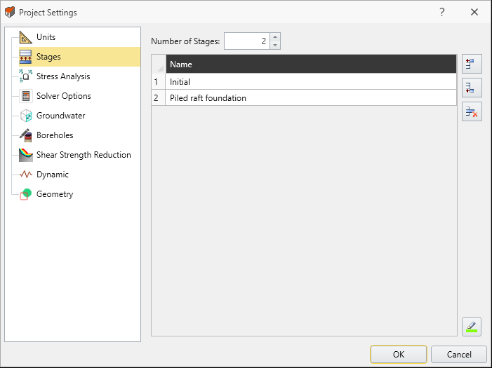
- In the Stages tab:
- Number of Stages = 2
- Stage 1 Name = Initial
- Stage 2 Name = Piled Raft Foundation
- Number of Stages = 2
- In the Groundwater tab:
- Method = Phreatic Surfaces
- Pore Fluid Unit Weight = 9.81 kN/m3
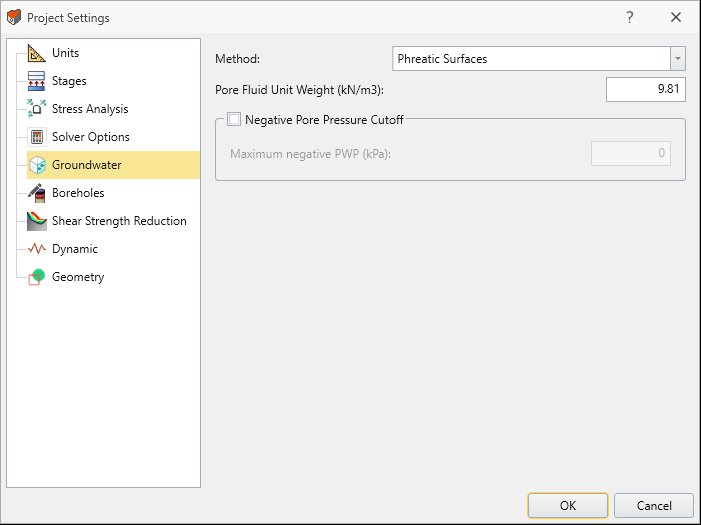
- Method = Phreatic Surfaces
- In the Stages tab:
- Click OK to close the dialog.
3.0 Defining the Materials
- Ensure the current workflow tab is set to Geology

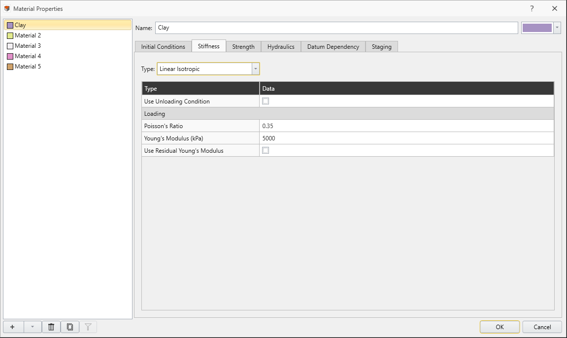
- Select Materials > Define Materials

- Check that you have the following inputs:
- In the Initial Conditions tab:
- Initial Element Loading = Field Stress & Body Force
- Unit Weight = 18 kN/m3
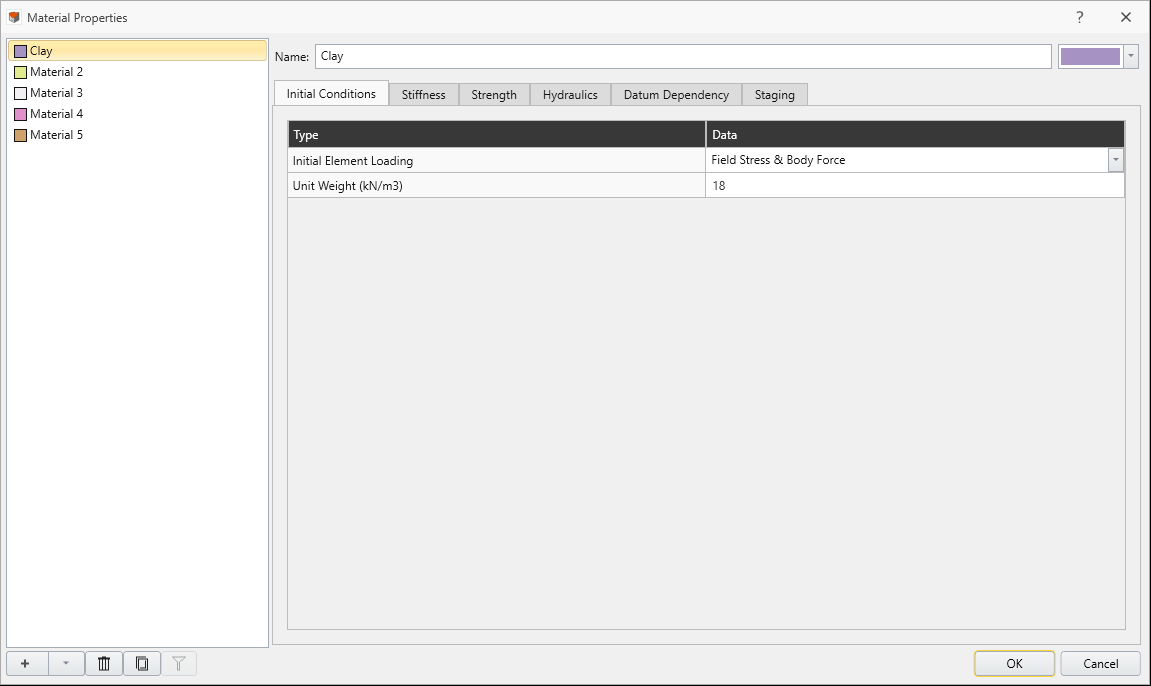
- Initial Element Loading = Field Stress & Body Force
- In the Strength tab:
- Material Type = Plastic
- Peak Cohesion = 4 kPa
- Peak Friction Angle = 30º
- Peak Tensile Strength = 0 kPa
- Residual Cohesion = 4 kPa
- Residual Friction Angle = 30º
- Residual Tensile Strength = 0 kPa
- Dilation Angle = 0º
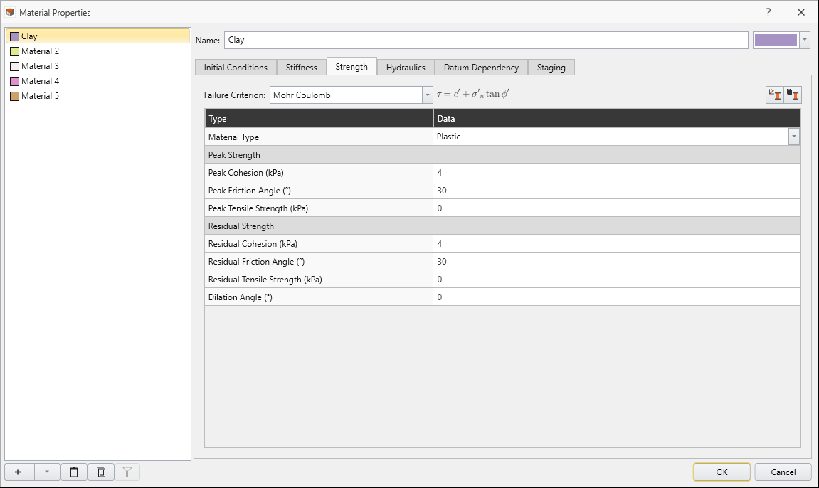
- Material Type = Plastic
- In the Stiffness tab:
- Type = Linear Isotropic
- Use Unloading Condition = No
- Poisson's Ratio = 0.35
- Young's Modulus = 5000 kPa
- Use Residual Young's Modulus = No
- Type = Linear Isotropic
- In the Initial Conditions tab:
- Click OK to close the dialog.
4.0 Creating Geometry
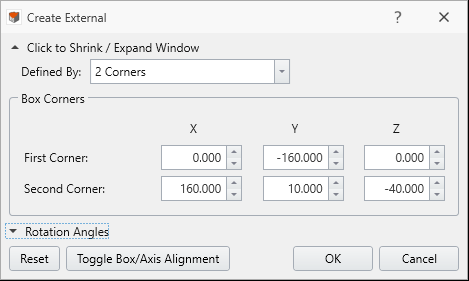
- Select Geometry > Create External Box.
- A Create External dialog will open. Enter the following:
- First Corner (x, y, z) = (0, -160, 0)
- Second Corner (x, y, z) = (160, 10, -40)
- First Corner (x, y, z) = (0, -160, 0)
- Click OK.
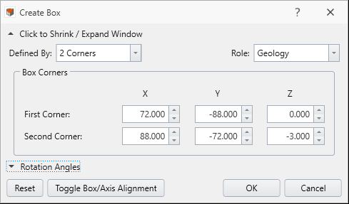
- Select Geometry > 3D Primitive Geometry > Box.
- Enter the following:
- Defined By = 2 Corners
- Role = Geology
- First Corner (x, y, z) = (72, -88, 0)
- Second Corner (x, y, z) = (88, -72, -3)
- Defined By = 2 Corners
- Click OK.
- Select Geometry > 3D Boolean > Divide All Geometry

- We will be using all default values.
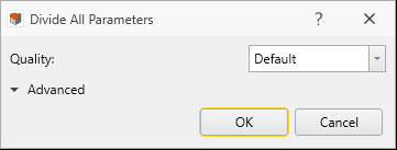
- Click OK.
5.0 Adding Supports
5.1 Adding Liners
- Select the Support workflow tab
 at the top of the screen.
- Before adding the liner, we must select the faces that we want the liner to be assigned to.
- Select Edit > Selection Mode > Faces Selection

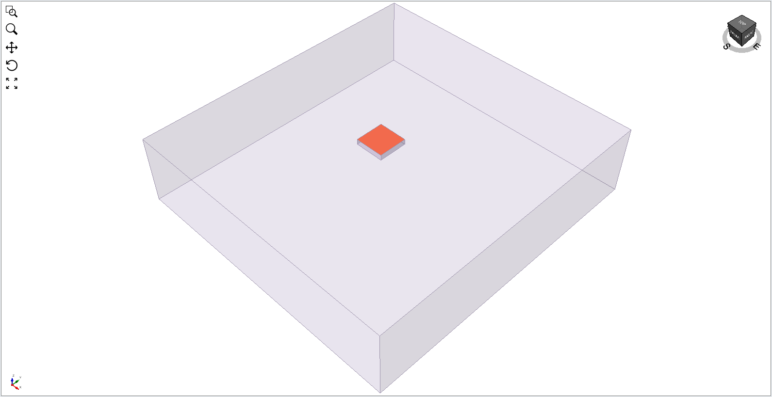
- Select the top face of the smaller box either using the XY-plane modeler view or the 3D modeler view. When selected the 3D modeler view should look similar to the following:

- Select Support > Liners > Add Lining

- Press the pencil icon
 beside Lining 1 to open the Liner Composition dialog.
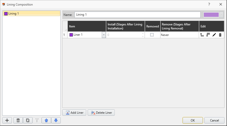
- Navigate to the last column (Edit) and select the pencil icon to open the Liner Properties dialog.
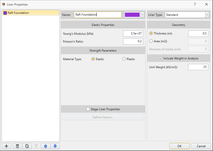
- Enter the following values and leave all else default:
- Click OK to save and exit the liner properties dialog, then click OK to exit the lining composition dialog.
- In the Add Lining dialog, set Install at stage = Piled raft foundation.
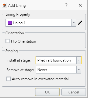
- Click OK.
| Name | Young's Modulus (kPa) | Poisson's ratio | Thickness (m) | Include Weight in Analysis | Unit Weight (kN/m3) | |
|---|---|---|---|---|---|---|
| Liner 1 | Raft Foundation | 35000000 | 0.2 | 0.5 | Active | 25 |
5.2 Adding Piles
In RS3, a pile is simulated as a beam. Therefore, beam properties are used when defining pile properties, such as Young's Modulus, Poisson's ratio and the pile dimensions. Material properties distinct for a pile, such as the soil-pile interaction, are found in the Pile Properties dialog.
- Select Support > Beams > Define Beams.
- Enter the following values for the beam parameters:
- Leave all other values as default.
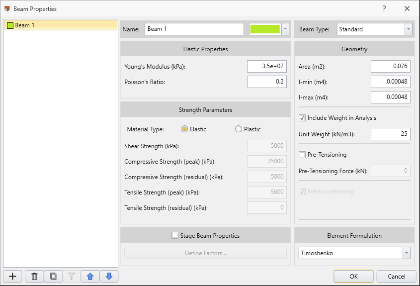
- Click OK to save and close the Beam Properties dialog.
- Select Edit > Selection Mode > Face Selection
- Select the top face of the foundation.
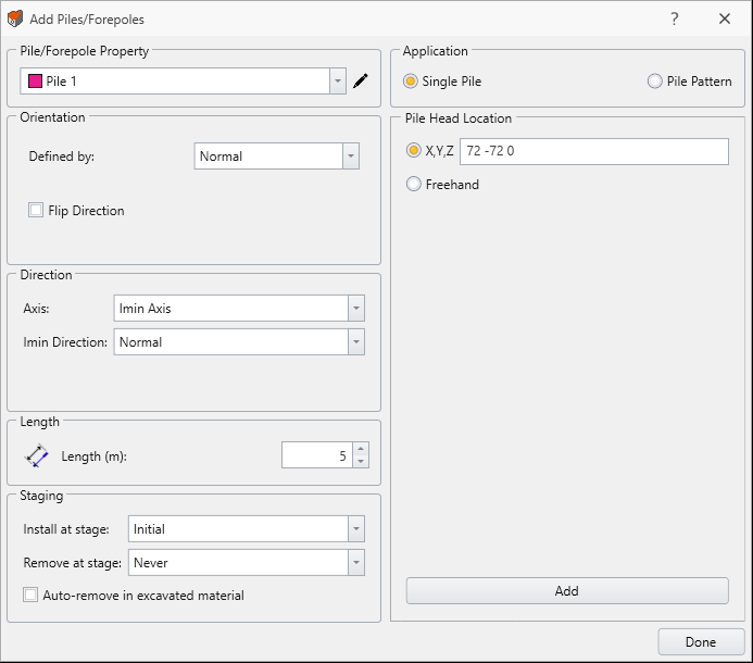
- Select Support > Piles or Forepoles > Add Piles or Forepoles

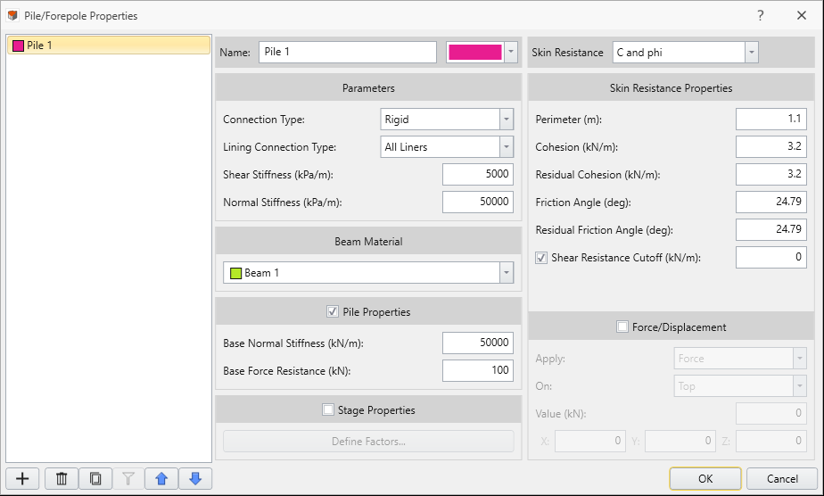
- Select the pencil icon located next to Pile 1 to open the Pile/Forepole Properties dialog.
- Enter the following parameter inputs:
- Set Connection Type = Rigid
- Lining Connection Type = All Liners
- Shear Stiffness = 5000 kPa/m
- Normal Stiffness = 50000 kPa/m
- Base Normal Stiffness = 50000 kN/m
- Base Force Resistance = 100 kN
- Skin Resistance = C and phi
- Perimeter = 1.1m
- Cohesion = 3.2 kN/m
- Residual Cohesion = 3.2 kN/m
- Friction Angle = 24.79º
- Residual Friction Angle = 24.79°
- Set Connection Type = Rigid
- Leave all other values as default. Click OK.
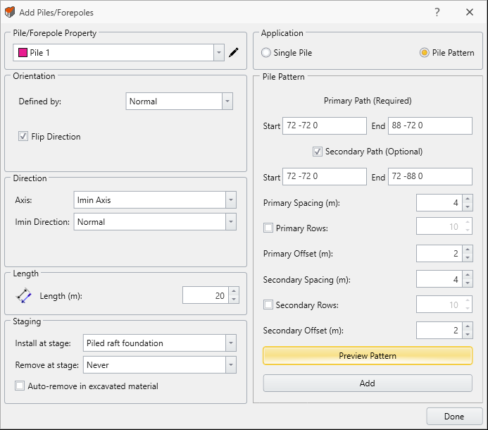
- Now that we've returned to the Add Piles/Forepoles dialog, enter the following:
- Flip Direction = Active
- Length = 20m
- Install at stage = Piled Raft Foundation
- Application = Pile Pattern
- Primary Spacing = 4
- Secondary Spacing = 4
- Primary Offset = 2
- Secondary Offset = 2
- Flip Direction = Active
- Make sure the Secondary Path (Optional) is enabled.
- We need to define the Start and End points of our pile pattern paths.
- In the XY plane viewport select the top-left vertex of the selected face, followed by the top-right vertex. At this point we have defined the Primary Path. Subsequently, we can set the Secondary Path by selecting the top-left vertex again, followed by the bottom-left vertex.
- You will see the coordinates are now being displayed for the Primary Path and Secondary Path.
- Alternatively, we could have entered the coordinates manually instead of using the vertices selection tool.
- Select Preview Pattern to ensure everything was entered correctly. The model should look like the following.
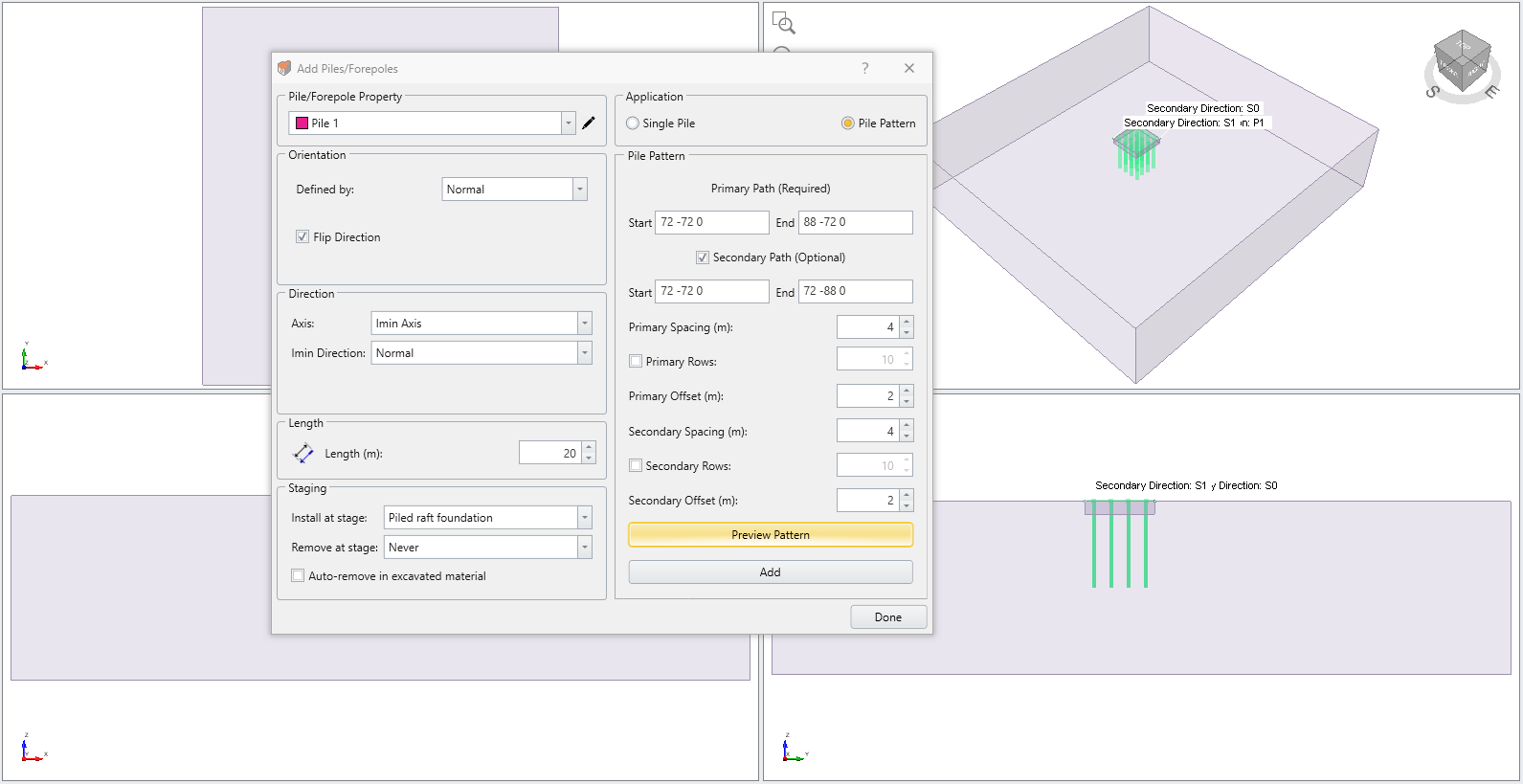
- Select Add to add the piles to the model. Click Done to close the dialog.
| Name | Young's Modulus (kPa) | Poisson's ratio | Area (m2) | I-min (m4) | I-max (m4) | Include Weight in Analysis | Unit Weight (kN/m3) | |
|---|---|---|---|---|---|---|---|---|
| Beam 1 | Beam 1 | 35000000 | 0.2 | 0.076 | 0.00048 | 0.00048 | Active | 25 |
You must keep the Add Piles/Forepoles dialog open while you use any selection tools to define the Start and End points of a path.
The order of vertices selected does not matter in this tutorial as the foundation is square. You can choose any vertices to start, but the following sequence should be the same.
If you do not see the piles after selecting Done, it could be because the modeler is not on Piled Raft Foundation stage. Make sure to switch to Piled Raft Foundation Stage (Stage can be switched below viewport).
6.0 Groundwater Conditions
- Select the Groundwater workflow tab
 at the top of the screen.
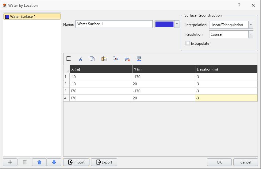
 - Select Groundwater > Add Water by Location

- In the Water by Location dialog, enter the four points (X, Y, Elevation):
- (-10, -170, -3)
- (170, -170, -3)
- (170, 20, -3)
- (-10, 20, -3)
- (-10, -170, -3)
- Click OK.
- Select Materials > Define Materials
- Navigate to the Clay's Hydraulics tab and change the Default Water Condition = Water Surface 1 and leave all other settings as default.
- Click OK. The red "X" symbol should now be gone, indicating that the water condition has been defined.
In the visibility pane you will notice that Water Surface 1 has a red "X" symbol. This is because the water condition in the material is undefined.
7.0 Adding Stress Loading
7.1 Adding Field Stress
- Select the Loads workflow tab

- Select Loading > Field Stress

- Make sure that the Field Stress Type is set to Gravity.
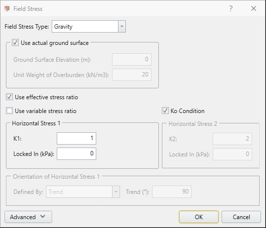
- Click OK to close.
7.2 Loading the Raft Foundation
Now we will place a surface load on the top face of the foundation.
- Select the face where the liner is installed on.
- Select Loading > Add Loads to Selected
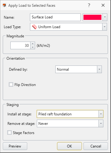
- Enter the following:
- Load Type = Uniform Load
- Magnitude = 30 kN/m2
- Install at stage = Piled raft foundation
- Load Type = Uniform Load
- All other settings should be left as default. Click OK to save and close the dialog.
8.0 Setting Boundary Conditions
- Select the Restraints workflow tab

- Select Restraints > Auto Restrain (Surface).
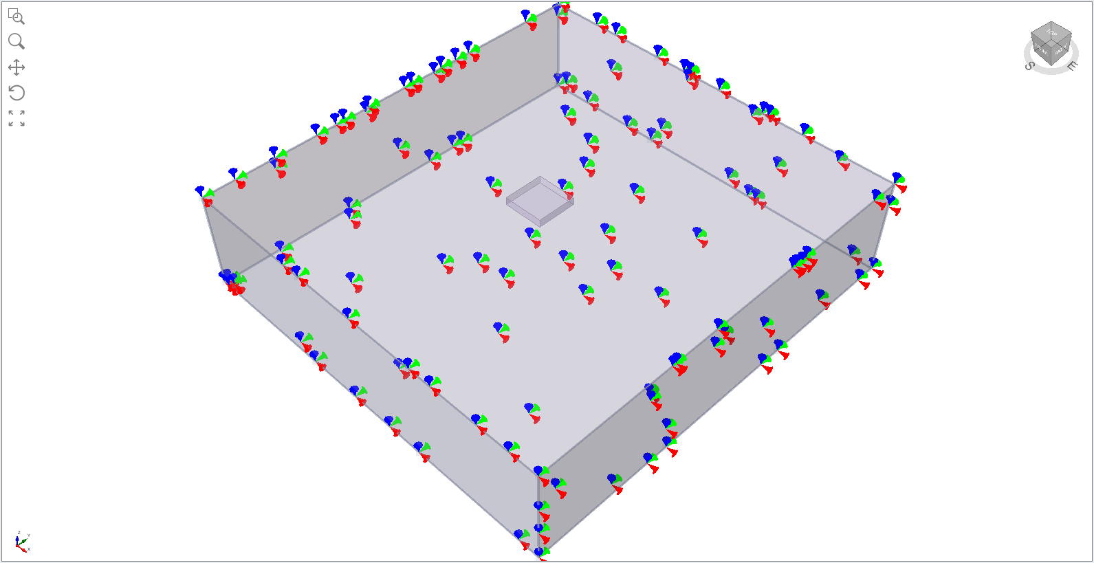
RS3 has a built-in "Auto Restrain" tool for use on underground models.
This completes the construction of the model's geometry.
9.0 Meshing
- Next, we move to the Mesh workflow tab

- Select Mesh > Mesh Settings

- Keep the Element type and Mesh Gradation 4-Noded Tetrahedra and Graded, respectively.
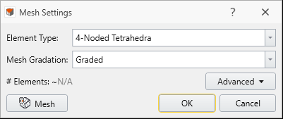
- Select Mesh
 . Then click OK. You should see the following:
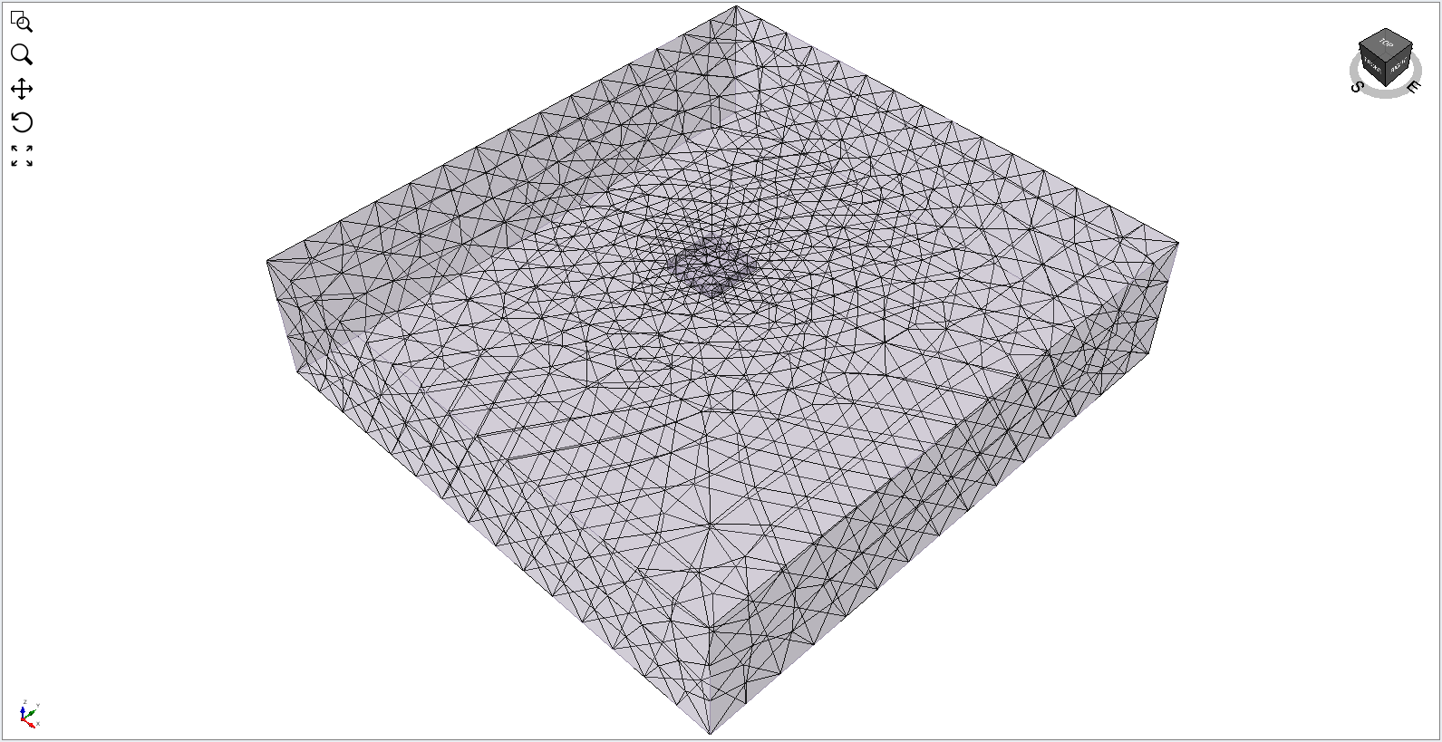
10.0 Computing Results
- Select the Compute workflow tab
 . You are now ready to compute the results.
 - Select Compute > Compute

11.0 Interpreting Results
- Select the Results workflow tab

- By default, the Element is set to Solids and Data Type = Sigma 1 Effective.
- To turn on the exterior contour, select Interpret > Show Exterior Contour.
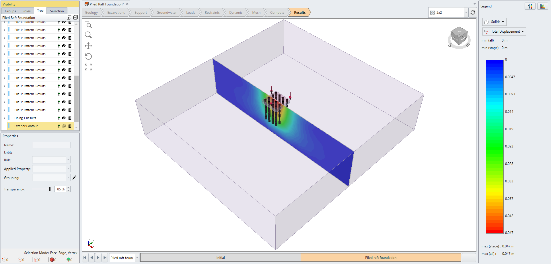
- To add a contour plane at the center of the model, select Interpret > Show Data on Plane > XZ Plane

- Under Plane Definition, set the Origin (x, y, z) = (80, -80, -20) and leave the plane orientation normal vector as default.
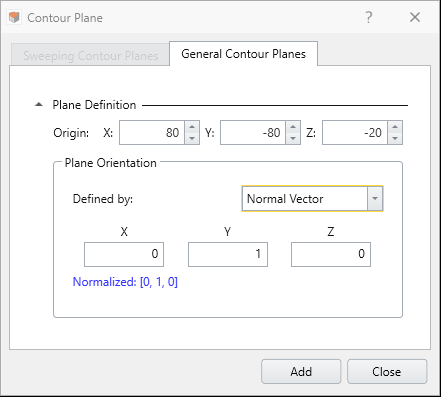
- Select Add and then Close.
- In the Legend bar on the right, change Data Type = Total Displacement.
- Next, we will change Element = Liners and Data Type = Moment Y.
- The internal moment (about the Y direction) of the liner is shown below:
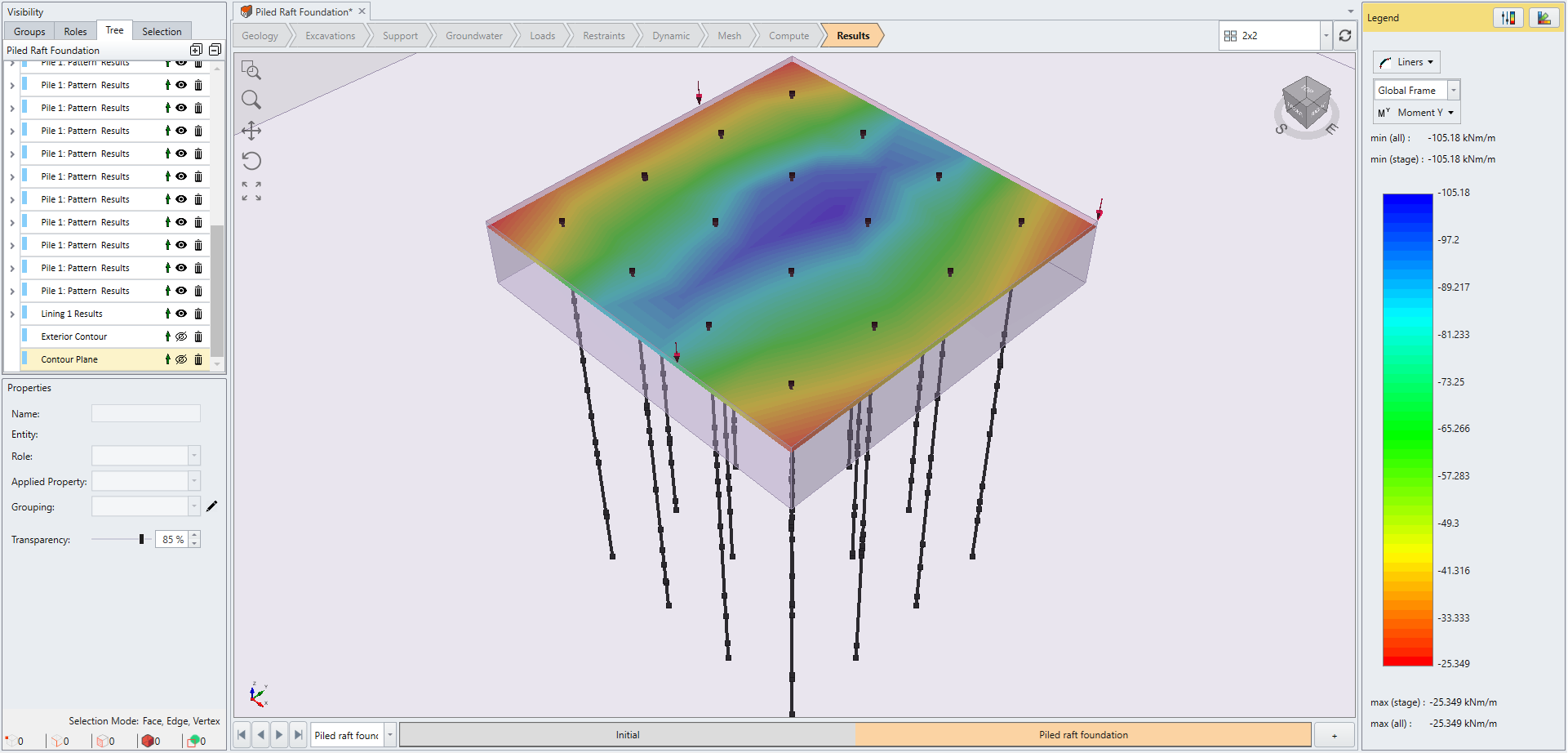
- The internal moment (about the Y direction) of the liner is shown below:
- Lastly, we will change Element = Beams & Piles and change the Data Type = Axial Force
To see the contour on the XZ Plane, click the "eye" icon next to Exterior Contour in the visibility pane to turn off the 3D Contour.
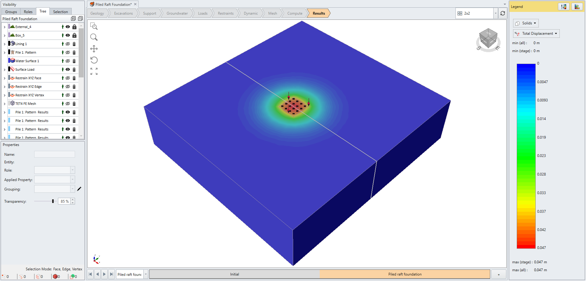
- The highest displacement, as expected, is in the center of the loaded foundation.
The axial force in the piles (at Stage 2) is shown below:
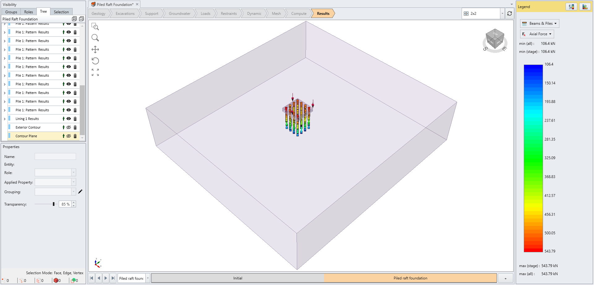
The axial force, as expected, decreases with depth.
This concludes the tutorial.