5 - RocFall2 Section Creator
This tutorial demonstrates the creation of 2D cross-sections for export to RocFall2, including batch section creation and export.
Topics Covered in this Tutorial:
- Multi-section export to RocFall2
- Group plots in RocFall2
- Runout distance reference line export to RocFall2
Finished Product:
The finished product of this tutorial can be found in the Tutorial 05 Terrain Generator data file. All tutorial files installed with RocFall3 can be accessed by selecting File > Recent Folders > Tutorials Folder from the RocFall3 main menu.
1.0 Open RocFall3 Model
Start RocFall3 by selecting Programs > Rocscience from the Windows Start menu. RocFall3 automatically opens a new blank document, which allows immediate model creation. If the RocFall3 application window is not already maximized, maximize it now so the full-screen space is available for use.
- Select the File > Recent > Tutorial Folder > Tutorial 05 initial.
- Go to the Tutorials folder included with the RocFall3 install. The default location of this folder is C:\Users\Public\Documents\Rocscience\RocFall3 Examples\Tutorials. Select the Tutorial 05 Initial file and click Open.
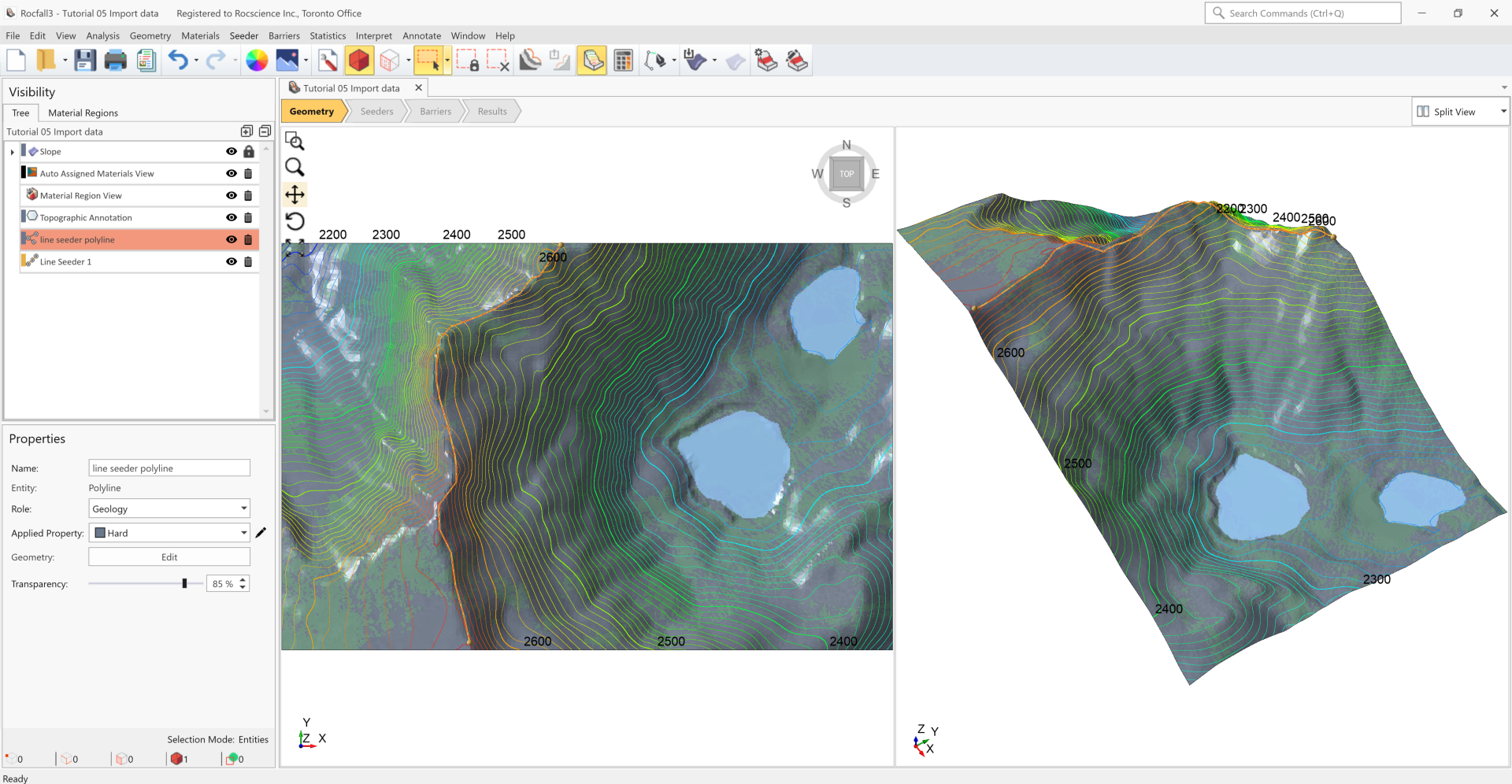
This model geometry was created from the import of a digital elevation model from satellite data via the Import Terrain feature. The Hard and Soft material regions were defined using the Image Segmentation feature, and the water body regions were manually drawn. The line seeder properties and location were also set. For more information on the process described above, visit Tutorial 2 Terrain Generator.
2.0 Reference Line for Runout Distance Calculation
- Select Geometry > Draw Polyline

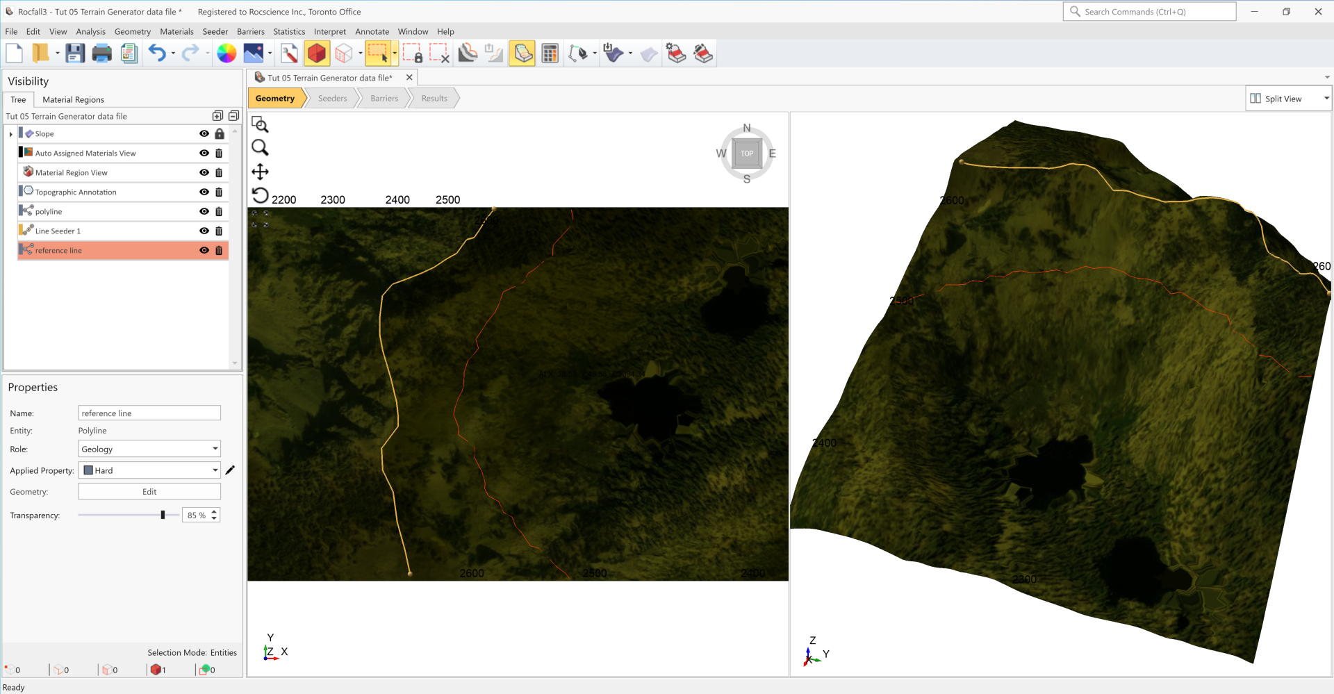
- Draw a line along the 2500 m elevation line, on the eastern slope, ensuring that it fully spans the model.
For exact polyline coordinates adopted for this model, open the provided Tutorial 05 Reference polyline.txt file in the Tutorials folder. Alternatively, the .txt file can be saved by right clicking here and selecting Save Link As. Select Import in the Draw Polyline dialog and import the points.
- Right-click and select Done.
- Name the polyline "Reference line".
3.0 Compute
- Click on the Compute
 icon in the toolbar (or select Analysis > Compute in the menu).
4.0 Results
- Navigate to the Results workflow tab.
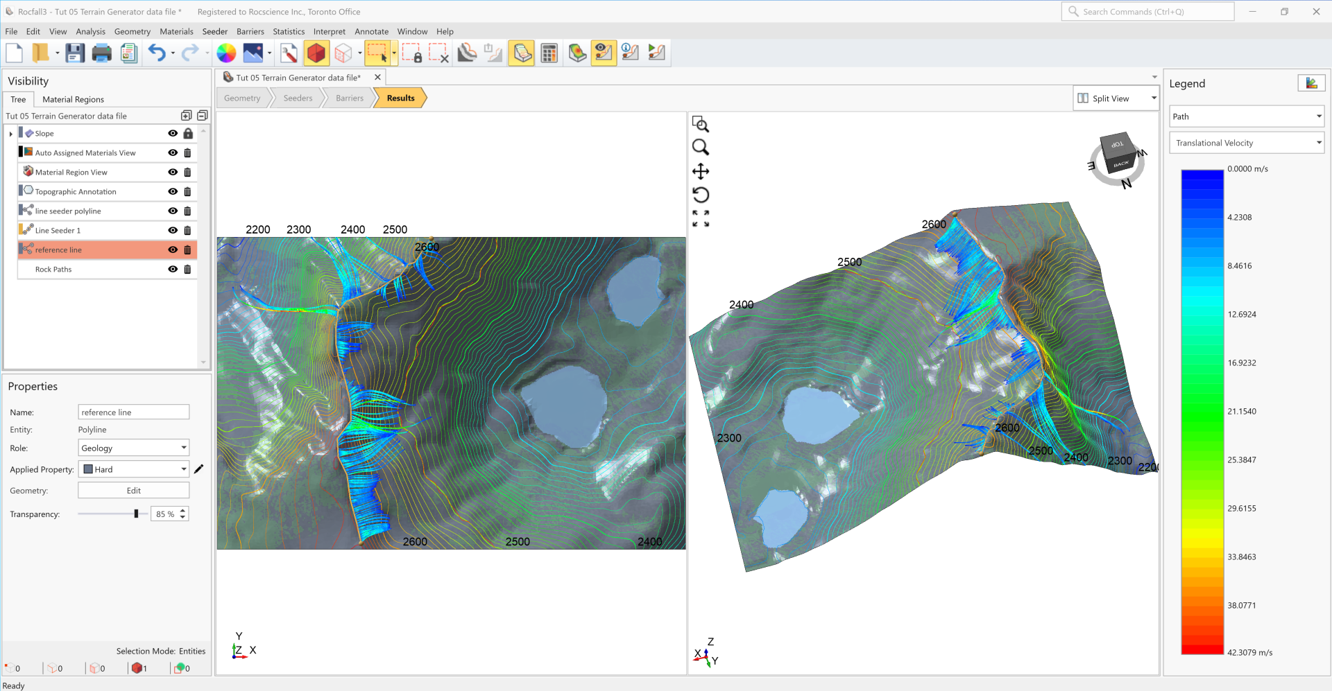
Contours of translational velocity are shown for the rock paths by default. The legend bar on the right can be used to select the result data type.
5.0 RocFall2 Multi-Section Creation and Export
RocFall3 supports batch section creation and export to RocFall2.
5.1 Creating Multiple Sections
- Select the Geometry workflow tab.
- From the menu, select Geometry > RocFall2 Section Creator

- In the Create/Edit Sections dialog, click Create Multiple Sections.

- For the Creation Method, select the Sections per Segment option.
- For Number of Sections enter 1. This means 1 cross-section will be created perpendicular to each segment of the drawn polyline (discussed next).
- Click Draw, and then left-click to draw a line similar to the Reference line as shown in the image below in magenta.
- When done drawing, right-click and select Done to exit drawing mode. Notice that 6 sections are created.
- Select OK to close the dialog.
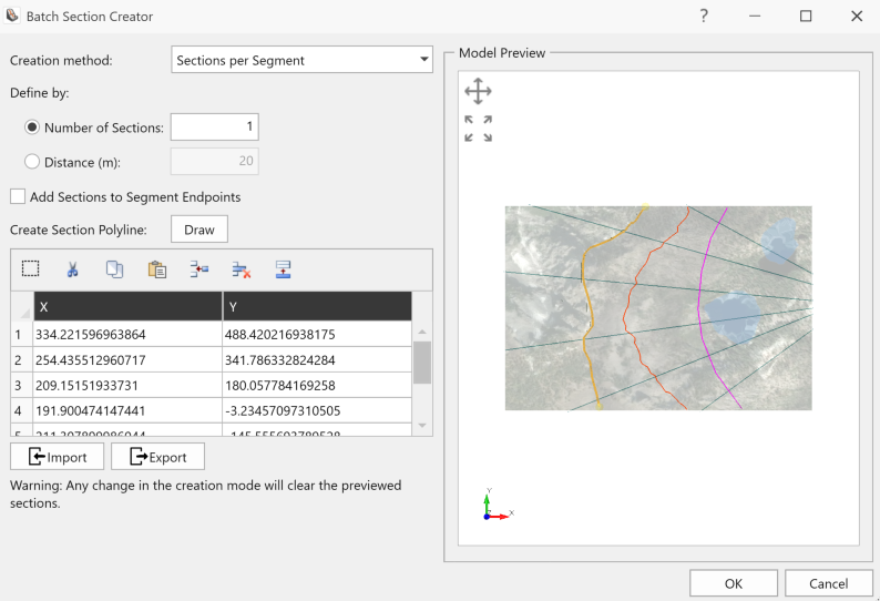
An alternative to drawing the polyline is to import its exact coordinates. Open the provided Tutorial 05 Creating Sections.txt file in the Tutorials folder. This .txt file is also available by right-clicking here and selecting Save Link As. Select Import in the Batch Section Creator dialog and import the points.
5.1.1 Deleting Sections
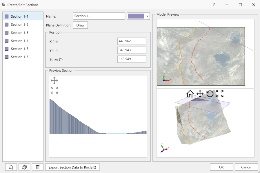
For this tutorial, delete the sections that don't intersect the reference line and line seeder.
- To delete a section, select the section from the list on the left of the Create/Edit Sections dialog and then select the Delete Icon
 located on the bottom-left of the dialog. Section 1-1 and Section 1-6 do not intersect the reference line or the line seeder, so delete these two sections.
 - Do not close the dialog just yet as more cross-sections are added in the next tutorial section.
5.1.2 Adding a Single Section
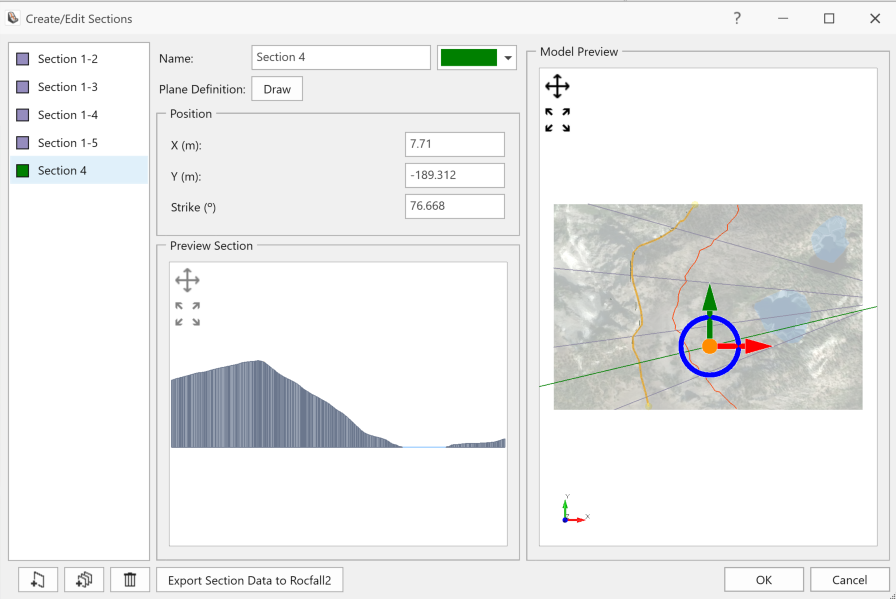
- To add a single section, click Add a Single Section
 located in the bottom-left corner of the dialog.
 - Click Draw, then select 2 arbitrary vertices that define the cross-section on the model preview. The following image shows the drawn section in green.
- Click OK to save and close the dialog.
5.2 Exporting Multiple Sections to RocFall2
- Go to the Geometry workflow tab.
- Select Analysis > Export All Sections to RocFall2 or click on Export All Sections to RocFall2
 icon in the toolbar.
 - Options in this dialog can be used to control the model information to be exported to RocFall2.
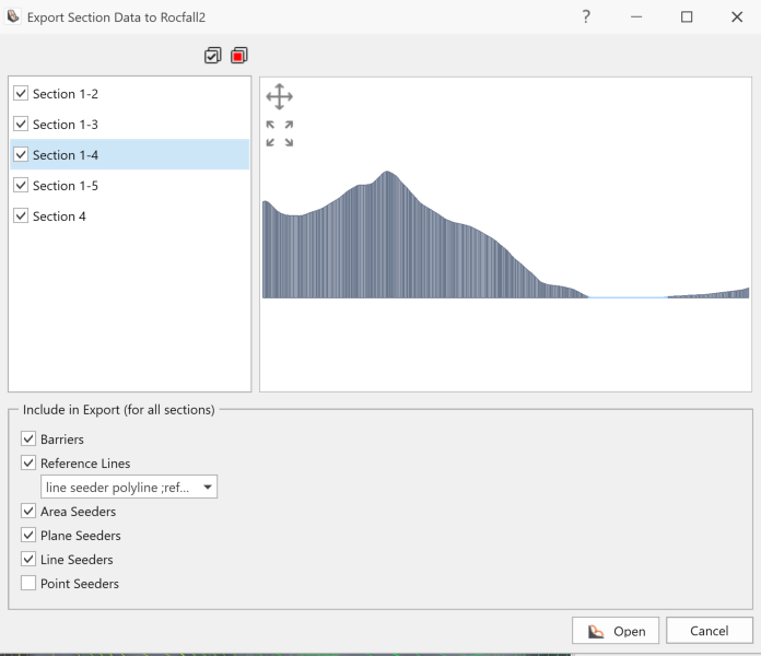
- Select all cross-sections.
- Ensure that the polyline defined as "Reference line" is selected from the Reference Lines drop down.
- Click Open
 to load RocFall2.
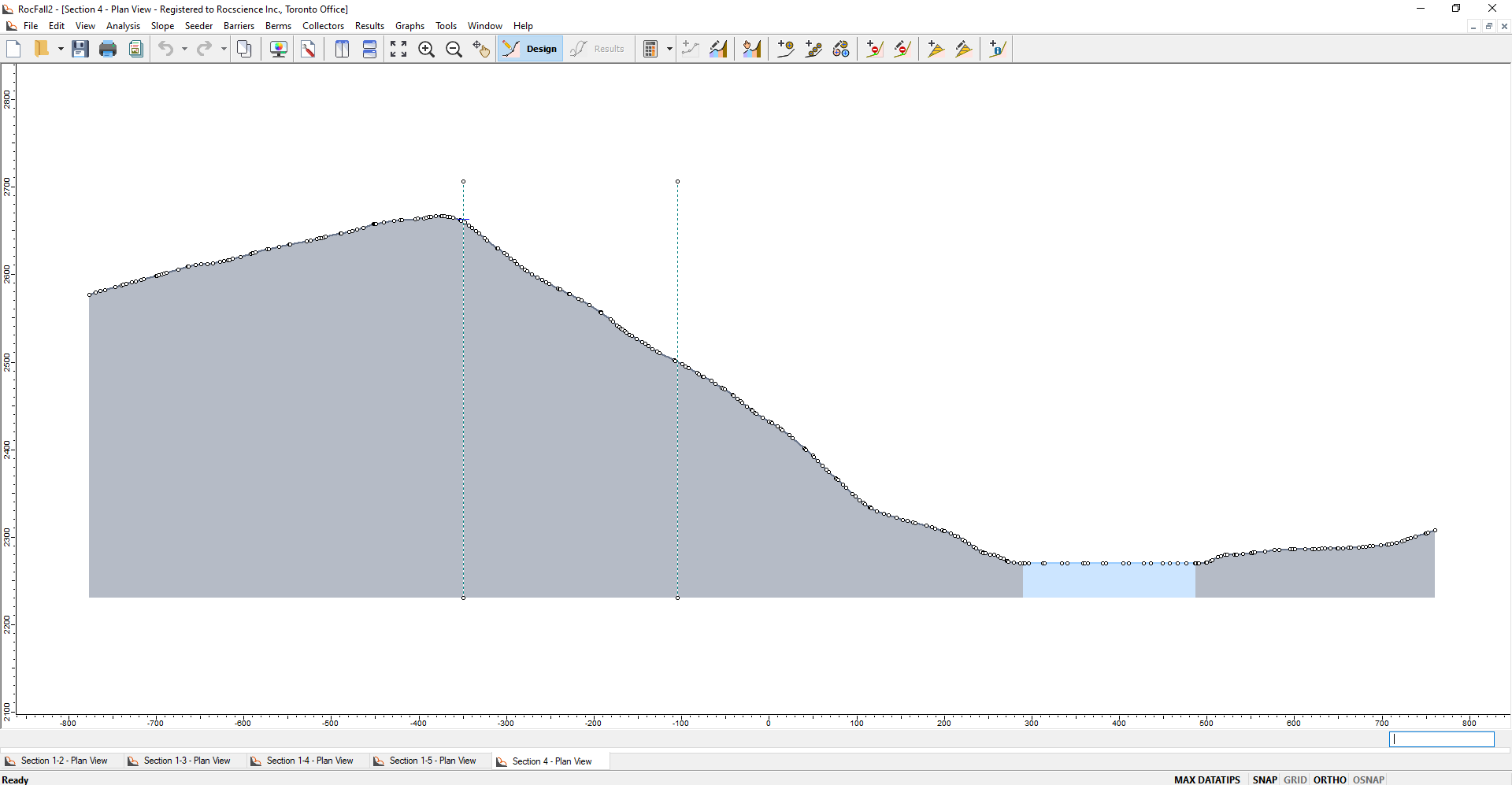
Once RocFall2 is open, all exported sections can be viewed.
The line seeder in RocFall3 is now a point seeder in RocFall2, displayed by a blue cross-hair. Any reference line from RocFall3 is displayed in RocFall2 as a dashed green line.
6.0 Compute RocFall2 Model
Given multiple RocFall2 sections were exported from RocFall3 using the batch export function, they can be computed using Batch Compute  , accessed from the drop-down arrow located next to the Compute icon in the toolbar.
7.0 Group Analysis
A Group Plot displays results from multiple sections in the same plot. This is a powerful tool that can be used to compare rockfall trajectories among multiple cross-sections.
- In RocFall2, select the Results tab.
- From the menu, select Graphs > Group Plots > Graph Endpoints.
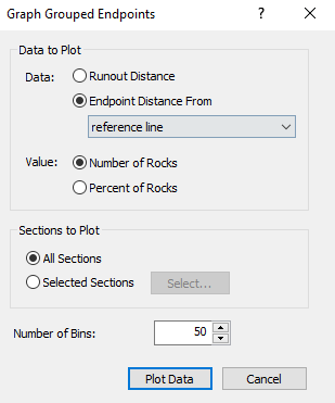
- Runout distances can be calculated with respect to a reference line. Select the Endpoint Distance From option in data settings, and select the polyline "Reference line".
- Click Plot Data.
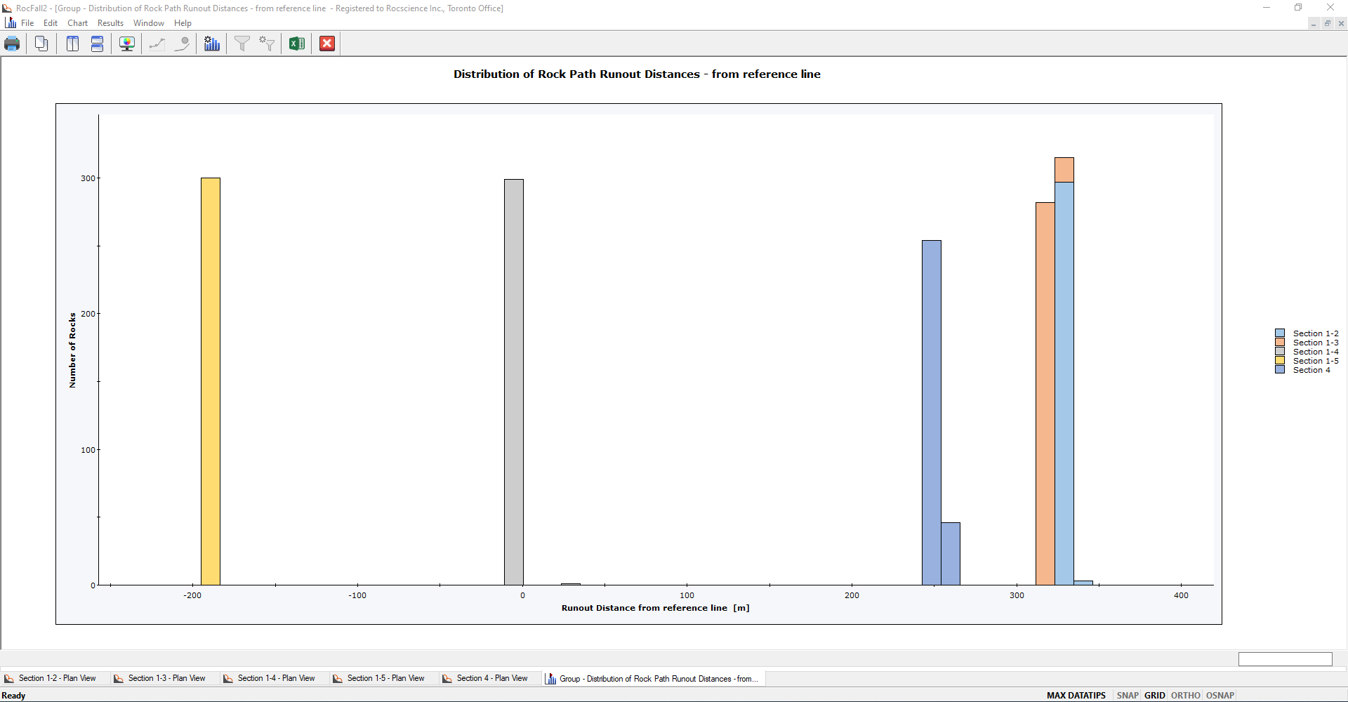
This group plot shows the runout distribution in each slope section with respect to the same reference line. The result for each section is shown in a distinct colour (legend on the right). Notice that some of the runout distances are negative, mainly from Section 1-5. The negative values indicate that the rock paths stopped before reaching the reference line.