Point Loads
Point Loads (e.g. a structural load on the upper surface of a slope, or the force applied by a waste rock berm to the toe of a slope) can be applied to a block with the Define Point Loads dialog. When adding a point load to a Toppling Model, the location of the load is required, and RocSlope2 enables point loads to be defined anywhere along the slope face or upper slope, at any angle, on the exposed upper edges of the toppling blocks.
To include Point Loads in the analysis:
- Select Loading > Define Loads > Point

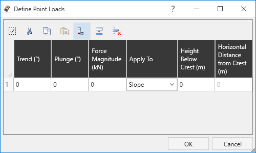
- The Define Point Loads dialog will open. Select the Add Single Row button
 to add a Point Load.
- Enter the Trend, Plunge, Force Magnitude, and Application.
- Based on the Application selected, enter a value for Height Below Crest (apply to Slope) or Horizontal Distance from Crest (apply to Upper Slope). This determines the location of the Point Load on the selected slope, and is only applicable for Toppling models.
- To add multiple Point Loads, select the Append Multiple Rows button indicate the number of rows to add, and select OK.
- Repeat step 3 for each load.
- Select OK to apply the loads.
Point Load Location
Point Loads can be applied on the slope face or upper slope of a RocSlope2 model. When you add a Point Load, the installation location is specified as follows for Toppling models:
- Slope Face - The location of the load is specified as the vertical height from the toe of the slope, which is determined by the value of Height Below Crest.
- Upper Slope - The location of the load is specified as the horizontal distance from the crest of the slope (even if the upper slope surface is not horizontal), which is determined by the value of Horizontal Distance from Crest.
When a load is added, RocSlope2 automatically determines the exact location of the load on the Toppling block surface corresponding to the number you have entered for Height Below Crest or Horizontal Distance from Crest. If the load does not appear where you intended, you can edit or delete the load and modify your input accordingly.
Point Load Implementation
In the RocSlope2 analysis, Point Loads can be added in the form of active loads which behave in a similar fashion to the addition of active Spot Bolts. This means that an Point Load with the same orientation as a Spot Bolt, and with a Magnitude equal to the capacity of the Spot Bolt, will have exactly the same effect on the Safety Factor, if the bolt model is active. See the Bolt Implementation topic for more information.
Point Load Statistics
If you are carrying out a Probabilistic Analysis, the Force Magnitude can be defined as a random variable. See the Point Load Statistics topic for more information.
Display of Point Loads
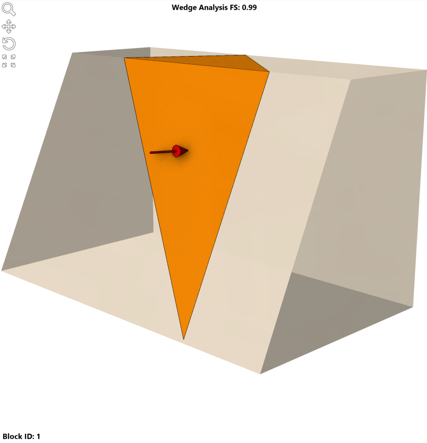
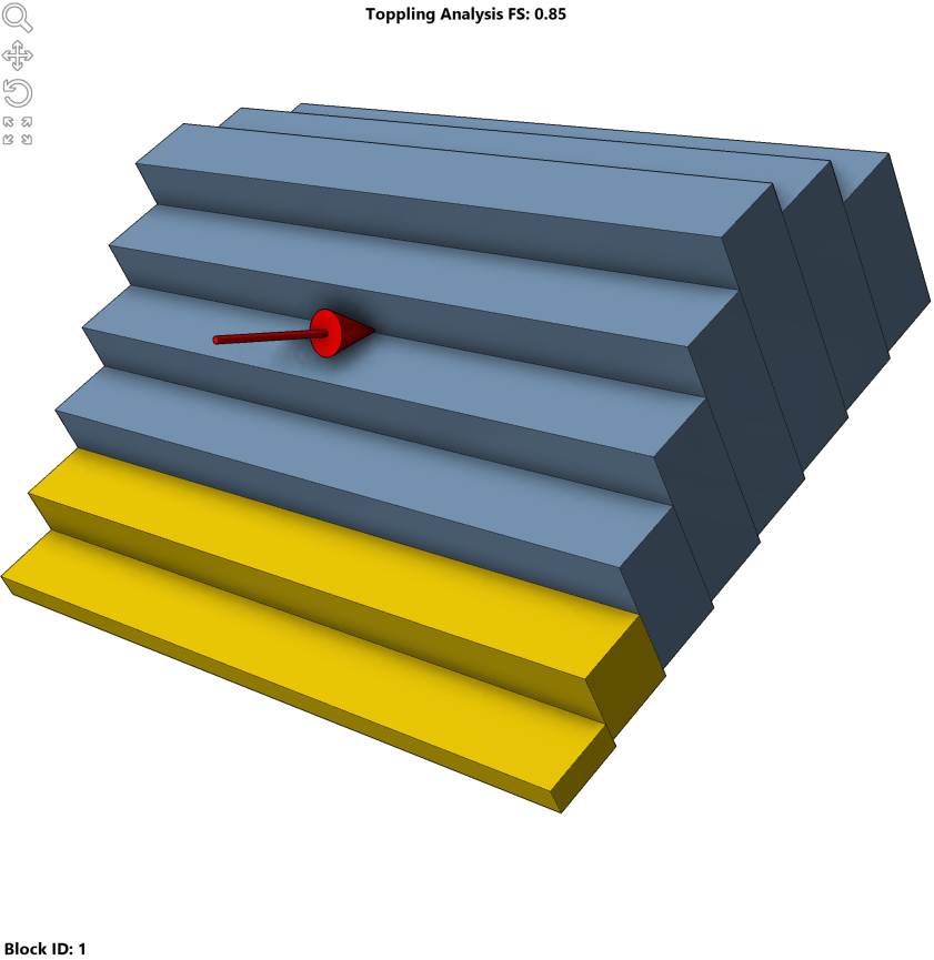
The display of Point Loads is dependent on the model. For Wedge and Planar models, Point Loads are represented as arrows at the center of the applied face. For a Toppling model, Point Loads are represented as arrows according to the Height Blow Crest or Horizontal Distance from Crest value, depending on the slope face they are applied to.
These arrows are symbolic and indicate the direction and existence of Point Loads. They do not indicate the magnitude of the forces. The display of these arrows can be turned on or off and the default arrow color can be changed in the Display Options dialog.

