Program Assumptions
There are some important limitations and assumptions of the RocSlope2 program that should be considered when modeling and interpreting the results.
RocSlope2 produces results for three Analysis Methods at once (Wedge, Planar, and Toppling) and assumes the following context given each of the different analyses:
Wedge Analysis
- Wedge Failure should be analyzed along slopes cut in hard rock where discontinuities are persistent and where stress-induced failure does not occur.
- All of the discontinuity surfaces are assumed to be perfectly planar.
- Displacements take place along the joints and blocks move as rigid bodies with no internal deformation or cracking.
- The Orientation of joints dictate possible Joint Intersections and formation of blocks. How and if joints intersect will determine if a block can form, its Geometry and dimensions (i.e., volume).
- The wedges are tetrahedral in nature and RocSlope2 computes the Factor of Safety for the translational slip of a tetrahedral wedge formed in a rock slope by two intersecting joints, the slope face, and the upper ground surface by default. Additional planes (Tension Crack / Basal Joint) can be added to analyze more complex wedge shapes.
- The discontinuities are considered to be ubiquitous: in other words, they can occur at any location in the rock mass.
- Without the consideration of external Loads and Supports, only gravitational loading due to self-weight is modeled as the driving force in limit equilibrium analysis to compute the Factor of Safety.
- Without the consideration of external Loads and Supports, only Shear Strength along sliding joints is modeled as the resisting force in limit equilibrium analysis to compute the Factor of Safety.
- RocSlope2 always initially calculates the maximum-sized wedges that can form on the slope face. To scale down the size of the wedges according to actual field observations (e.g., observed joint trace lengths), use the Scale Block options.
Planar Analysis
- Planar Failure should be analyzed along slopes cut in hard rock where discontinuities are persistent and where stress-induced failure does not occur.
- All of the discontinuity surfaces are assumed to be perfectly planar.
- The Orientation of joints dictate the formation of planar blocks. How and if joints intersect with the slope face will determine if a planar block can form, its Geometry and dimensions (i.e., volume).
- The discontinuities are considered to be ubiquitous: in other words, they can occur at any location in the rock mass.
- Without the consideration of external Loads and Supports, only gravitational loading due to self-weight is modeled as the driving force in limit equilibrium analysis to compute the Factor of Safety.
- Without the consideration of external Loads and Supports, only Shear Strength along sliding joints is modeled as the resisting force in limit equilibrium analysis to compute the Factor of Safety.
- RocSlope2 always initially calculates the maximum-sized planar blocks that can form on the slope face. To scale down the size of the blocks according to actual field observations (e.g., observed failure plane persistence), use the Scale Block options.
The following geometrical conditions are also assumed for a Planar Analysis:
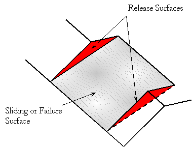
- A sliding or failure plane that strikes parallel or approximately parallel (within 20 degrees) to the face of the slope.
- The failure plane daylights into the face of the slope. This condition occurs when the failure surface dips at an angle shallower than the slope face.
- The presence of release surfaces at the lateral boundaries of the block that have insignificant resistance to sliding.

The limit equilibrium model in RocSlope2 assumes that all forces operating on a sliding block act through the centroid of the block; it ignores overturning moments.
While many planar block analysis programs consider only vertical tension cracks, RocSlope2 allows for non-vertical tension cracks as well. Non-vertical tension cracks in RocSlope2 can have angles of inclination from the horizontal that are less than 90 degrees.
Toppling Analysis
- Toppling Blocks are automatically generated based on the Slope Geometry and Block Generation Method (e.g., Equal Area), and it is assumed that the discontinuities are equally spaced. See the Toppling Settings topic for more information on the Block Generation Method.
- The base of each toppling block is assumed to be perpendicular to the Dip Angle of the block (i.e., all blocks are rectangular).
- Although the program considers Toppling, Sliding, and Flexure Toppling failure modes of individual blocks during the limit equilibrium calculations, keep in mind that the overall analysis is designed for toppling stability of rock slopes.