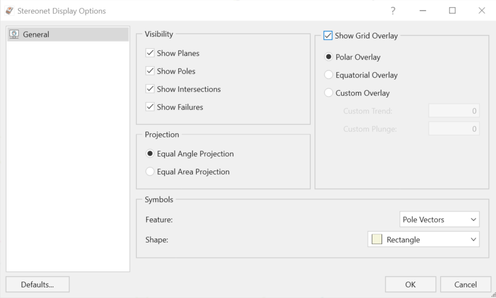
Stereonet Display Options
The Stereonet View can be adjusted using the Stereonet Display Options while the Stereonet View is active.
To access the Stereonet Display Options dialog:
- Select Home > Stereonet > Options

- The Stereonet Display Options dialog will open. Here, you can adjust Visibility, Grid Overlay, Projection and Symbols settings.

Visibility
Show Planes
The Show Planes option will display the planes as circles corresponding to the current orientations of the joints, slope, upper face and tension crack.
Show Poles
For a Probabilistic Analysis, the Show Poles option will display all randomly generated pole orientations for wedge planes with statistical distributions. The poles corresponding to the mean wedge, selected wedge or minimum wedge are also displayed.
Show Intersections
The Show Intersections option toggles the display of joint intersections on the stereonet. A joint intersection is the orientation of the line of intersection of two joint planes forming a wedge.
Show Failures
The Show Failures option highlights all intersections and corresponding joint poles, which represent a wedge with a safety factor <1. The Show Poles or Show Intersections options must also be selected in order for this option to apply. Failed orientations are highlighted in red.
Grid Overlay
A grid overlay can be applied to the Stereonet View by checking the Grid Overlay checkbox. Once enabled, the following options are available for a Grid Overlay:
- Polar Overlay
- Equatorial Overlay
- Custom Overlay (allows users to input custom Trend and Plunge values)
Symbols
The Symbols settings allow for further customization of the diagram. These settings allow users to select the shapes to display for each feature (Pole Vectors or Intersections).