Grouted Dowel
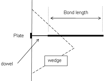
The Grouted Dowel bolt type can be used in RocSlope2 to model support that has a variable bonded (grouted) length, as shown in the figure below.

Tensile Capacity
The Tensile Capacity represents the maximum tensile capacity of the bolt itself (i.e., steel tensile capacity), independent of the plate capacity or the bond capacity. Units are Force.
Plate Capacity
The Plate Capacity is the maximum load that can be sustained by the plate assembly that connects the dowel to the exposed wedge face. Units are Force.
Bond Strength
The Bond Strength is expressed as a Force per unit Length, where the length refers to the length along the dowel. The maximum pullout force is therefore simply the Bond Length of the dowel, multiplied by the Bond Strength.
Bond Length
The bonded (grouted) length can be specified as either:
- A percentage of length
- Actual bond length
Bolt Force Diagram
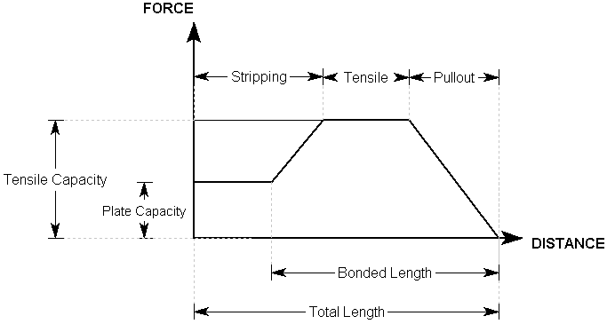
The Grouted Dowel tensile properties that are entered in the Bolt Properties dialog are used to determine a Bolt Force Diagram for the dowel, as illustrated below.
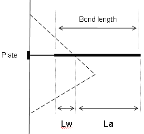
Consider a dowel that intersects a wedge as follows:

Lw = wedge length = bonded length of dowel within wedge
La = anchorage length = bonded length of dowel embedded in rock beyond wedge
Dowel Parameters
T = Tensile Capacity (force)
P = Plate Capacity (force)
B = Bond Strength (force / unit length of bond)
For a Grouted Dowel, at any point along the length of the dowel, there are three possible failure modes that are considered:
- Pullout - Force required to pull the anchorage length La of the bolt out of the rock
- Tensile Failure - Maximum axial capacity of the bolt
- Stripping - Wedge failure occurs, and bolt remains embedded in rock
The maximum force that can be mobilised by each failure mode, at any point along the bolt length, is given by the following equations:
Pullout: F1 = BLa Eqn.1
Tensile: F2 = T Eqn.2
Stripping: F3 = P + BLw Eqn.3
At any point along the length of the bolt, the force that is applied to the wedge by the bolt is given by the MINIMUM of these three forces.
Applied Force = min (F1, F2, F3) Eqn.4
A Bolt Force Diagram for a Grouted Dowel that exhibits all three failure modes is shown below. In this case, the Plate Capacity is less than the Tensile Capacity, and therefore Stripping is a possible failure mode. If the Plate Capacity is greater than the Tensile Capacity, Stripping cannot occur, and the Bolt Force Diagram is determined only by the Tensile and Pullout failure modes.

Bolt Orientation Efficiency
The Tensile Capacity determined from the Bolt Force Diagram assumes that a bolt is mobilized in pure tension. However, this is not usually the case, and a bolt that intersects a wedge may also be in shear or even compression.
A Bolt Orientation Efficiency factor (0 to 1) can be applied to the Tensile Capacity of the bolt determined from the Bolt Force Diagram. The efficiency factor accounts for the fact a bolt is not generally mobilized in pure tension but may include shear or compression.
See the Bolt Orientation Efficiency topic for more information.
Use Shear Strength
A bolt may also support a wedge by virtue of the shear strength of the bolt acting against the sliding direction of the wedge. Shear strength of a bolt may be considered in the analysis by selecting the Use Shear Strength check box in the Bolt Properties dialog and entering a value of shear strength.
Display of Bolt Force Diagrams
The Bolt Force Diagram for each bolt can be displayed directly on the model, as a display option. See the Bolt Force Diagram topic for more information.