User-Defined Bolt
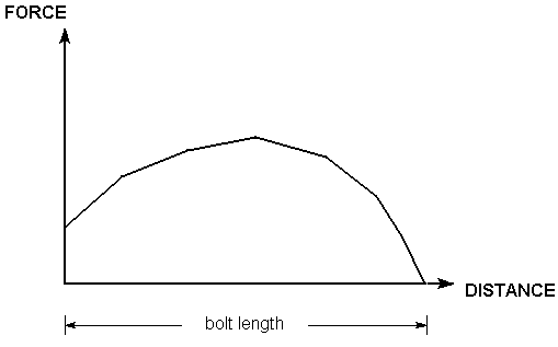
It is important to realise the Force Diagram (i.e. a plot of force versus distance along the length of the bolt) for each bolt is predicated on its pre-defined bolt type and its associated properties.
- Mechanically Anchored
- Grouted Dowel
- Cable Bolt
- Split Set / Swellex
The graph is generated based on the bolt properties which are entered. As far as the RocSlope2 Compute engine is concerned, the tensile support capacity at any point along the length of the bolt is entirely determined by the Force Diagram for the bolt.
If the properties of the pre-defined bolt types in RocSlope2 are not sufficient to generate a desired Force Diagram, then the user can simply define their own bolt type by creating an explicit Force Diagram. To do this:
- Select Support > Properties > Bolts

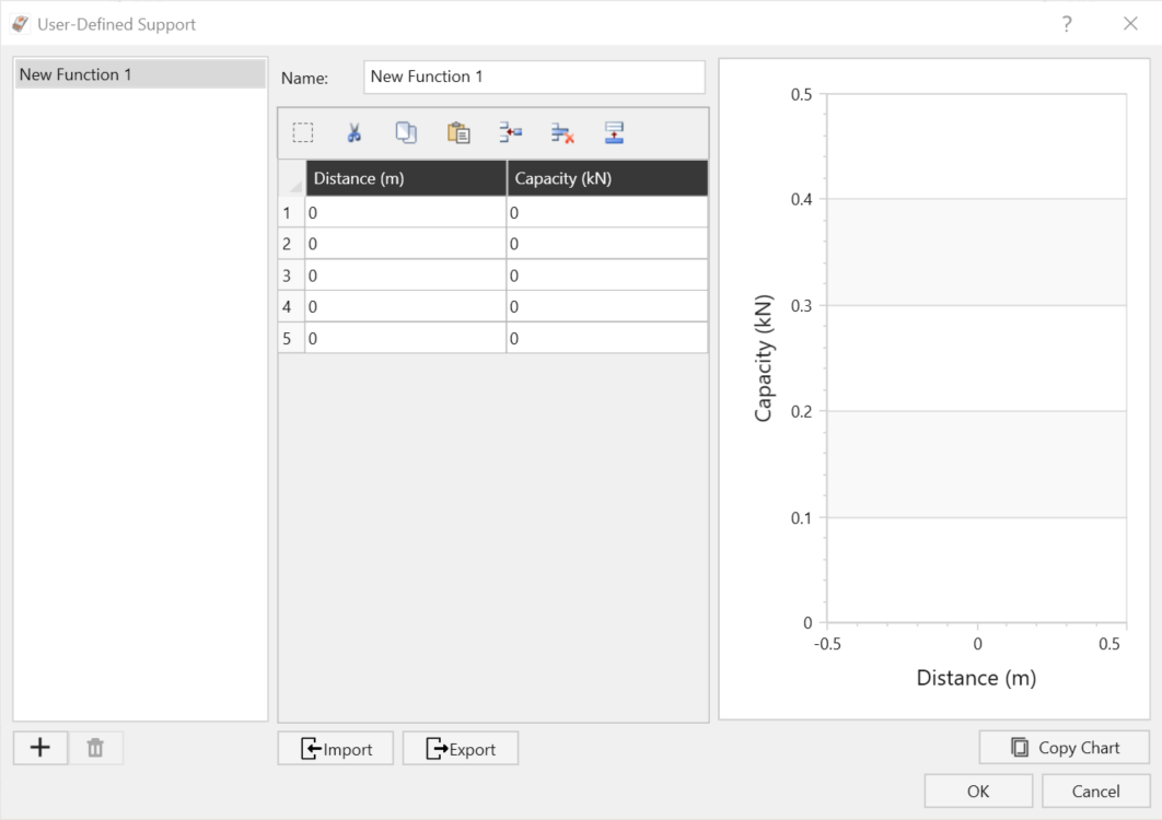
- In the Define Bolt Properties dialog, select User Defined from the drop-list of Support Types.
- Select the pencil icon
 next to User-Defined to open the dialog.
 - Enter values for Distance and Capacity (force) which define the Force Diagram for your support. As you enter the values, the graph at the right of the dialog will be updated to display the data you are entering.The first value for Distance should equal zero, and the final value should equal the length of your support.
- Enter a Name for the User Defined Support and select OK.
- The Name of the user defined support will now appear in the drop-list of User Defined Support Functions in the Bolt Properties dialog. The User Defined Support may now be used like any other bolt type, by first selecting User Defined from the list of bolt types, and then selecting the Name from the list of User Defined Support Functions.
- Any number of User Defined Support types may be defined, using steps 1 to 5.

An example of a user defined bolt force diagram is shown below.

Edit
You can edit an User Defined Support at any time, by selecting it from the User Defined Support Functions list in the Bolt Properties dialog, and then selecting the Edit button. You will see the User Defined Support dialog, in which you can edit the values defining the Force Diagram, or the Name.
Delete
To delete a User Defined Support type, select the Name from the User Defined Support Functions list in the Bolt Properties dialog, and select the Delete button.