Bolt Implementation
Some important assumptions when modeling Bolts in RocSlope2:
- For a bolt to have any effect on the block, the start of the bolt must intersect the daylighting free face (i.e., slope face) and the end of the bolt must intersect the joint face and extend through the block.
- The embedded length of the bolt inside the block is calculated as the distance between the intersection point of the bolt at the free surface to the intersection point of the bolt at the joint surface.
- The embedded length of the bolt outside the block is calculated as the distance between the intersection point of the bolt at the joint surface to the end of the bolt.
- Bolts can fail in one of six Bolt Failure Modes depending on which capacities are exceeded first. The limiting capacity controls the mode of failure.
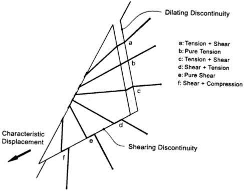
Bolt Deformation Mode
The bolt support force which is ultimately applied to a block, and the orientation of the applied force (tension or shear), depends on the following factors:
The Bolt Deformation Mode denotes the mode in which a bolt intersects a block failure plane. The deformation mode depends on whether the failure plane is a shear (sliding) plane or a dilating (opening) plane, and also on the orientation of the bolt with respect to the plane and the sliding direction.
There are six possibilities considered, as illustrated in the figure below.
Capacity and Orientation
- Bolts affect the Safety Factor through their Capacity and Orientation (Trend/Plunge). See Bolt Support Force for how bolt capacities are calculated.
- Bolt capacities and orientations are added vectorially. For Wedge and Planar Analyses, either the active or passive bolt model will apply. For Toppling Analysis, the bolt model is always passive.
- Multiple bolts with the same orientation can therefore be simulated by a single bolt having the same total capacity.
Length and Location
- If the Anchored Length of a bolt = 0 (i.e. it does not pass through the block), then the bolt will have NO effect on the model (i.e. its effective capacity will be zero).
- The Location of bolts (on the face of the block) has some effect on Safety Factor. Even though all forces in the block stability analysis are assumed to pass through the centroid of the block, the exact location of a bolt can affect the anchor length of the bolt. Where a selected bolt property type utilises anchor length for its bolt capacity calculations, the Factor of Safety can be affected.
Bolts vs. Point Loads
In the RocSlope2 analysis, external loads can be added in the form of active point loads which behave in a similar fashion to the addition of active rock bolts. This means that an External Load with the same orientation as a rock bolt, and with a Magnitude equal to the Capacity of the rock bolt, will have exactly the same effect on the Safety Factor, if the bolt model is active.
Bolt Patterns
A regular pattern of bolts can be applied to the slope face or upper slope face with the Add Bolt Pattern option. The pattern location, bolt length, spacing, orientation, and offset from origin can all be defined by the user.
Considerations for a Toppling Analysis
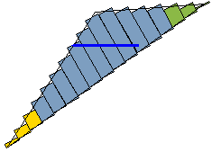
In order to be used in the Toppling Analysis, Spot Bolts and Bolt Patterns must cross the base plane of the toppling blocks (i.e. the anchor point must be within the rock mass beneath the toppling blocks). This is illustrated in the following figure.
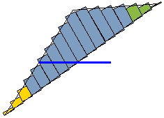
As illustrated in the following figure, if a bolt is anchored within the toppling blocks, by default it will have no effect on the Toppling Analysis, even though it can still impact the Wedge and Planar analysis results. If you want to include the support force of internal bolts in the RocSlope2 analysis, select the Internal bolts act as a force couple check box in the Toppling Settings tab of the Project Settings dialog.
Point Loads in a Toppling Analysis
Support forces can also be modelled as Point Loads applied to the slope surface. For a Toppling Analysis, a Point Load is equivalent to a Spot Bolt if the magnitude, angle and location are equivalent. This also applies if the Spot Bolt passes through the toppling blocks into the rock mass below (first case above). If a Spot Bolt terminates within the toppling blocks (second case above), a Point Load and Spot Bolt are not equivalent.
Active and Passive Bolt Models
In general terms, the Factor of Safety is defined as the ratio of the forces resisting motion, to the driving forces. Driving forces include the mass of the block accelerated through gravity, seismic forces, and water pressure. Resisting forces arise from the cohesion and frictional strength of the block sliding planes.
Active Support is included in Wedge and Planar Analyses as shown in Eqn. 1.
Where Tn is the normal component and Ts is the shear component of the force applied to the rock by the support.
Active Support is assumed to act in such a manner as to DECREASE the DRIVING FORCE in the Factor of Safety calculation. Tensioned cables or rock bolts, which exert a force on the block before any movement has taken place, could be considered as Active support.
Passive Support is included in the RocSlope2 analysis as shown in Eqn. 2.
By this definition, Passive Support is assumed to INCREASE the RESISTING FORCE provided by shear restraint, in the Factor of Safety equation.
Dowels or grouted cable bolts without tension, which only develop a resisting force after some movement of the block has taken place, could be considered as Passive support.
Since the exact sequence of loading and movement in a rock slope is never known in advance, the choice of Active or Passive bolt models is somewhat arbitrary. The user may decide which of the two models is more appropriate for the block being analyzed. In general, Passive support will always give a lower Factor of Safety than Active support.