3 - Water Pressure
1.0 Introduction
This tutorial demonstrates various options for modeling water pressure in RocSlope2. In RocSlope2, water pressure can exist on the slope faces when ponded water is present and/or on the internal joints when groundwater is present.
Water pressure can be modelled in following ways in RocSlope2:
- Ponded Water Pressure: Applied to slope faces.
- Groundwater Pressure: Applied to internal joints.
Topics Covered in this Tutorial:
- Groundwater Methods
- Ponded Water Pressure
- Water Pressure Contours
Finished Product:
The finished product of this tutorial can be found in Tutorial 3 Water Pressure (final).rocslope2 file, located in the Examples > Tutorials folder in your RocSlope2 installation folder.
2.0 Base File and Model Input Data
- If you have not already done so, run the RocSlope2 program by double-clicking the RocSlope2 icon in your installation folder or by selecting Programs > Rocscience > RocSlope2 in the Windows Start menu.
- Select File > New Project

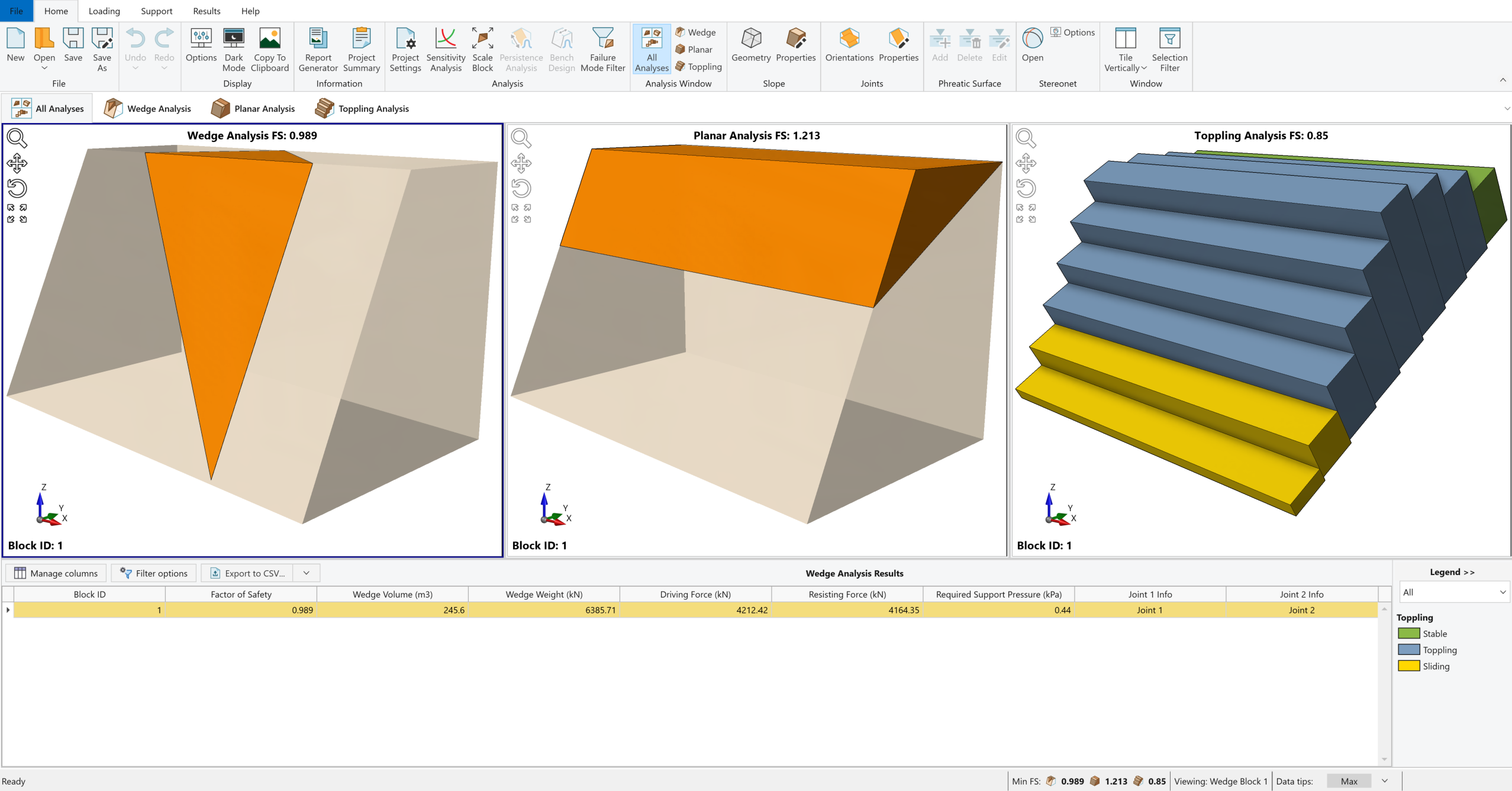
Whenever a new file is created, the default input data forms valid slope geometries for wedge, planar and toppling analysis, as shown in the image below.
This tutorial will use Tutorial 3 – Water Pressure (initial).rocslope2 file as a base model, which is the output model of Tutorial 1 – Quick Start.
- Select File > Open Project

- Open the Tutorial 3 - Water Pressure (initial).rocslope2 file.
This will open the base file.
2.1 Project Settings
Before we start, we'll make sure Project Settings are the way we want them.
- Select Home > Analysis > Project Settings

- In the Units tab, make sure Units = Metric, stress as kPa.
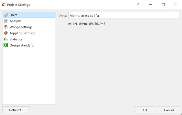
RocSlope2 Project Settings dialog – Units tab - Under the Analysis tab, ensure that all Analysis methods (Wedge, Planar and Toppling) are selected.
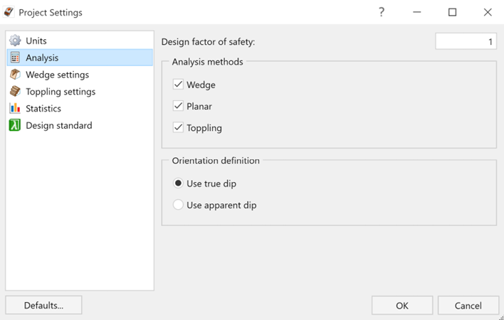
RocSlope2 Project Settings dialog – Analysis tab - Under the Statistics tab, ensure that analysis type is Deterministic.
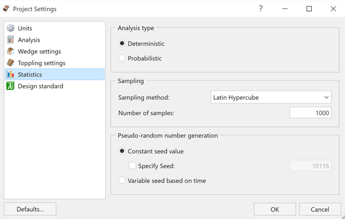
RocSlope2 Project Settings dialog – Statistics tab
2.2 Slope Geometry
The Slope Geometry dialog is used for entering slope geometry data in RocSlope2.
- Select Home > Slope > Geometry

- Ensure that Origin Point, which is located at the mid-point of the slope crest and is used to position the slope within the space, is X=0, Y=0 and Z=0. This will be useful when defining groundwater by elevation.
- The following data is expected in the base file.
| Slope Face | |
| Slope Face Dip (°) | 70 |
| Slope Face Dip Direction (°) | 45 |
| Height (m) | 20 |
| Overhanging | No |
| Use Default length | No |
| Length (m) | 50 |
| Upper Face | |
| Dip (°) | 5 |
| Dip Direction (°) | 45 |
| Use Default Bench Width | Yes |
| Overall Base Inclination (for Toppling) | |
| Overall Base Inclination / Dip (°) | 42 |
| Tension Crack Exists | No |
2.3 Joint Properties
- Select Home > Joints > Properties

- Ensure the Joint Property 1 data is as follows:
- Cohesion (kPa) = 0
- Phi (º) = 35
- Waviness (º) = 0
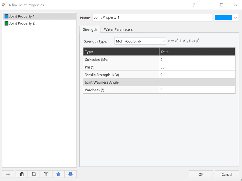
Joint Properties Input Data dialog – Joint Property 1 Strength
- Cohesion (kPa) = 0
- Under the Water Parameters tab, and ensure that Apply Groundwater checkbox is selected so when we define the groundwater in the following chapters of this tutorial, it applies to Joint 1.
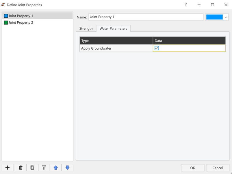
Joint Properties Input Data dialog – Joint Property 1 Water Parameters - Select Joint Property 2 and ensure the data is as follows:
- Cohesion (kPa) = 5
- Phi (º) = 32
- Waviness (º) = 2
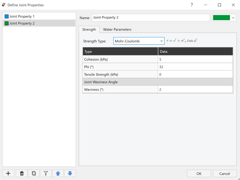
Joint Properties Input Data dialog – Joint Property 2 Strength
- Cohesion (kPa) = 5
- Under the Water Parameters tab, ensure that Apply Groundwater checkbox is selected so when we define the groundwater in the following chapters of this tutorial, it applies to Joint 2.
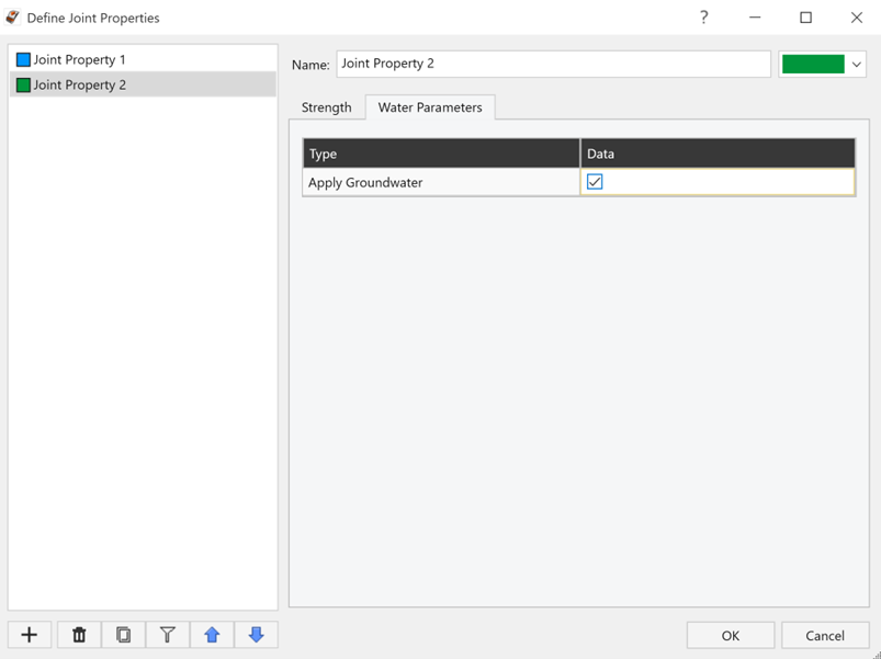
Joint Properties Input Data dialog – Joint Property 2 Water Parameters - Click OK to close the dialog.
2.4 Joint Orientations
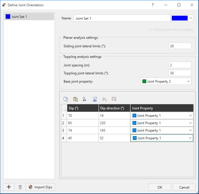
- Select Home > Joints > Orientations

- Ensure the Sliding and Toppling lateral limits are as follows:
- Under Toppling Analysis Settings, make certain that the Joint Spacing = 2 and Base Joint Property = Joint Property 2.
- Ensure that the Joint Orientation input data is as follows:
- Click OK to close the dialog.
| Joint No | Dip (°) | Dip Direction (°) | Joint Property |
| 1 | 70 | 14 | Joint Property 1 |
| 2 | 65 | 220 | Joint Property 1 |
| 3 | 74 | 145 | Joint Property 1 |
| 4 | 45 | 52 | Joint Property 1 |
3.0 Groundwater Methods
There are three different Groundwater Definition Methods in RocSlope2. One of the following three groundwater definition methods can be selected from the Groundwater Method dropdown in the Water Parameters tab of the Slope Properties dialog.
- Elevation: Groundwater level is defined using an elevation. Hydrostatic forces are applied to all block joint surfaces below the user-defined elevation.
- Water Surface: Groundwater level is defined using a user drawn phreatic surface. Hydrostatic forces are applied to all block joint surfaces below the phreatic surface.
- Custom Pressure: Used to specify an actual average constant water pressure along each joint plane.
3.1 Adding Groundwater to the Model using Elevation
To add groundwater using Elevation:
- Select Home > Slope > Properties

- Go to the Water Parameters tab.
- Select the Groundwater Method drop-down and set Groundwater Method = Elevation.
- Set the following groundwater parameters:
- Groundwater Elevation (m) = -5
- Water Unit Weight (kN/m3) = 9.81
- Groundwater Elevation (m) = -5
- Click OK to apply the changes and close the dialog.
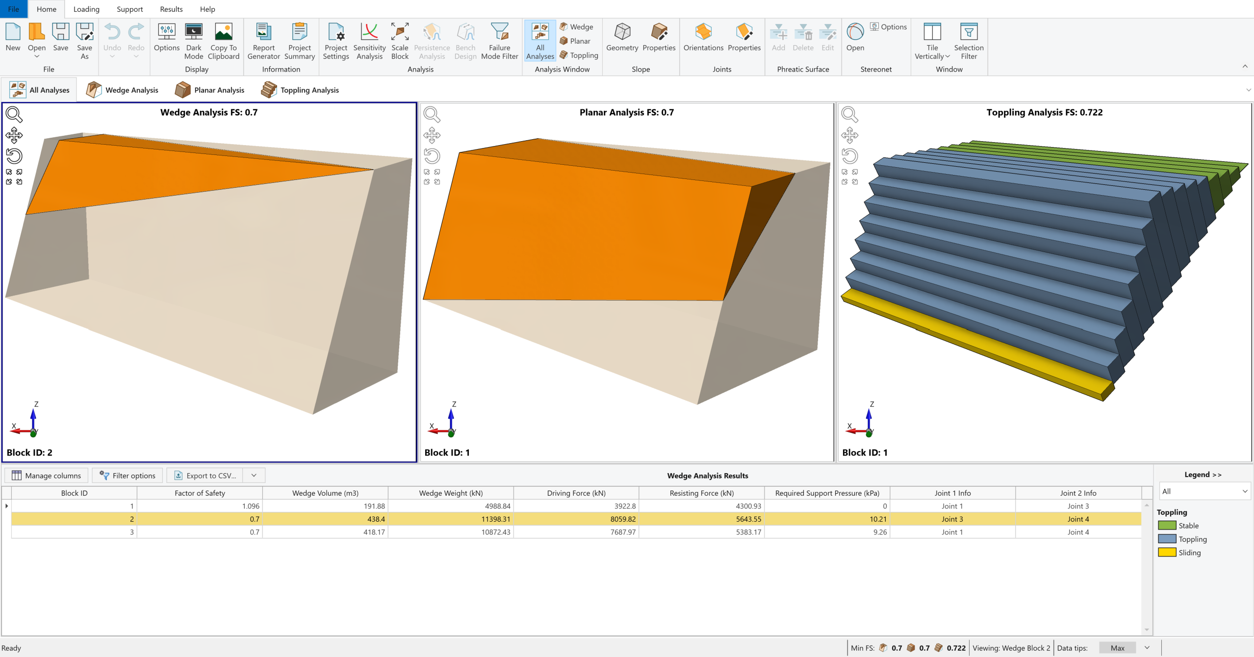
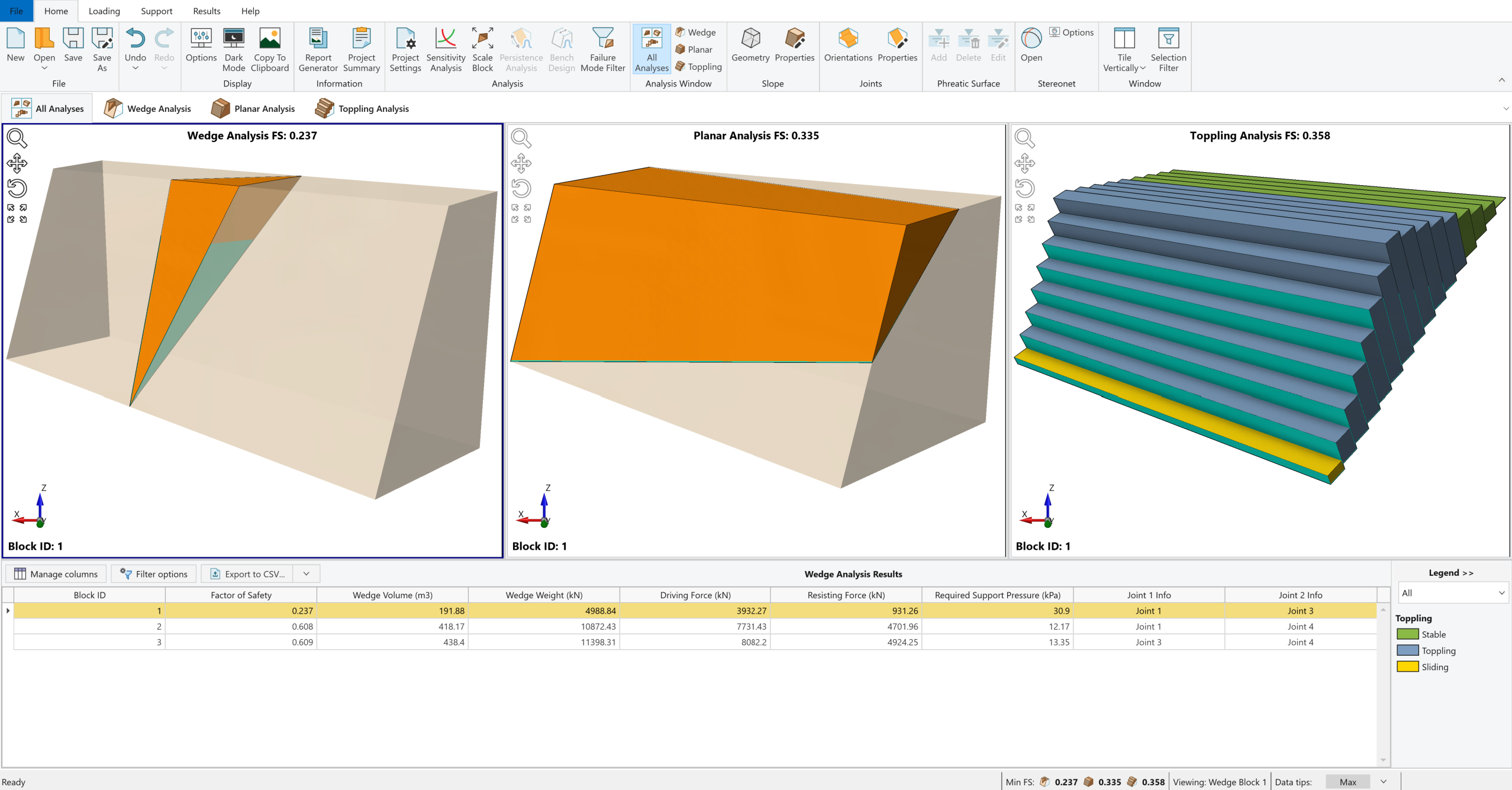
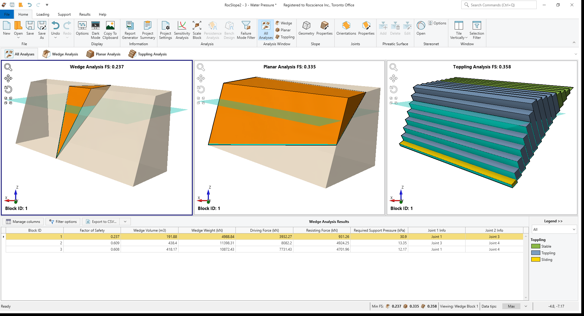
Notice that the Factor of Safety (FS) for Wedge, Planar and Toppling Analyses are computed instantly with groundwater. The lowest Factor of Safety and the corresponding Block ID and Geometry are displayed at each analysis pane for the corresponding analysis method.
Notice that the Factor of Safety for Wedge Analysis Block ID=1 decreased to 0.237 from 1.096 (in dry conditions), and it is now the block with lowest FS for Wedge Analysis. Also, Factor of Safety values decreased to 0.335 for Planar Analysis and to 0.358 for Toppling Analysis.
You can also follow the wetted areas along the joints for each analysis in the corresponding analysis display.
3.2 Adding Groundwater to the Model using Water Surface
To add groundwater using Water Surface:
- Select Home > Slope > Properties
- Go to the Water Parameters tab.
- Select the Groundwater Method drop-down and set Groundwater Method = Water Surface.
- Click OK to apply the changes and close the dialog.
Now that the groundwater method is set as water surface, we need to define the water level by drawing a phreatic surface. Phreatic surface can be added in any of the 2D views, and it will be applied to all analyses.
- Double-click on the Wedge Analysis display pane to open 3D Wedge View.
- Click on Views > 2D to display the 2D Wedge View.
- Select Home > Phreatic Surface > Add
 to start adding the phreatic surface.
 - Notice that the cursor has changed to enable drawing in 2D Wedge View.
- Press 't' (t=table) on your keyboard to open Edit Coordinates table and to add the Phreatic Surface using X-Y coordinates.
- Enter the following X and Y values.
- X = -10, Y = -5
- X = 15, Y = -5
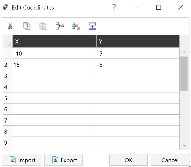
- X = -10, Y = -5
- Click OK to accept the entered values and close the dialog.
- The drawn phreatic surface is now displayed in both 2D and 3D Wedge Views.
- Check 2D and 3D Planar and Toppling Views to ensure that the drawn phreatic surface is displayed, extends through the slope and applied in all views.
Notice that the Factor of Safety (FS) for Wedge, Planar and Toppling Analyses are computed instantly with groundwater surface. The lowest Factor of Safety and the corresponding Block ID and Geometry are displayed at each analysis pane for the corresponding analysis method.
Since we applied the same water level that we defined using elevation the Factor of Safety for Wedge Analysis Block ID=1 decreased to 0.237 from 1.096 (in dry conditions), and it is now the block with lowest FS for Wedge Analysis. Also, Factor of Safety values decreased to 0.335 for Planar Analysis and to 0.358 for Toppling Analysis.
You can also follow the wetted areas along the joints for each analysis in the corresponding analysis display.
4.0 Ponded Water Pressure
Ponded Water can be applied to the slope faces in the Water Parameters tab of the Slope Properties dialog. Ponded water level is defined using an elevation and hydrostatic forces are applied to all slope faces below the user-defined elevation.
4.1 Adding Ponded Water
- Select Home > Slope > Properties
- Go to the Water Parameters tab.
- Select the checkbox next to Apply Ponded Water.
- Set the following ponded water parameters:
- Ponded Water Elevation (m) = -10
- Ponded Water Unit Weight (kN/m3) = 9.81
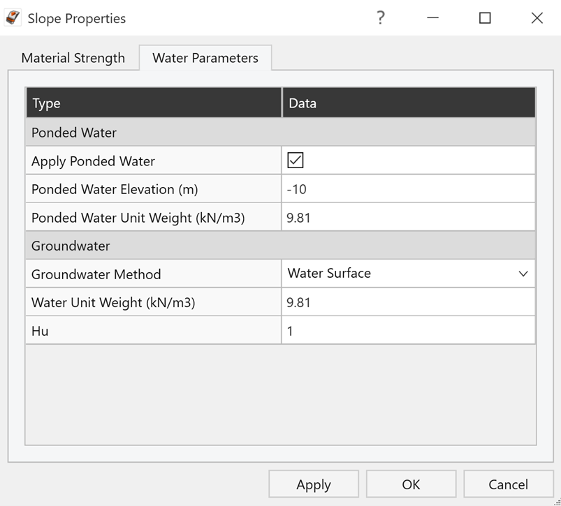
- Ponded Water Elevation (m) = -10
- Click OK to apply the changes and close the dialog.
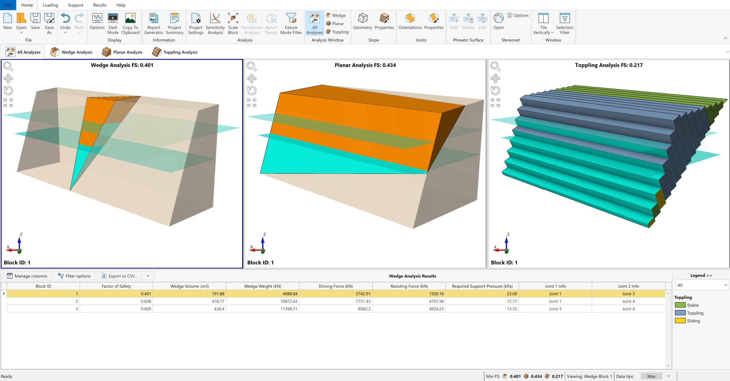
- Notice that applied ponded water is now displayed in all analyses views and applied to all analyses.
Notice that the Factor of Safety increases to 0.401 for Wedge analysis and 0.434 for Planar Analysis. In this case, the ponded water is acting as a stabilizing force on the blocks. The Factor of Safety decreases to 0.217 for Toppling Analysis.
You can also follow the wetted areas on the slope faces for each analysis in the corresponding analysis display.
5.0 Water Pressure Contours
To view water contours on the display:
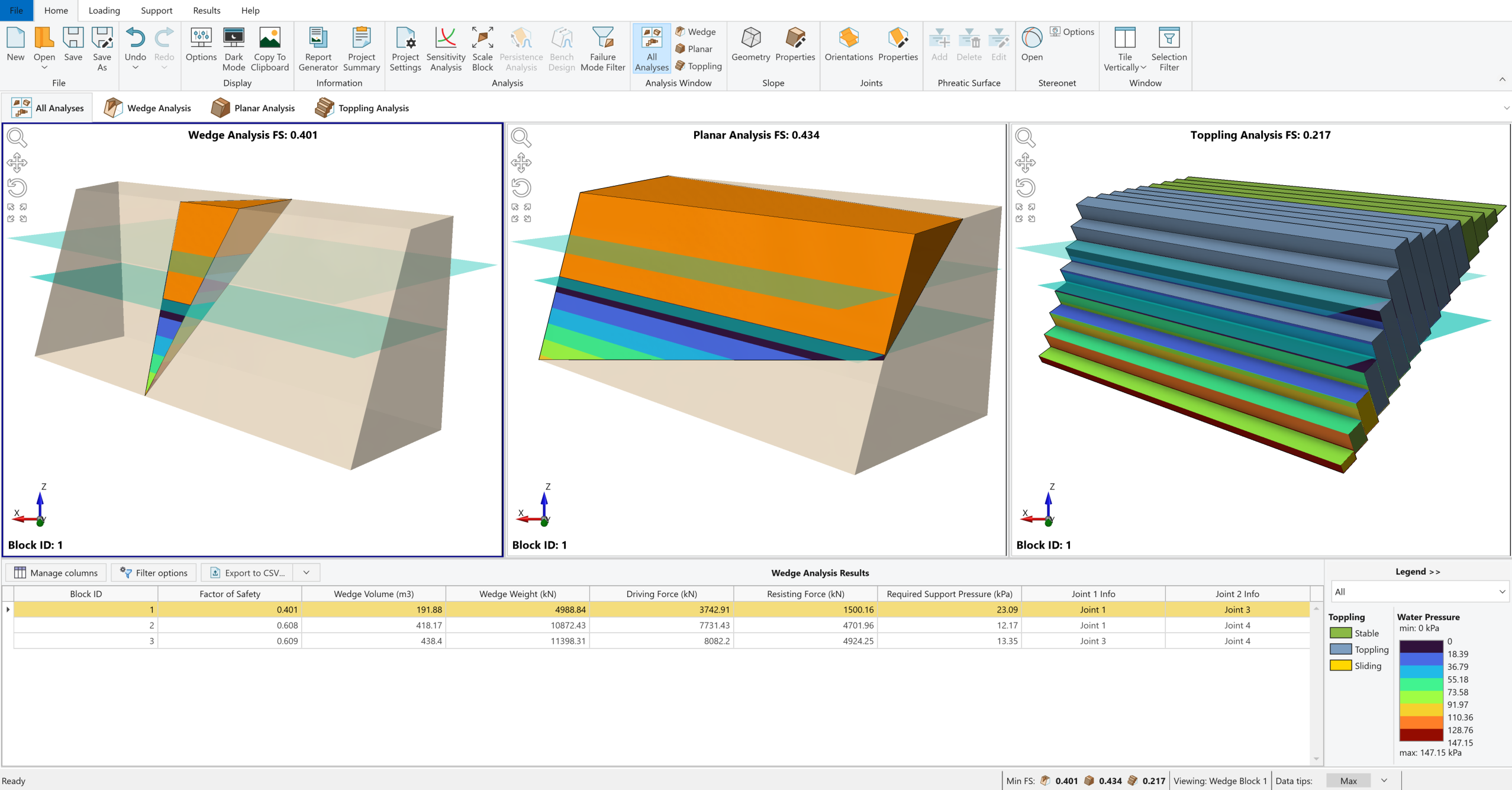
- Select Results > Contours > Show Water Contour

This will display the water contours along the joints and on the slope faces. Notice how the pressure contours are parallel to the water surfaces.
The water pressure contour legend is also shown in the legend at the lower right corner by default when water contours are displayed.
This concludes the tutorial. You are now ready to proceed to the next tutorial, Tutorial 4 – Loading and Supports.