4 - Support
1.0 Introduction
This tutorial demonstrates the various ways of modelling support to increase the model's Factor of Safety. All the methods of modelling support in RocSlope2 simply represent different ways of applying a force to a block.
- Bolt Patterns and Spot Bolts can be added with the Add Bolt option.
- Shotcrete can be applied with the Shotcrete option.
- A support or loading pressure can be applied with the Pressure option.
- External Forces can be applied with the Point Load option.
- Seismic Load can also be applied to a block as a force with the Seismic Load option.
Topics Covered in this Tutorial:
- Bolt Patterns
- Bolt Force Diagrams
- Shotcrete
- Pressure
- Spot Bolt
- Point Load
- Seismic Load
Finished Product:
The finished product of this tutorial can be found in Tutorial 4 Support (final).rocslope2 file, located in the Examples > Tutorials folder in your RocSlope2 installation folder.
2.0 Base File and Model Input Data
- If you have not already done so, run the RocSlope2 program by double-clicking the RocSlope2 icon in your installation folder or by selecting Programs > Rocscience > RocSlope2 in the Windows Start menu.
- Select File > New Project

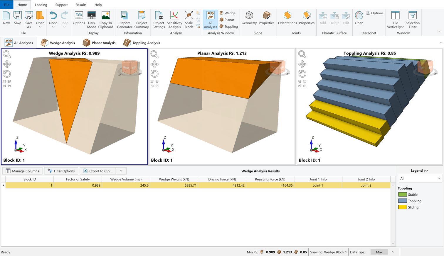
Whenever a new file is created, the default input data forms valid slope geometries for wedge, planar and toppling analysis, as shown in the image below.
This tutorial will use Tutorial 4 – Support (initial).rocslope2 file as a base model, which is the output model of Tutorial 1 – Quick Start.
- Select File > Open Project

- Open Tutorial 4 - Support (initial).rocslope2 file.
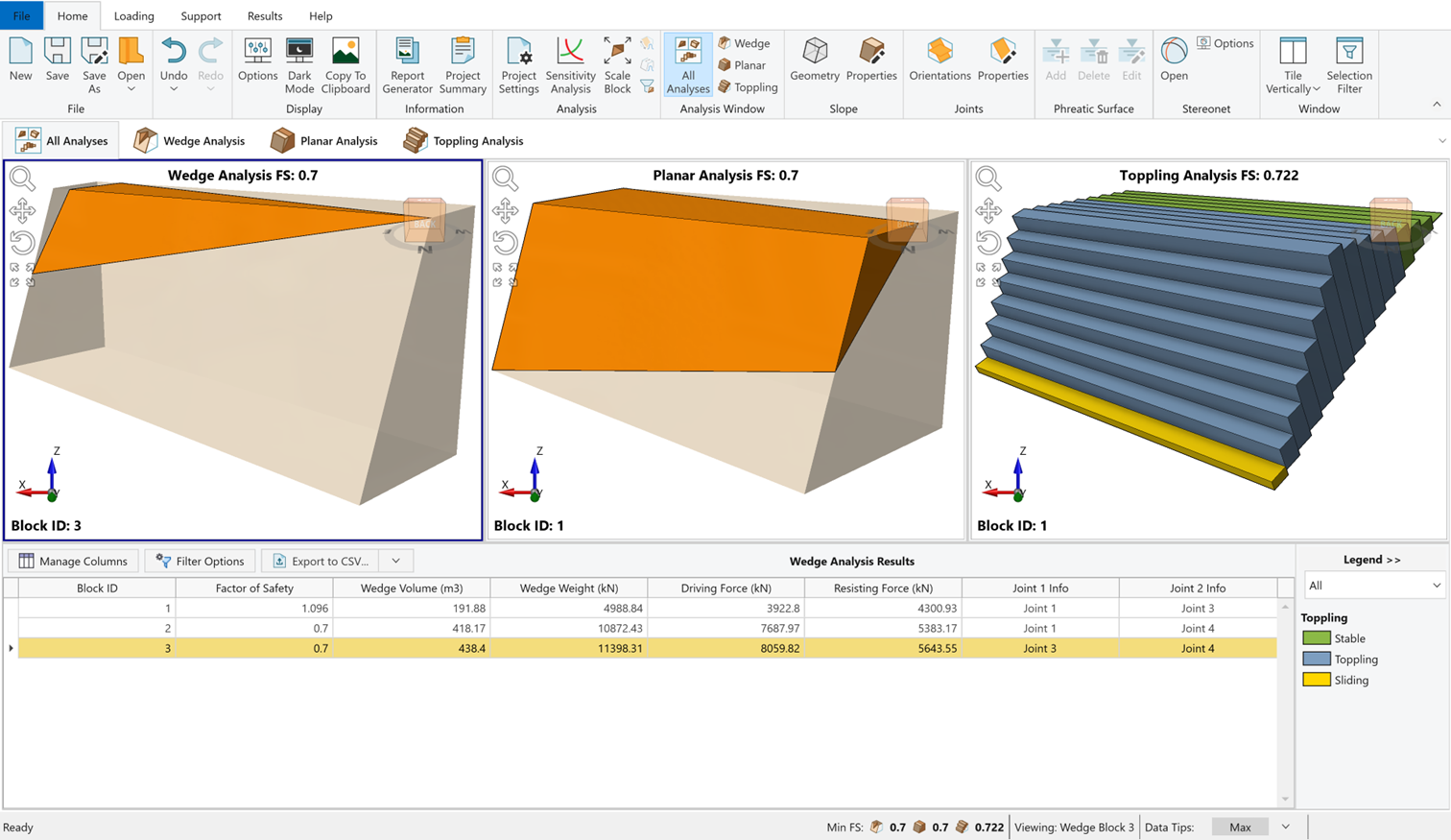
This will open the base file.
2.1 Project Settings
In this tutorial, units are set to Metric, stress as kPa, and the settings are configured to perform Deterministic Analysis for all three failure modes: Wedge, Planar, and Toppling.
2.2 Slope Geometry
- Select Home > Slope > Geometry

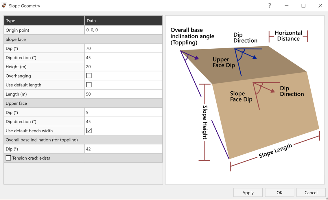
- The following data is expected in the base file.
Slope Face Slope Face Dip (°) 70 Slope Face Dip Direction (°) 45 Height (m) 20 Overhanging No Use Default Length No Length (m) 50 Upper Face Dip (°) 5 Dip Direction (°) 45 Use Default Bench Width Yes Overall Base Inclination (for Toppling) Overall Base Inclination / Dip (°) 42 Tension Crack Exists No
2.3 Slope Properties
The Slope Properties dialog is used for entering the data for Rock Unit Weight, Water Parameters and Rock Material Strength if the Block Flexure Toppling is enabled.
- Select Home > Slope > Properties

- Under the Material Strength tab, ensure that Unit Weight = 26kN/m3 .
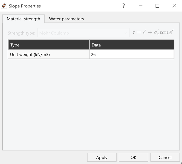
- Click OK to close the dialog.
2.4 Joint Properties
- Select Home > Joints > Properties

- Ensure the Joint Property 1 data is as follows:
- Cohesion (kPa) = 0
- Phi (º) = 35
- Waviness (º) = 0
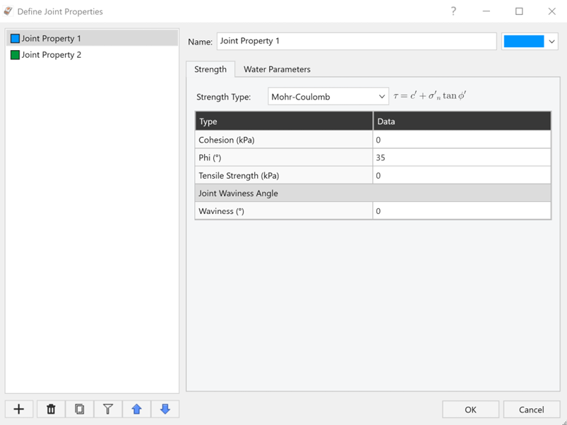
Joint Properties Input Data dialog – Joint Property 1 Strength
- Cohesion (kPa) = 0
- Select Joint Property 2 and ensure the data is as follows:
- Cohesion (kPa) = 5
- Phi (º) = 32
- Waviness (º) = 2
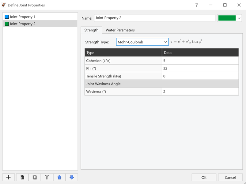
Joint Properties Input Data dialog – Joint Property 2 Strength
- Cohesion (kPa) = 5
- Click OK to close the dialog.
2.5 Joint Orientations
- Select Home > Joints > Orientations

- Ensure the Sliding and Toppling lateral limits are as follows:
- Sliding Joint Lateral Limits = 20
- Toppling Joint Lateral Limits = 30
- Make certain that, under Toppling Analysis Settings, the Joint Spacing = 2 and Base Joint Property = Joint Property 2.
- Ensure that the Joint Orientation input data is as follows:
Joint No Dip (°) Dip Direction (°) Joint Property 1 70 14 Joint Property 1 2 65 220 Joint Property 1 3 74 145 Joint Property 1 4 45 52 Joint Property 1 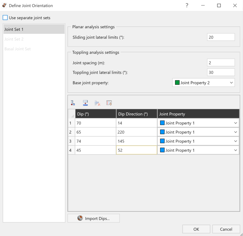
Joint Orientation Input Data dialog - Click OK to close the dialog.
3.0 Adding Bolt Pattern
We'll start by adding a bolt pattern to the blocks using the Add Bolt Pattern option.
3.1 Bolt Properties
We first need to set up bolt properties using the Define Bolt Properties dialog.
- Select Support > Properties > Bolts

- Select Bolt Property 1.
- Set Support Type = Simple Bolt Force.
- Set Force Application = Active.
- Set Force = 100kN.
- Click OK to apply changes and close the dialog.
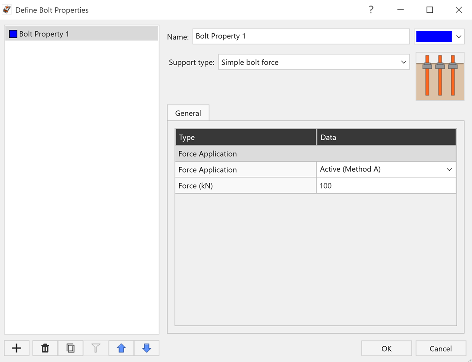
Define Bolt Properties dialog
3.2 Adding Bolt Pattern
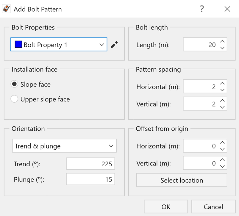
Next, we will add the bolt pattern to the blocks using the Add Bolt Pattern dialog.
- Select Support > Bolt Patterns > Add

- Keep Bolt Properties = Bolt Property 1.
- Keep Installation Face = Slope Face.
- Set Orientation = Trend & Plunge and enter the following values:
- Trend = 225
- Plunge = 15
- Set Bolt Length = 20.
- Set Pattern Spacing as follows:
- Horizontal = 2
- Vertical = 2
- Horizontal = 2
- Keep Offset from Origin values as is.
- Click OK to accept the changes and apply the bolt pattern.
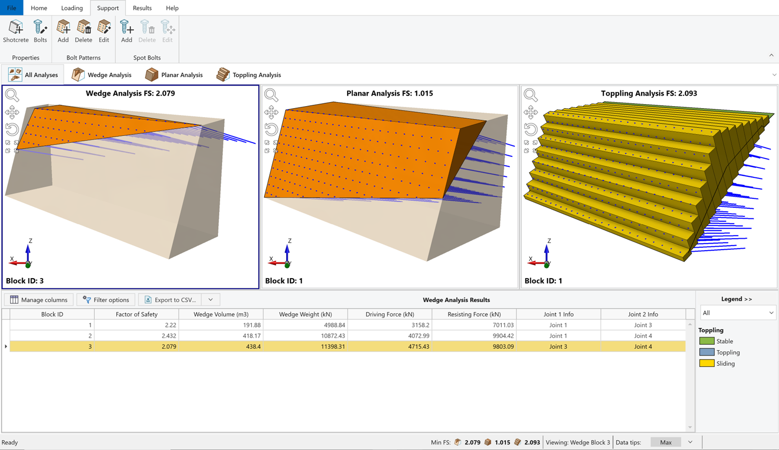
Notice that the defined bolt pattern is applied in all analysis views and Factor of Safety (FS) values are computed instantly for Wedge, Planar and Toppling analyses. The lowest Factor of Safety and the corresponding Block ID and Geometry are displayed at each analysis pane for the corresponding analysis method.
Notice that the lowest Factor of Safety increased to 2.079 for Wedge Analysis, 1.015 for Planar Analysis and 2.093 for Toppling Analysis.
TIP: Note that the color of the bolt pattern on the model matches the color of its Bolt Property in the Bolt Properties dialog.
TIP: Multiple bolt patterns can be added to the model.
3.3 Bolt Force Diagram
The Toggle Force Diagrams Visibility option can display force diagrams for bolt elements. A bolt force diagram describes the available force that a given bolt element mobilizes along its length.
- Select Results > Force Diagrams > Toggle Visibility

- The support forces are displayed on the model as shown below.
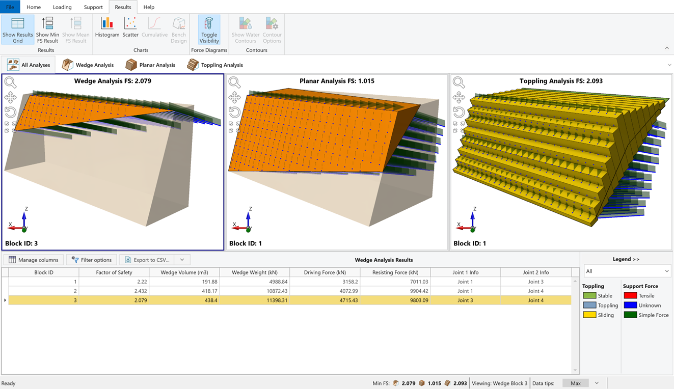
When bolt forces are displayed, a Support Force Legend appears at the bottom right corner of the viewing window. The legend indicates the failure mode(s) along the bolt length.
The Force Diagram and the point of intersection of a joint with a bolt element determines the force magnitude applied to the joint by this bolt element.
Click on Toggle Visibility again to turn off the Force Diagram visibility.
3.4 Editing Bolt Pattern
You can edit the properties of a bolt pattern using the Edit Bolt Pattern option.
- Select Support > Bolt Patterns > Edit

- Click on any bolt in any analysis view to select the bolt pattern. The bolt pattern changes color to indicate it's selected.
- Press Enter to open Edit Bolt Pattern dialog.
- Change Pattern Spacing as follows:
- Horizontal = 1.5
- Vertical = 1.5
- Horizontal = 1.5
- Click OK to accept the changes and close the dialog.
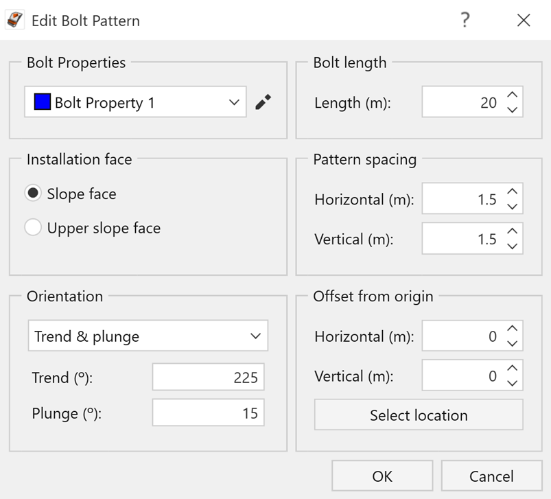
Notice that the changed bolt pattern spacing is applied in all analysis views and Factor of Safety (FS) values are computed instantly again for Wedge, Planar and Toppling analyses. The lowest Factor of Safety now increased to 3.781 for Wedge Analysis, 1.32 for Planar Analysis and 2.899 for Toppling Analysis.
3.5 Deleting Bolt Pattern
You can delete bolt patterns from a model using the Delete Bolt Pattern option.
To delete one or more bolt patterns from a model:
- Select Support > Bolt Patterns > Delete

- Click on any bolt in any analysis view to select the bolt pattern. The bolt pattern changes color to indicate it's selected.
- Press Enter to delete the Bolt Pattern.
Note that a new Factor of Safety is immediately calculated.
4.0 Adding Shotcrete
You can add shotcrete support to a model using the Shotcrete option. To open the Shotcrete dialog:
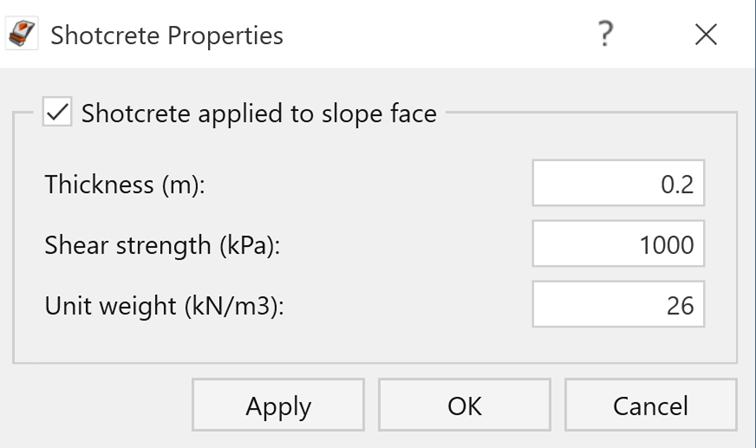
- Select Support > Properties > Shotcrete

- Select the Shotcrete Applied to Slope Face checkbox.
- Set Thickness (m) = 0.2.
- Keep Shear strength (kPa) = 1000 and Unit weight (kN/m3) = 26.
- Click OK to accept the changes and close the dialog.
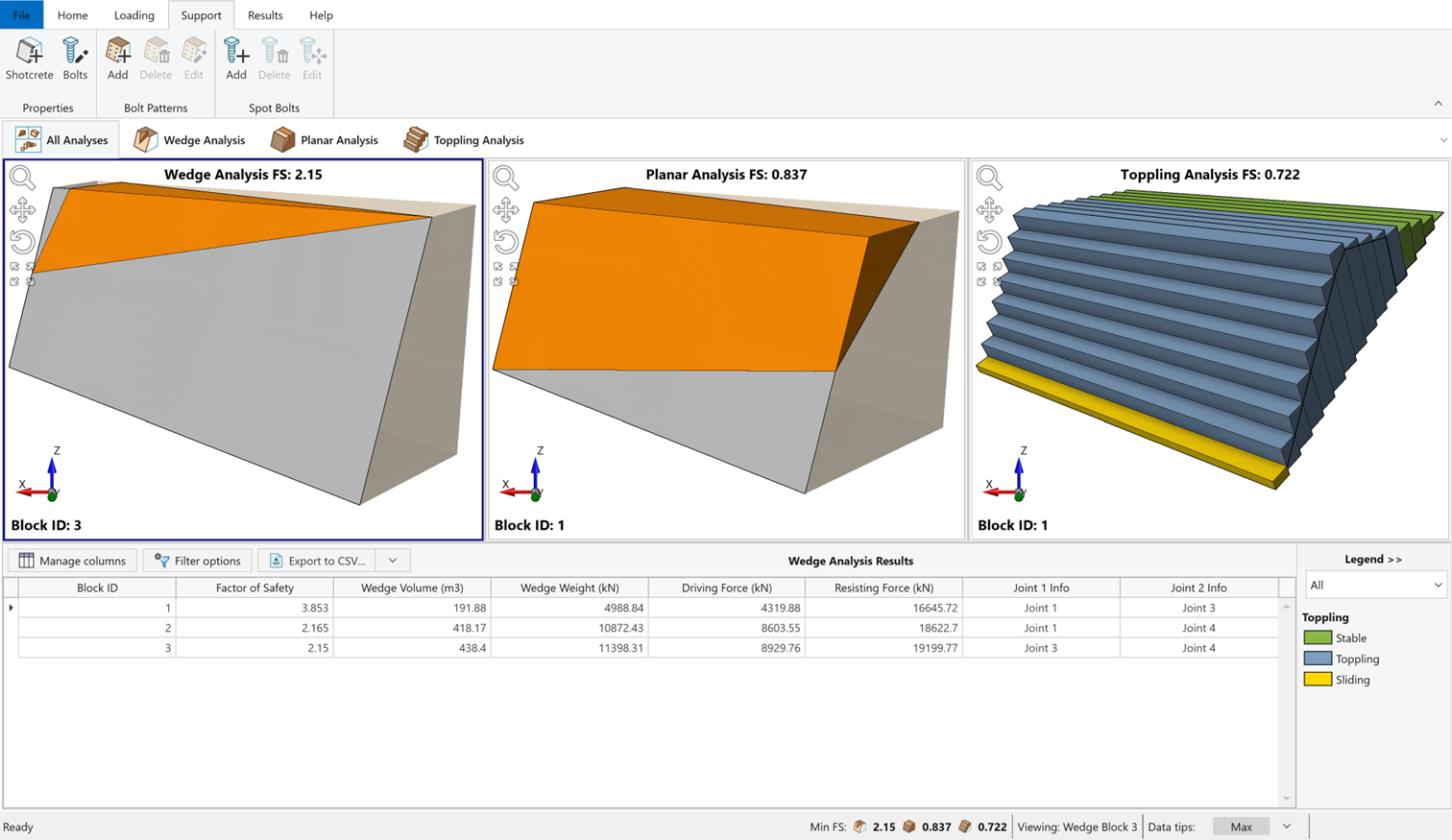
Notice that the addition of the shotcrete layer has increased the lowest Factor of Safety to 2.15 for Wedge Analysis and to 0.837 for Planar Analysis.
TIP: To perform a parametric analysis and view the effect of different Thickness, Shear Strength and Unit Weight parameter values, you can click the Apply button to re-compute the analysis without closing the dialog.
- Shotcrete can be removed by de-selecting Shotcrete Applied to Slope Face checkbox in the Shotcrete Properties dialog. Remove the Shotcrete before continuing further.
5.0 Pressure Support
Next, we will look at adding support to a block using the Pressure option. Before continuing, ensure that bolts and shotcrete are deleted from the model following instructions in the sections above.
To open the Pressure Loading dialog:
- Select Loading > Define Loads > Pressure

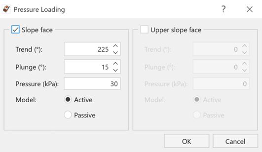
- Select the Slope Face checkbox to apply pressure to the slope face only.
- Set Orientation = Trend & Plunge and enter following values:
- Trend = 225
- Plunge = 15
- Trend = 225
- Set Pressure (kPa) = 30.
- Keep Model = Active.
- Click OK to apply the pressure loading and close the dialog.
Notice that the defined pressure loading is applied in all analysis views and Factor of Safety (FS) values are computed instantly for Wedge, Planar and Toppling analyses. The lowest Factor of Safety and the corresponding Block ID and Geometry are displayed at each analysis pane for the corresponding analysis method.
The lowest Factor of Safety now increased to 2.146 for Wedge Analysis, 1.064 for Planar Analysis and 1.264 for Toppling Analysis.

- Pressure loading can be removed by de-selecting the Slope Face check box in the Pressure Loading dialog. Remove the Pressure Loading before continuing further.
6.0 Equivalence of Support Methods in RocSlope2
We will now demonstrate the equivalence of the various support methods in RocSlope2.
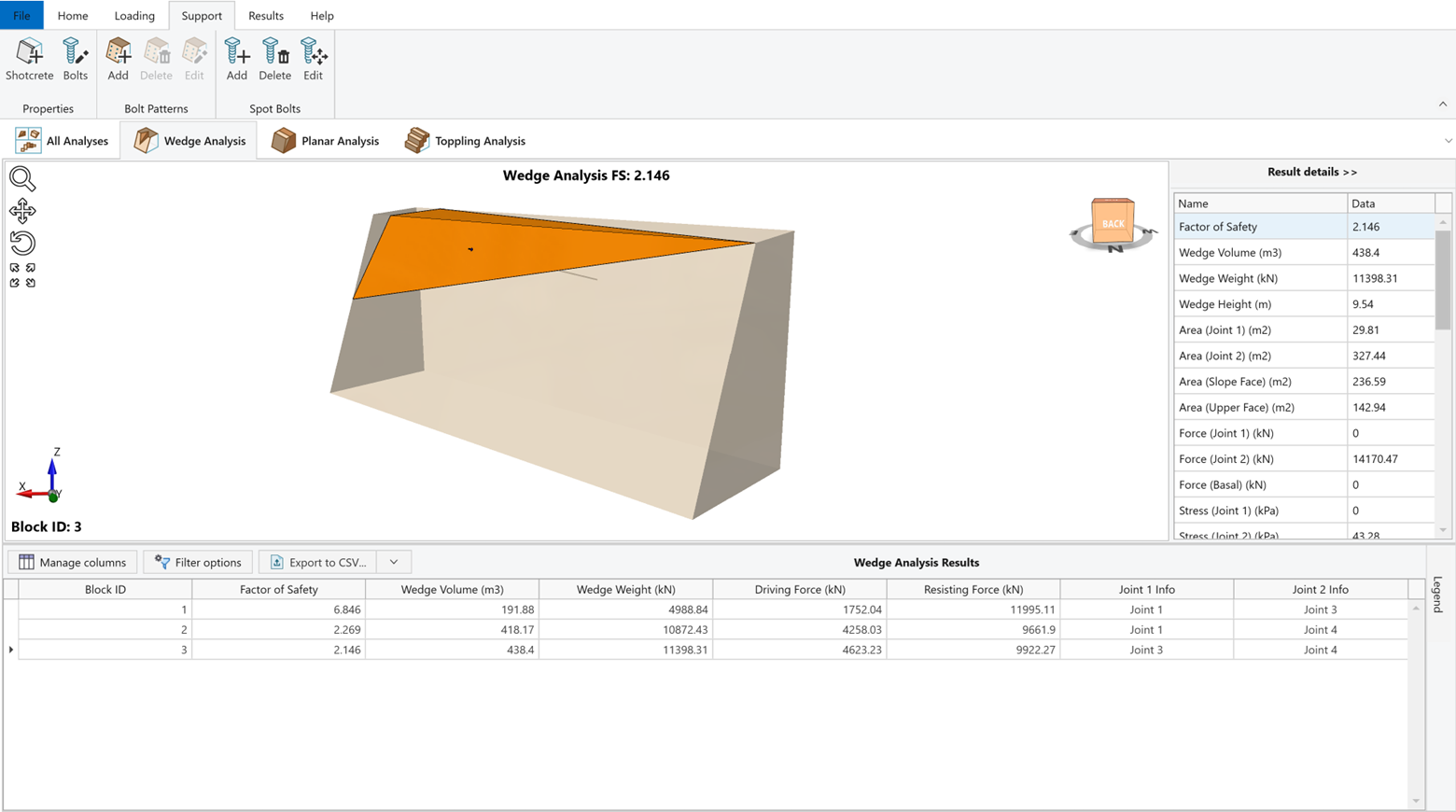
- First double click on Wedge Analysis pane to display 3D Wedge View.
- Click the Result Details button on the right side of the pane to maximize the sidebar.
- Double click on Block ID = 3 to select the block.
Note that the Area (Slope Face) (m2) = 236.59. This is the area of the wedge face on the slope. If we multiply this area by Pressure = 30 kPa from applied pressure support in previous chapter, we obtain a force of about 7097.7 kN. Therefore, if we add a single, simple force bolt with Force (kN) = 7097.7, we should get the same Factor of Safety = 2.146 with pressure support.
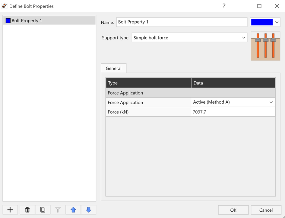
- Now select Support > Properties > Bolts again.
- Select Bolt Property 1.
- Set Support Type = Simple Bolt Force.
- Set Force Application = Active.
- Set Force = 7097.7 kN as calculated.
- Click OK to apply changes and close the dialog.
- Select Support> Spot Bolts > Add

- Mouse over and click on the wedge on the slope face.
- The Add Spot Bolt dialog opens, allowing you to modify the geometry and set up properties for the bolt.
- Set Orientation = Trend & Plunge and enter following values:
- Trend = 225
- Plunge = 15
- Trend = 225
- Set Bolt Length = 20.
- Set Bolt Property = Bolt Property 1.
- Click OK to apply the changes and close the dialog.
Notice that the defined spot bolt is applied, and Factor of Safety increased to 2.146 for Block ID = 3 in Wedge Analysis. This is exactly the same value obtained with applying pressure support. Note that, in both cases, support Model was set to Active.
Finally, we'll demonstrate that an External Point Load of 7097.7 kN, applied with same orientation as Spot Bolt and Pressure Load (Trend/Plunge = 225/15) will also give us a Factor of Safety of 2.146.
Before continuing, ensure that spot bolt is deleted from the model following instructions in the sections above.
- Select Loading > Define Loads > Point

- Click Add Single Row

- Enter the following values:
- Trend = 225
- Plunge = 15
- Force Magnitude = 7097.7 kN
- Apply To = Slope
- Trend = 225
- Keep Height Below Crest = 0.
- Click OK to apply the changes and close the dialog.
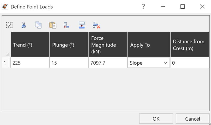
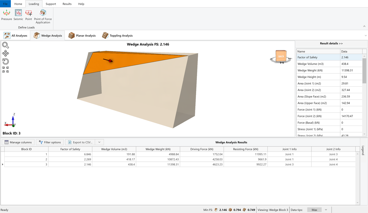
Notice that the defined External Point Load is applied, and Factor of Safety increased to 2.146 for Block ID=3 in Wedge Analysis. This is again exactly the same value obtained by applying Spot Bolt and Pressure Support.
- Before continuing, ensure that External Point Load is deleted from the model by deleting the load in Define Point Load dialog.
- To restore the split-screen view in RocSlope2, double-click on anywhere off the model in the 3D Wedge View or click on All Analyses icon.
7.0 Seismic Load
Before we conclude the tutorial, we will demonstrate how to include Seismic Load in the analysis.
- Select Loading > Define Loads > Seismic

- Set Direction = Slope direction / vertical coefficient.
- Set Horizontal Coefficient = 0.1.
- Keep Vertical Coefficient = 0.
- Click OK to apply the changes and close the dialog.
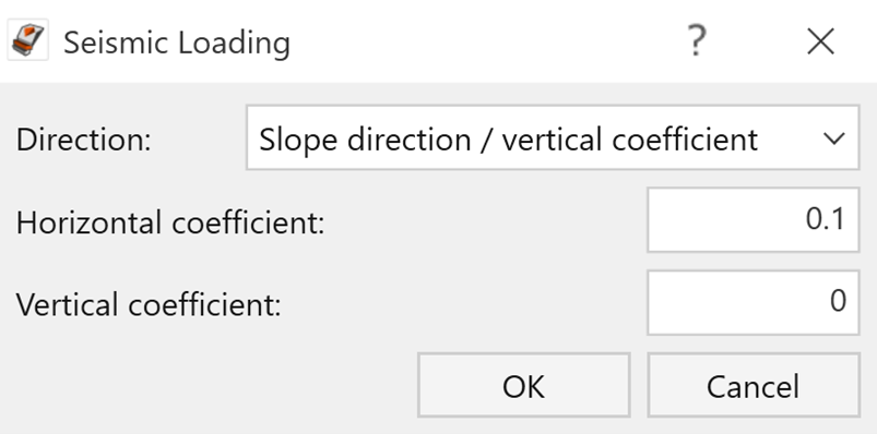
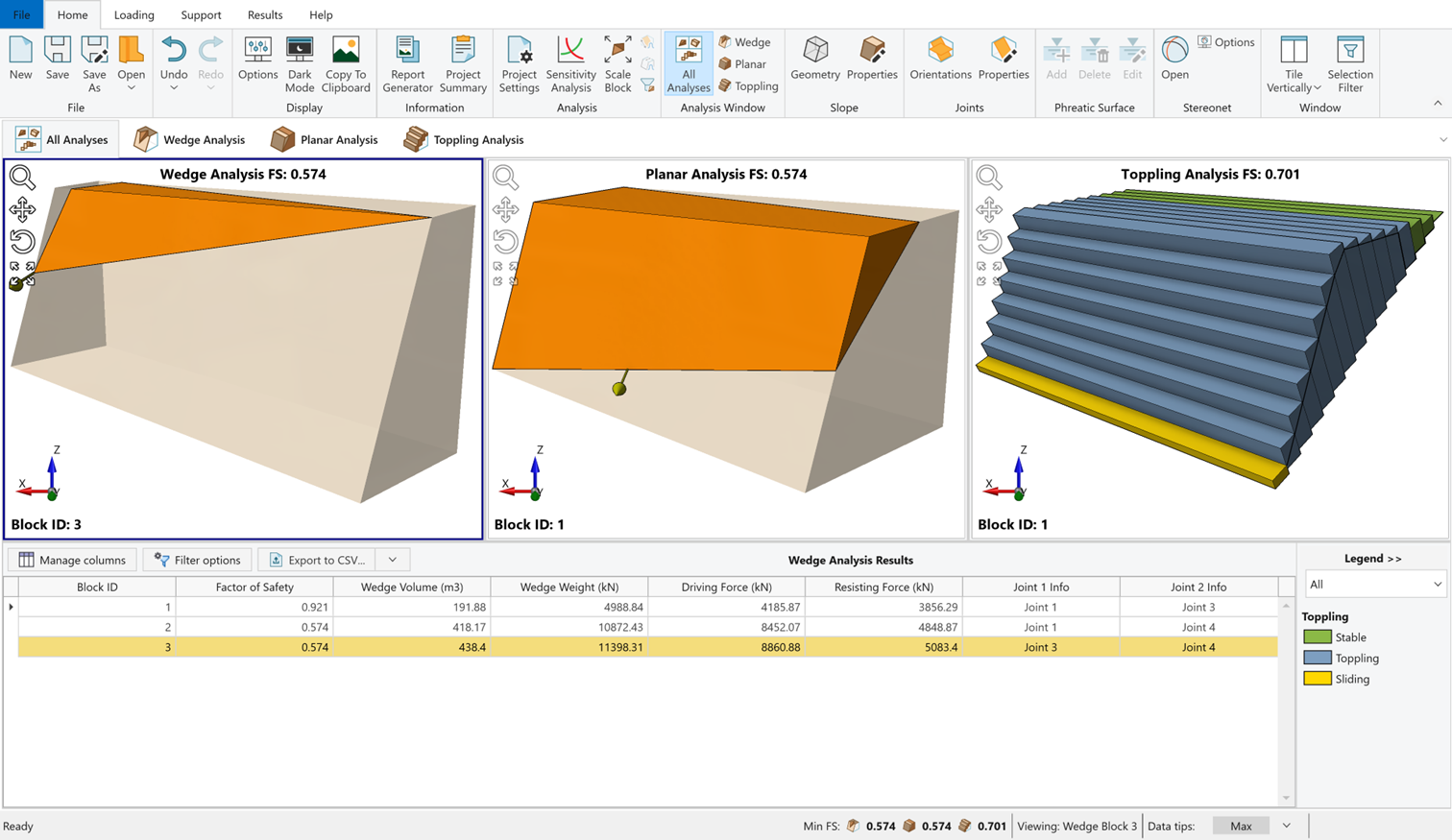
An arrow representing the Seismic Force is now displayed on the model for each analysis. The Seismic Force applied to a block is F = 0.1 * g * m, where g = gravitational acceleration and m = mass of the wedge.
Notice that the lowest Factor of Safety now decreased to 0.574 for Wedge Analysis, 0.574 for Planar Analysis and 0.701 for Toppling Analysis.
This concludes the tutorial. You are now ready to proceed to the next tutorial, Tutorial 5 – Sensitivity & Probabilistic Analysis.