7 - Bench Profile with Loading
1.0 Introduction
Evaluating and managing slope stability is a critical aspect of bench design. It involves conducting slope stability analyses, considering factors such as slope angles, rock mass properties, and potential failure mechanisms such as wedge and planar sliding due to the presence of geological features such as faults and joints. In this example, we will be accounting for loading on top of the benches from overburden and waste material.
Finished Product
The finished product of this tutorial can be found in the Tutorial 07 Bench Profile with Loading folder. All tutorial files installed with RocSlope3 can be accessed by selecting File > Recent Folders > Tutorials Folder from the RocSlope3 main menu.
2.0 Opening the Starting File
- Select File > Recent > Tutorials Folder.
- Go to the Tutorial 07 Bench Profile with Loading
folder, and open the file Tutorial 07 Bench Profile with Loading - starting file.rocslope_model.
This model already has the following defined and provides a good starting point to start computing blocks:
- Project Settings
- External Geometry
- Material Properties
- Measured Joints
- Joint Properties
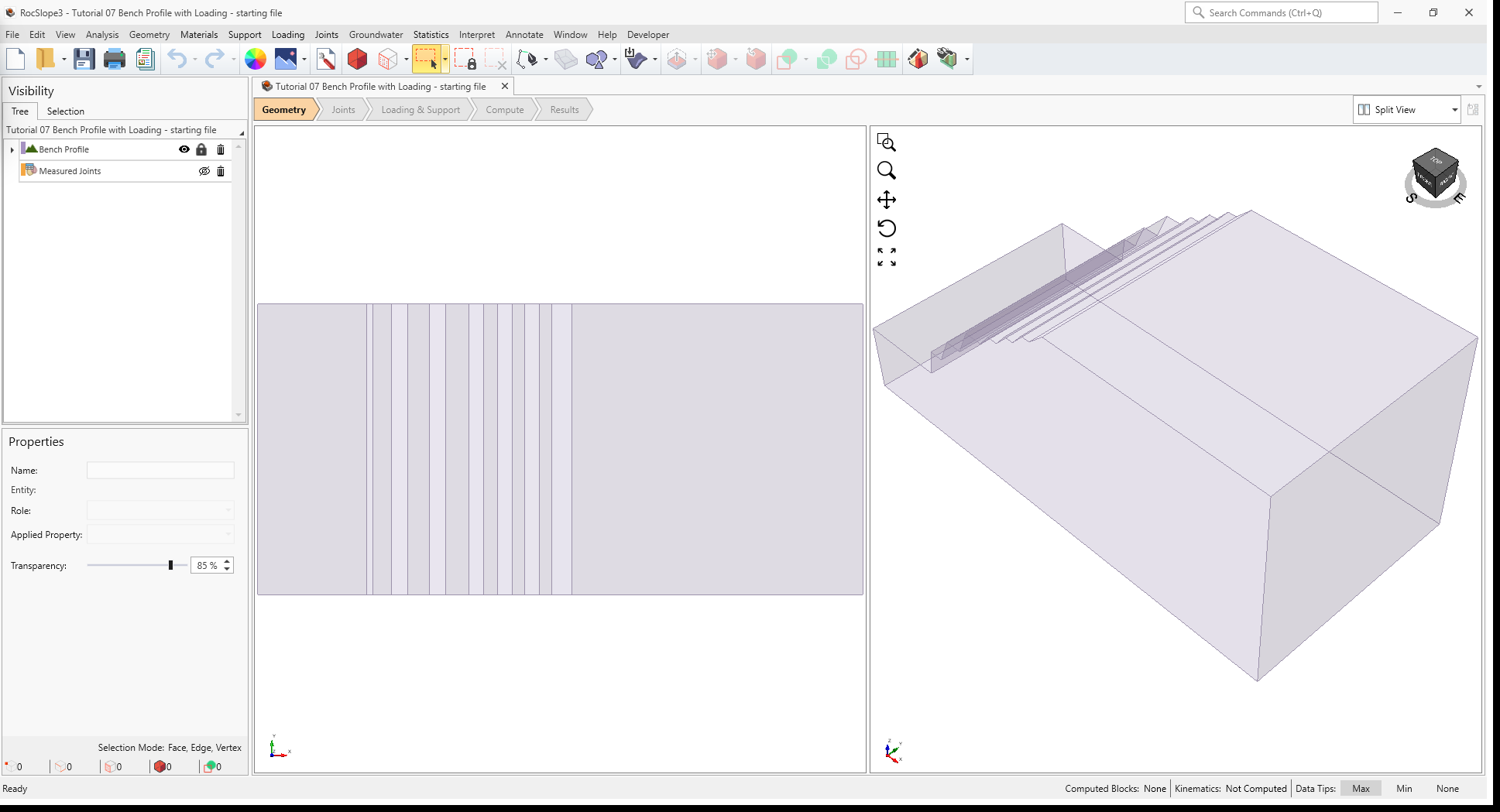
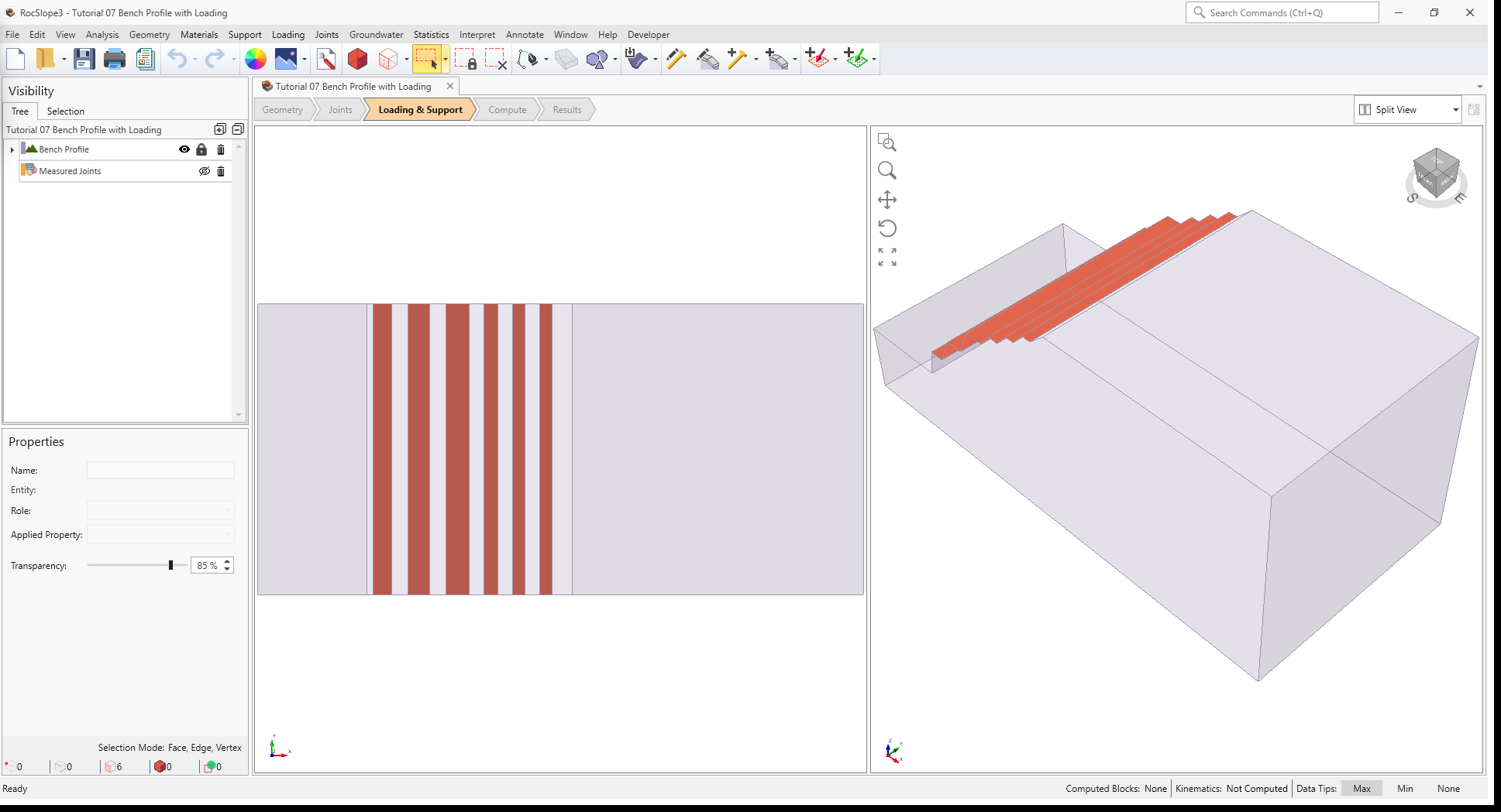
In the starting model, the external is defined by an extruded profile of seven benches, dipping in toward the west at a dip direction of 270 degrees.
2.1 Project Settings
Review the Project Settings.
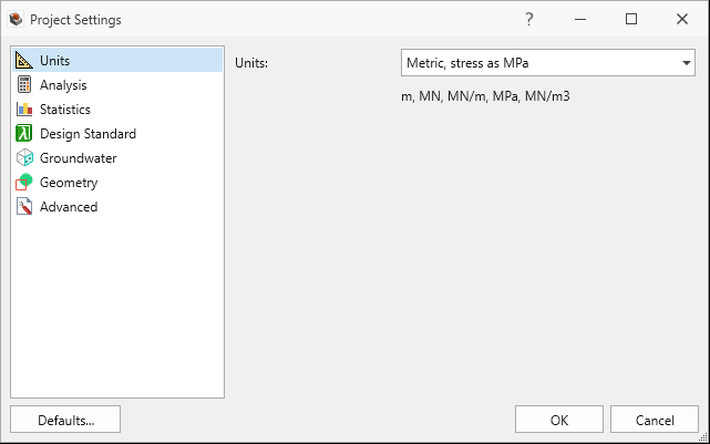
- Select Analysis > Project Settings

- Select the Units tab. Ensure Units are Metric, stress as
MPa.
Units tab in Project Settings dialog - Select the Analysis tab.
- Ensure Design Factor of Safety = 1.2.
- Ensure Successive Failure is ON.
- Ensure Combined blocks is OFF. We will only be analyzing unit blocks in this tutorial.

Analysis tab in Project Settings dialog
- Click Cancel to exit the dialog.
2.2 Material Properties
Review the Material Properties.
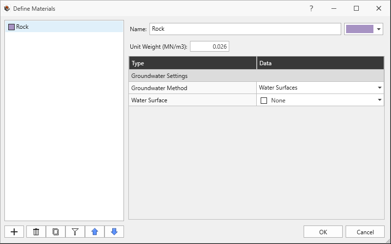
- Select Materials > Define Materials

- One (1) material property is defined in the Define Materials dialog. The Rock
material property has:
- Unit Weight = 0.026 MN/m3.
- No Water Surface applied.
Define Materials dialog
- Click Cancel to exit the dialog.
2.3 External Geometry
The External is of an inter-ramp profile with multiple benches and composed of one volume assigned with the Rock material property.
2.4 Joint Properties
Review the Joint Properties.
- Select Joints > Define Joint Properties
 . Two (2) joint properties are
defined.
. Two (2) joint properties are
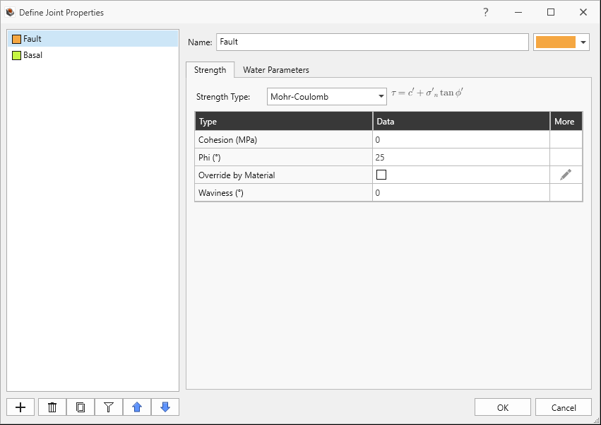
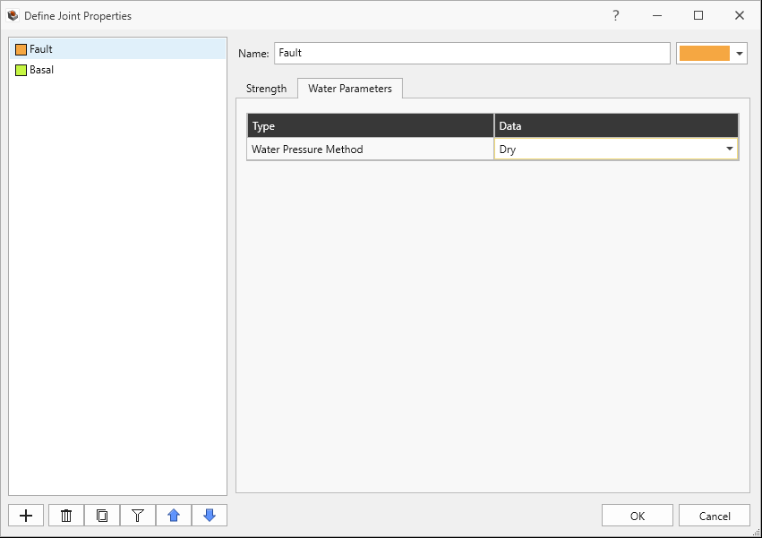
defined. - The Fault joint property has:
- Strength Type = Mohr-Coulomb
- Cohesion = 0 MPa
- Phi = 25 degrees
- Waviness = 0 degrees
Fault Joint Property Strength tab in Define Joint Properties dialog
- Water Pressure Method = Dry
Fault Joint Property Water Parameters tab in Define Joint Properties dialog
- The Basal joint property has:
- Strength Type = Mohr-Coulomb
- Cohesion = 0 MPa
- Phi = 10 degrees
- Waviness = 0 degrees
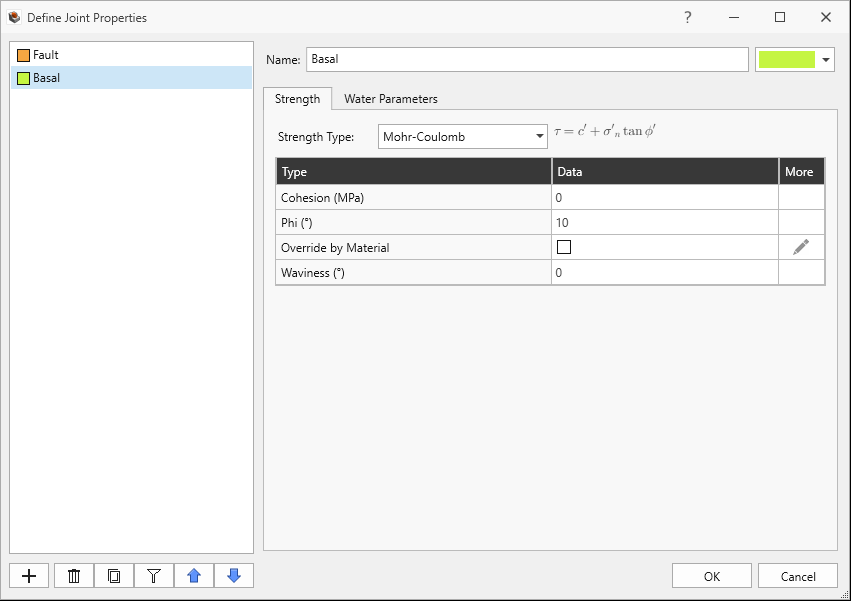
Basal Joint Property Strength tab in Define Joint Properties dialog
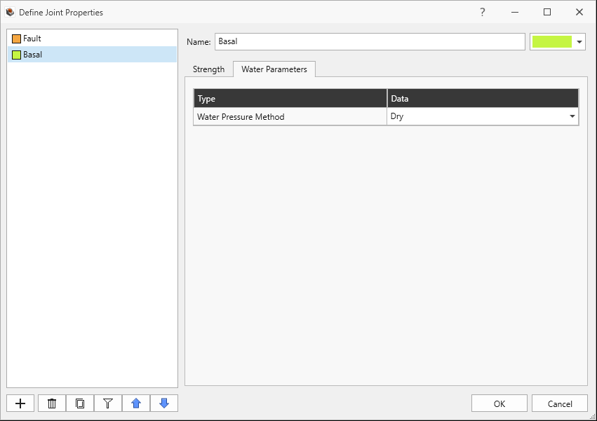
- Water Pressure Method = Dry
Basal Joint Property Water Parameters tab in Define Joint Properties dialog
- Click Cancel to exit the dialog.
2.5 Measured Joints
Review the Measured Joints.
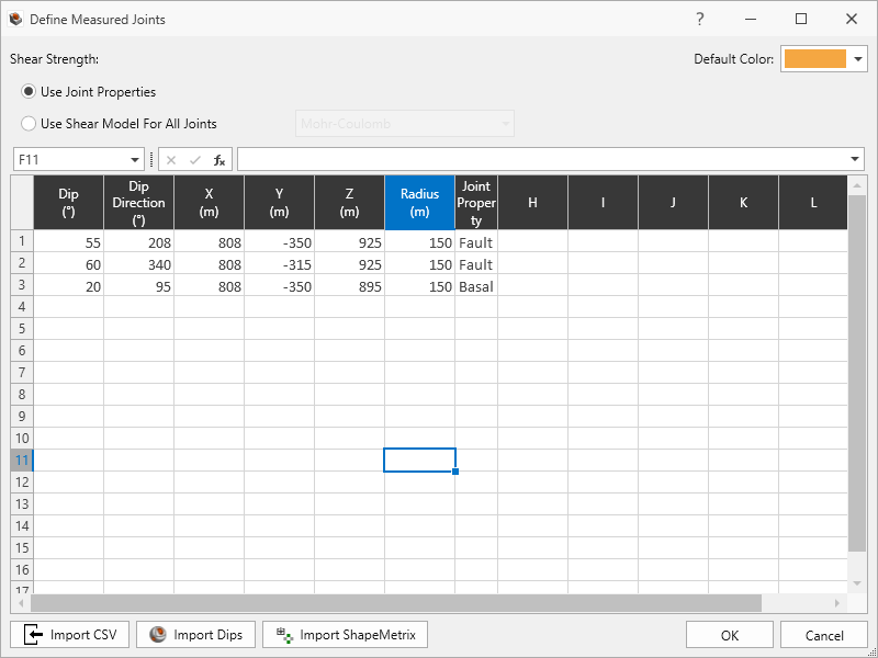
- Select Joints > Define Measured Joints
 . Three (3) Measured Joints are defined which persist the entire slope.
 - Click Cancel to exit the dialog.
Listed in order of Dip, Dip Direction, X, Y, Z, Radius, and Joint Property:
| Dip | Dip Direction | X | Y | Z | Radius | Joint Property |
|---|---|---|---|---|---|---|
| 55 | 208 | 808 | -350 | 925 | 150 | Fault |
| 60 | 340 | 808 | -315 | 925 | 150 | Fault |
| 20 | 95 | 808 | -350 | 895 | 150 | Basal |
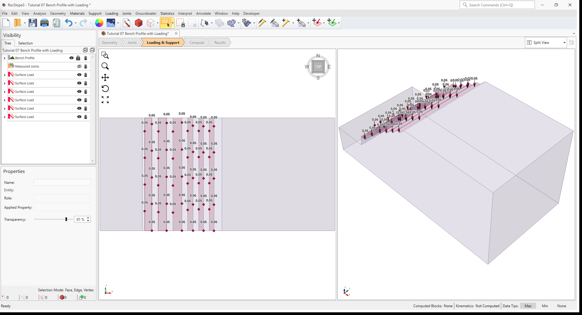
3.0 Loading
In this model, loading will be applied to each of the benches (except for the uppermost bench) as a constant downward uniformly distributed load.
To apply a load to selected faces:
- Navigate to the Loading & Support workflow tab

- Turn off the visibility of Measured Joints by clicking the Eye icon
 for the Measured Joints
node in the Visibility Tree.
for the Measured Joints
node in the Visibility Tree. - Select Edit > Selection Mode > Faces Selection
 . In this selection mode,
clicking on an entity will select the face(s) only.
. In this selection mode,
clicking on an entity will select the face(s) only. - Select the top bench faces (except for the uppermost bench) by holding CTRL and left-clicking on the faces.
- Select Loading > Add Loads to Selected

- In the Add Load to Selected dialog, enter the following:
- Name = Surface Load
- Load Type = Uniform Load
- Magnitude = 0.05 MN/m2
- Orientation = Trend/Plunge
- Trend = 0 degrees
- Plunge = 90 degrees (i.e., vertically down)
- Click OK close the dialog and add the loads.
Six (6) Surface Load nodes are added to the Visibility Tree. The viewport shows the surface load direction arrows and magnitudes.
4.0 Compute
RocSlope3 has a two-part compute process.
4.1 Compute Blocks
The first step is to compute the unit blocks which may potentially be formed by the intersection of joints with other joints and the intersection of joints with the free surface.
To compute the unit blocks:
- Navigate to the Compute workflow tab

- Select Analysis > Compute Blocks

As compute is run, the progress bar reports the compute status. Once compute is finished, the Results
node is added to the Visibility Tree and All Valid Unit Blocks are blocks are
shown in the viewport. The Results node consists of the collection of valid unit blocks and the
socketed slope. The original External and Joint Surface visibility is turned off.
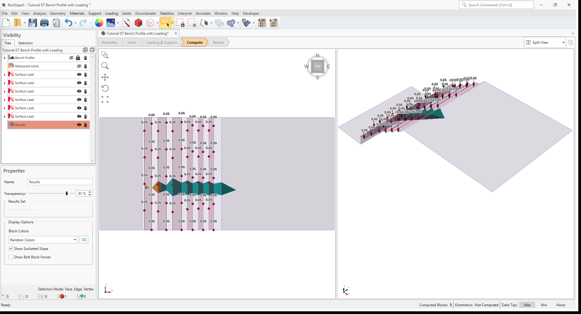
Once compute is finished, the blocks are coloured according to the Block Color option (Random Colors) set in the Results node's Property pane.
Compute Blocks only determines the geometry of the unit blocks. In order to obtain other information such as the factor of safety, Compute Kinematics needs to be run.
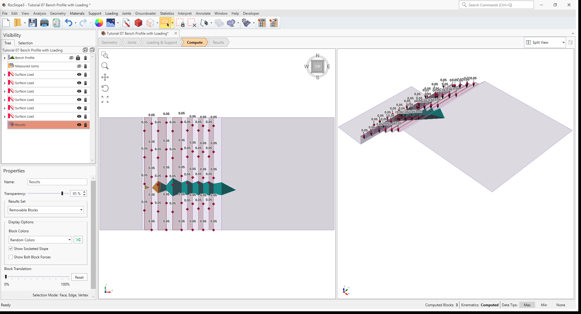
4.2 Compute Kinematics
The second and final compute step is to compute the removability, forces, and factor of safety for each of the valid unit blocks. If Combined blocks analysis is selected under Project Settings, then this step also computes removable combined blocks and their factor of safety.
To compute the block kinematics:
- Ensure that the Compute workflow tab is the active workflow.
- Select Analysis > Compute Kinematics

As compute is run, the progress bar reports the compute status. By default, after Compute Kinematics
is run, only Removable Unit Blocks are shown.
5.0 Interpreting Results
Once both blocks and kinematics are computed, all block results can be viewed in a grid format.
5.1 Block Information
To view all block results:
- Navigate to the Results workflow tab

- Select Interpret > Block Information

Visualizing blocks can be difficult when the slope extents are large compared to the block extents.
To zoom into all blocks:
- Select Interpret > Zoom To All Blocks

The Block Information pane shows the collection of blocks according to the Block Type and Results Set
settings. The Block Type and Results Set shown can be selected in the Results tab of the Display Options, or the Properties pane for the Results Node. In this case, only Removable Unit Blocks are colored and listed in Block Information.
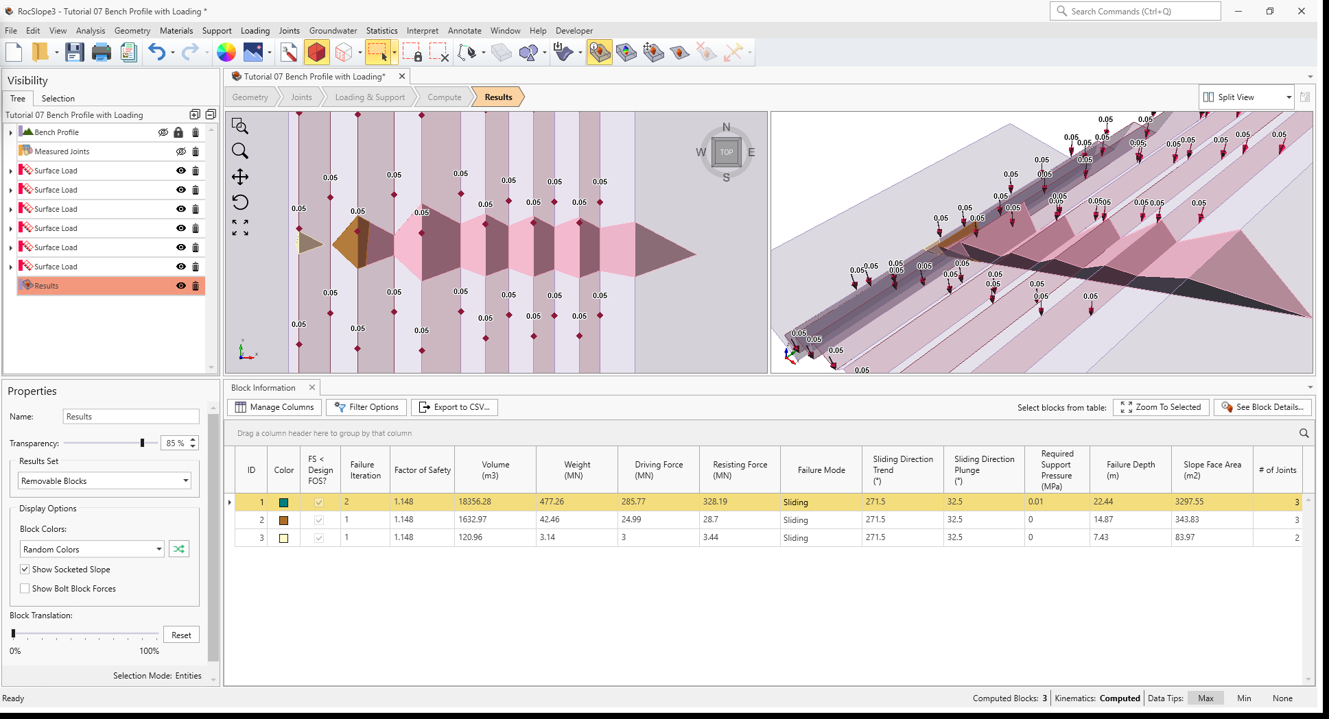
Three (3) valid unit blocks are formed and all of the unit blocks are Removable and have a Factor of Safety less than the Design Factor of Safety (< 1.2).
The smallest unit block at the lowest bench is failing at the crest and is not adjacent to any other blocks. The middle unit block right above it is also failing at the crest due to the presence of the basal plane to which acts as a release plane. Both unit blocks are immediately unstable and fail in Failure Iteration = 1. In other words, they are the key blocks. Note that the stability of the large uppermost unit block, spanning several bench levels, is controlled by the stability of the middle unit block and can only fail once the middle unit block has failed and detached from the slope. Therefore, it fails in Failure Iteration = 2.
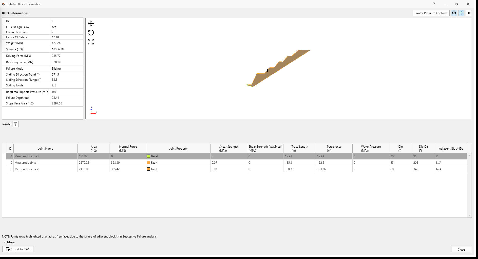
5.2 Detailed Block Information
To view more information about the large-scale unit block spanning multiple benches:
- Select Block ID 1 by clicking either a row in the Block Information pane or graphically in the viewport.
- Click See Block Details

- The Detailed Block Information window shows:
- 3D rendering of the block in isolation.
- General Block Information (as listed in the row of Block Information pane). Note the Sliding Direction and Sliding Joints. The presence of these structures control the mode of failure.
- Joints information. Note that the Basal joint is now a free surface once the middle block is removed. The block becomes unstable due to the loss of the (previously) supporting Basal joint plane and an increase in the degree of freedom for geometric removability and sliding direction.
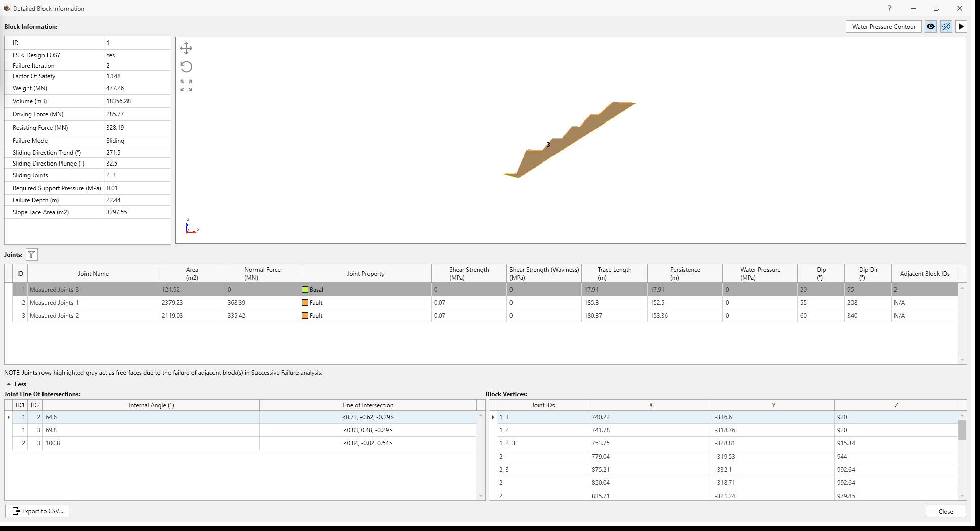
- Joint Line of Intersection and Block Vertices (select More to expand the information)
- Click Close to close the window.
6.0 Bench Design Extension
In order to mitigate the failure risk, given the presence of the controlling joint structures, the following could be considered:
- Stabilize key blocks. Adding supports to stabilize the key blocks will ensure the stability of the entire slope.
- Reduce the overall slope angle. Ensure that the overall slope angle, inter-ramp angles, and bench faces are less steep than the line of intersection between the Fault joints such that wedges cannot form.
- Cut back slope. Cut back benches until bench crests are behind the line of intersection between the Fault joints, such that wedges cannot form.
Crest failures on benches can be further analyzed in RocSlope2 using Bench Design features to determine the appropriate bench width and optimize on bench face angle, taking into consideration the back-break distance and spill width.
This concludes Tutorial 07.