Bolt Force Diagrams
A Bolt Force Diagram, as defined in RocTunnel3, represents the available tensile force which a bolt can apply to a block, at any point along the length of the bolt. That is, if a block plane intersects a bolt at a certain location along its length, what is the maximum tensile support force that the bolt can apply to the block. This assumes that the bolt is mobilized in pure tension.
- For Mechanically Anchored bolts, the Bolt Force Diagram is simply a horizontal line, since a constant support force will be applied, regardless of where a block plane intersects the bolt.
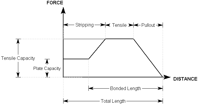
- For Grouted Dowel, Cable, Split Set or Swellex bolts, the Bolt Force diagram is determined by considering each possible tensile failure mode along the length of the support (Tensile, Pullout and Stripping, if applicable). The Failure Mode which generates the MINIMUM force determines the support force which can be generated, at each point along the support.
- For User-Defined Support, the Bolt Force Diagram is defined explicitly by the user, tensile properties (e.g. tensile strength, plate capacity, bond strength) are not entered.
For example, a possible Bolt Force Diagram for a grouted dowel, with a Bond Length less than 100%, and a plate capacity which is less than the tensile capacity, is illustrated below.

For more examples of typical Bolt Force Diagrams, see the following topics:
In addition to the Bolt Force Diagram, there are two other factors which ultimately determine the support force which can be supplied by a bolt in RocTunnel3: Bolt Orientation Efficiency and Shear Capacity. See these topics for more information.
If the bolt failure mode is Shear, the diagram will simply represent a constant (shear) support force for the length of the bolt.
For an overview of the bolt support implementation in RocTunnel3, see the Bolt Implementation topic. This discusses all of the parameters which affect the bolt support capacity and summarizes all possible cases.
Interpretation of Bolt Force Diagrams
The user should recognize that a Bolt Force Diagram implemented in
RocTunnel3 does not necessarily represent the true state of stress or
loading mobilized by a given bolt. The Bolt Force Diagram simply
represents the maximum available tensile force, which a given bolt can
theoretically apply to a block, at any point along its length. This is
based on the assumptions described for each bolt type in RocTunnel3.
Remember
that the RocTunnel3 analysis is a limit equilibrium analysis.
Displacements and strains are not considered in such an analysis. In
order to realistically model the interaction of support and excavation,
and to calculate actual strains and loading mobilized within the
support, more sophisticated numerical analysis methods are required,
such as finite element or finite difference methods.
The
modelling of support in RocTunnel3 is a simple but useful method, of
accounting for the effect of the support system on the block, in a limit
equilibrium analysis. It is not intended to model the effect of the
block on the support system, and the Bolt Force Diagrams should not be
interpreted in this way.
Display of Bolt Force Diagrams
The actual Bolt Force Diagrams determined by RocTunnel3 can be displayed directly on the bolts in the model, in the 3D CAD View. This is done through the Interpret menu or toolbar.
To show bolt force diagrams on the bolts:
- Navigate to the Results workflow tab

- Select: Interpret > Show Bolt Force Diagrams.
The Bolt Force Diagrams will be displayed directly on the bolts in the model.
Bolt Force Diagrams and Display Options
On the Bolt Force Diagrams, the different failure modes will be indicated by different colours:
- Pullout = GREEN
- Tensile = RED
- Compression = DARK BLUE
- Stripping = CYAN
- Shear = MAGENTA
- User-Defined = YELLOW
- Unknown = BLUE
A Legend will also be displayed, indicating the colour/failure mode correspondence.
The default colours for the various bolt failure modes can be modified in the Display Options dialog under the Bolt Forces tab.