3 - Add Joint Surface
1.0 Introduction
The shape, size and spatial distribution of joint structures may be defined as any arbitrary planar/surface geometry, or a collection of discrete planar surfaces; these can include faults, folding fractures, foliations, or Discrete Fracture Networks (DFNs). This tutorial covers the use of an imported cross-jointed Discrete Fracture Network (DFN) and Fault which will be used to model the joints in RocTunnel3. The DFN consists of bedding planes at a Dip/Dip Direction of 20/85 degrees and orthogonal cross-joints. The Fault has a Dip/Dip Direction of 60/135 degrees.
Finished Product
The finished product of this tutorial can be found in the Add Joint Surface.roctunnel_model file. All tutorial files installed with RocTunnel3 can be accessed by selecting File > Recent Folders > Tutorials Folder from the RocTunnel3 main menu.
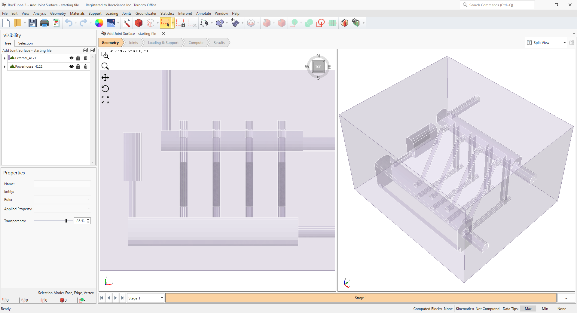
2.0 Opening the Starting File
- Select File > Recent > Tutorials Folder in the menu.
- In the Add Joint Surface folder, open the file Add Joint Surface - starting file.roctunnel_model.
This model already has the following defined and provides a good starting point to start defining joint surfaces:
- Project Settings
- Material Properties
- External Geometry
- Joint Properties
2.1 Project Settings
Review the Project Settings.
- Select Analysis > Project Settings

- Select the Units tab.
- Ensure Units are Metric, stress as MPa.
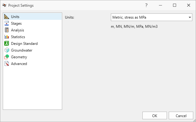
Units tab in Project Settings dialog - Select the Analysis tab.
- Ensure Design Factor of Safety = 1.
- Ensure Successive Failure = OFF. We will only be analyzing the blocks which daylight and are readily removable.
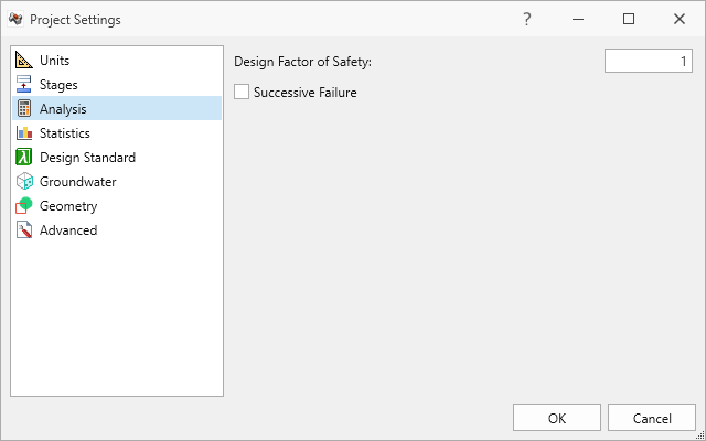
Analysis tab in Project Settings dialog - Click Cancel to close the dialog.
2.2 Material Properties
Review the Material Properties.
- Select Materials > Define Materials

- One (1) material property is defined. The Rock material property has:
- Unit Weight = 0.026 MN/m3.
- No Water Surface
applied.
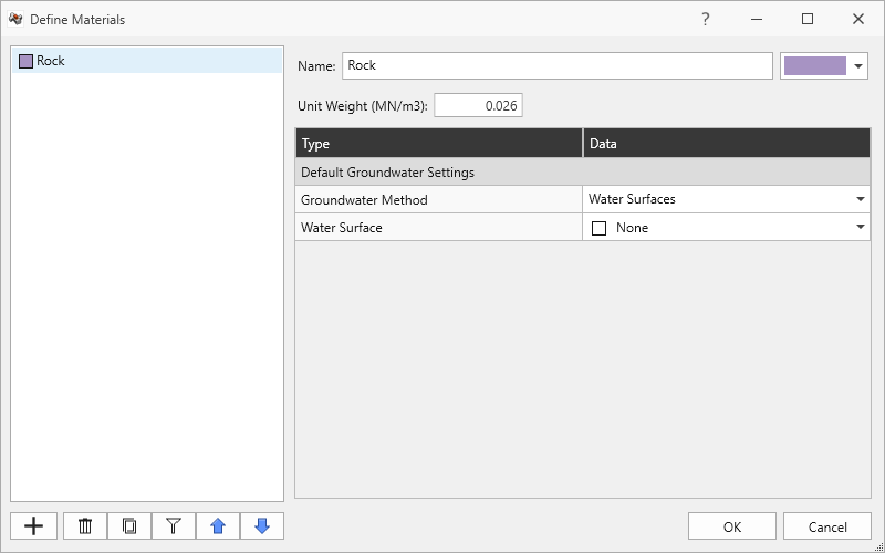
Rock material property in Define Materials dialog - Click Cancel to exit the dialog.
2.3 External Geometry
The External consists of an excavated Powerhouse structure assigned with No Material, bounded by an External box assigned with Rock material property.
3.0 Joint Properties
Review the Joint Properties.
- Select Joints > Define Joint Properties

- Two (2) joint properties are defined. The DFN joint property has:
- Strength Type = Barton Bandis
- JRC = 10
- JCS = 90 MPa
- Phir = 25 degrees
- Override by Material = OFF
- Waviness = 0 degrees
- Water Pressure Method = Dry.
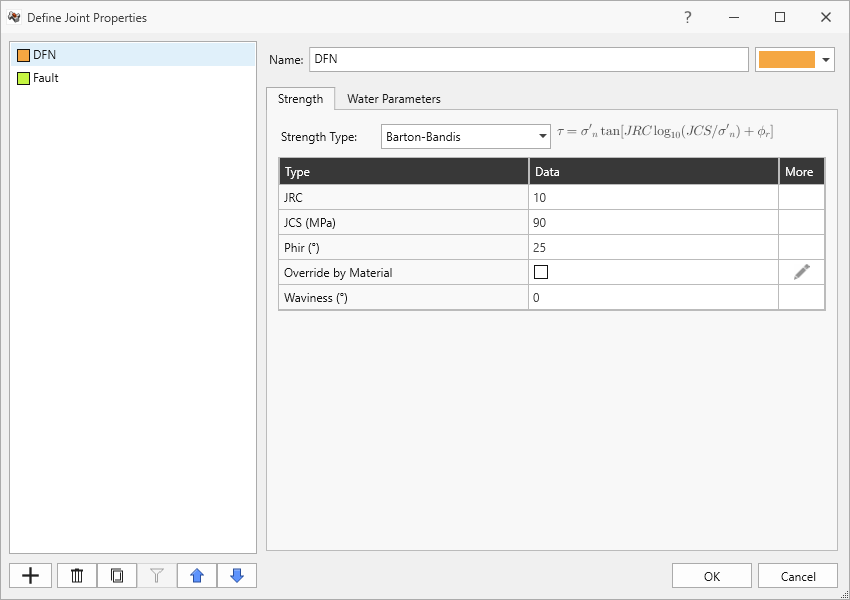
DFN joint property in Define Joint Properties dialog - The Fault joint property has:
- Strength Type = Mohr-Coulomb
- Cohesion = 0 MPa
- Friction Angle = 35 degrees
- Override by Material = OFF
- Waviness = 0 degrees
- Water Pressure Method = Dry.
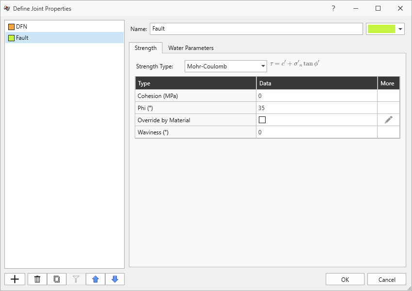
Fault joint property in Define Joint Properties dialog - Click Cancel to exit the dialog.
4.0 Add Joint Surface
In this example, we will be defining joint surfaces from a DFN geometry file. To import the DFN geometry:
- Select File > Import > Import Geometry
 . Several geometry file formats are supported. See the Import Geometry topic for more information.
 - In the Open dialog, select the Fault.rsgeomobj and DFN Cross-Jointed.rsgeomobj files from the Tutorials > Add Joint Surface folder and click Open.
- The Import Geometry dialog shows the file(s) and mesh entities available for import and a preview of the entity.
- Select All Geometry.
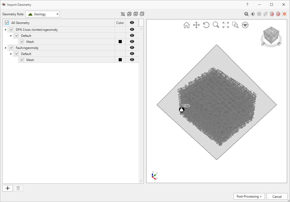
Import Geometry dialog - Click Post-Processing.
- Click Done to import the geometries.
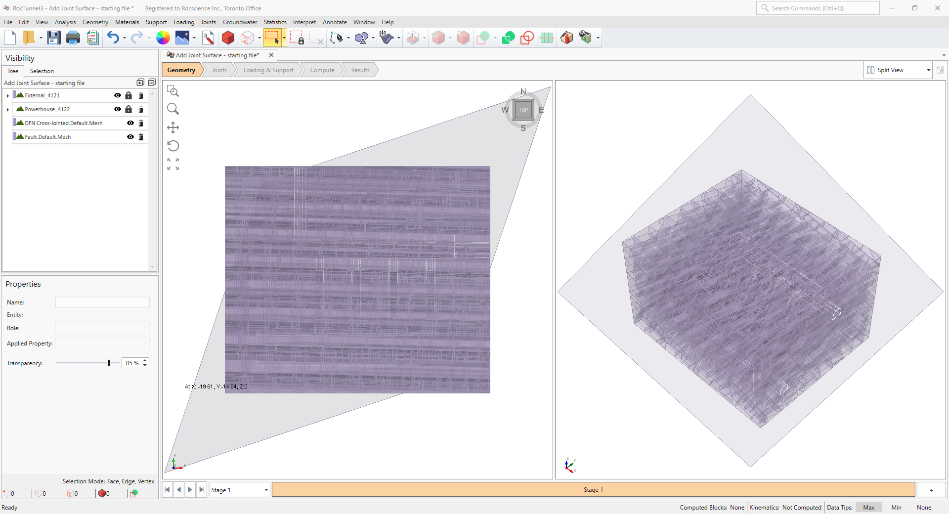
The geometries are imported into RocTunnel3 and are shown in the Visibility Tree.
4.1 Add Joint Surface
In order for RocTunnel3 to treat the imported surfaces as joints, they must be assigned as a joint surface using the Add Joint Surface option.
- Navigate to the Joints workflow tab

- Select the Fault.Default.Mesh node from the Visibility Tree
- Select Joints > Add Joint Surface

- In the Add Joint Surface dialog, enter:
- Joint Property = Fault.
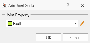
Add Joint Surface dialog - Click OK to set the entity as a Joint Surface.
- Select the DFN Cross-Jointed.Default.Mesh node from the Visibility Tree.
- Select Joints > Add Joint Surface
- In the Add Joint Surface dialog, enter:
- Joint Property = DFN. Each face of the entity is treated as a separate joint by RocTunnel3, all with the assigned Joint Property.
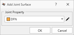
Add Joint Surface dialog - Click OK to set the entity as a Joint Surface.
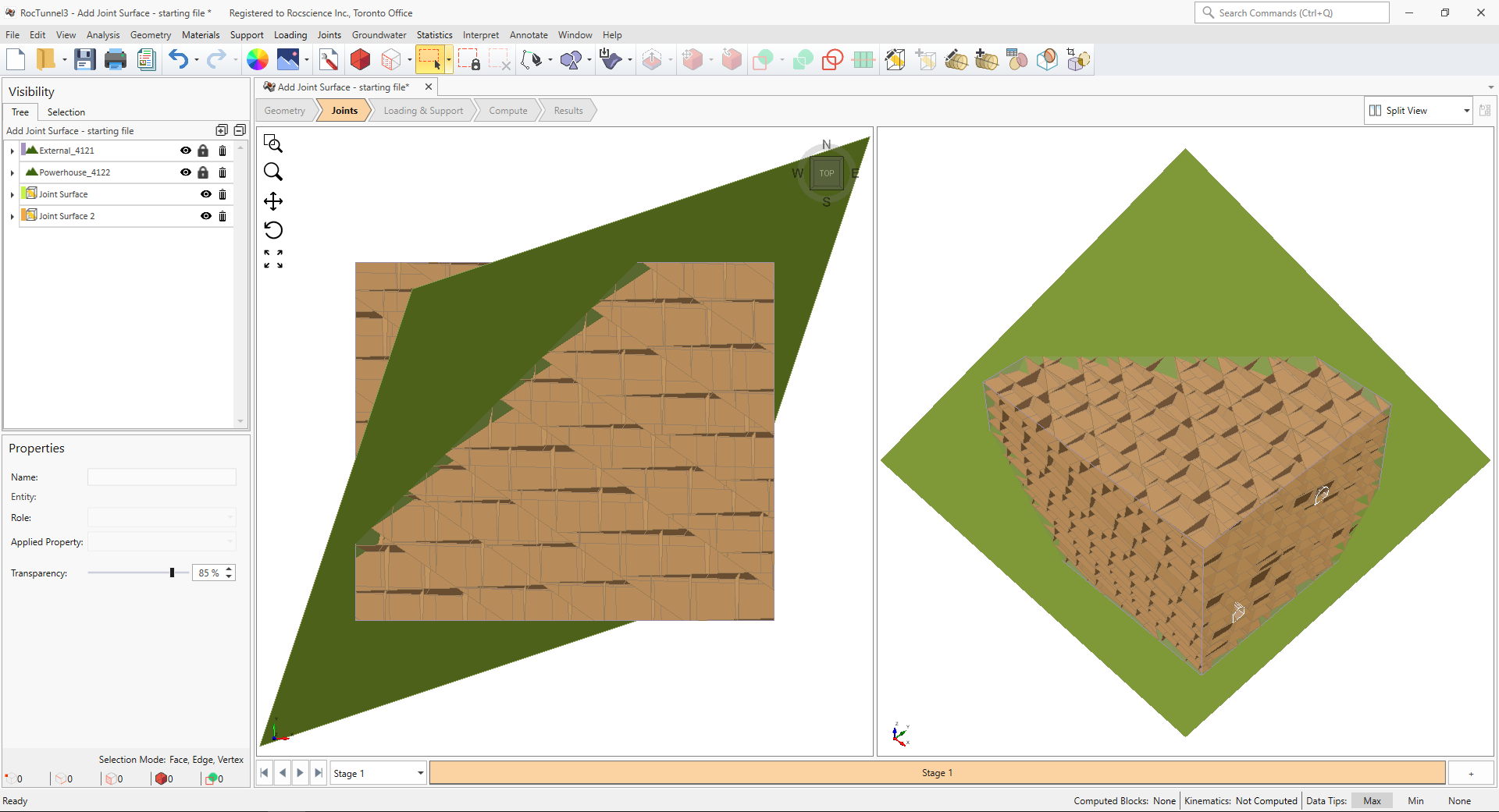
The joints are drawn in the 3D View.
5.0 Compute
RocTunnel3 has a two-part compute process.
5.1 Compute Blocks
The first step is to compute the blocks which may potentially be formed by the intersection of joints with other joints and the intersection of joints with the free surface.
To compute the blocks:
- Navigate to the Compute workflow tab

- Select Analysis > Compute Blocks

As compute is run, the progress bar reports the compute status. Once compute is finished, the Results node is added to the Visibility Tree and All Valid Blocks are blocks are shown in the 3D View. The Results node consists of the collection of valid blocks and the socketed excavation. The original External and Joint Surface visibility is turned off.
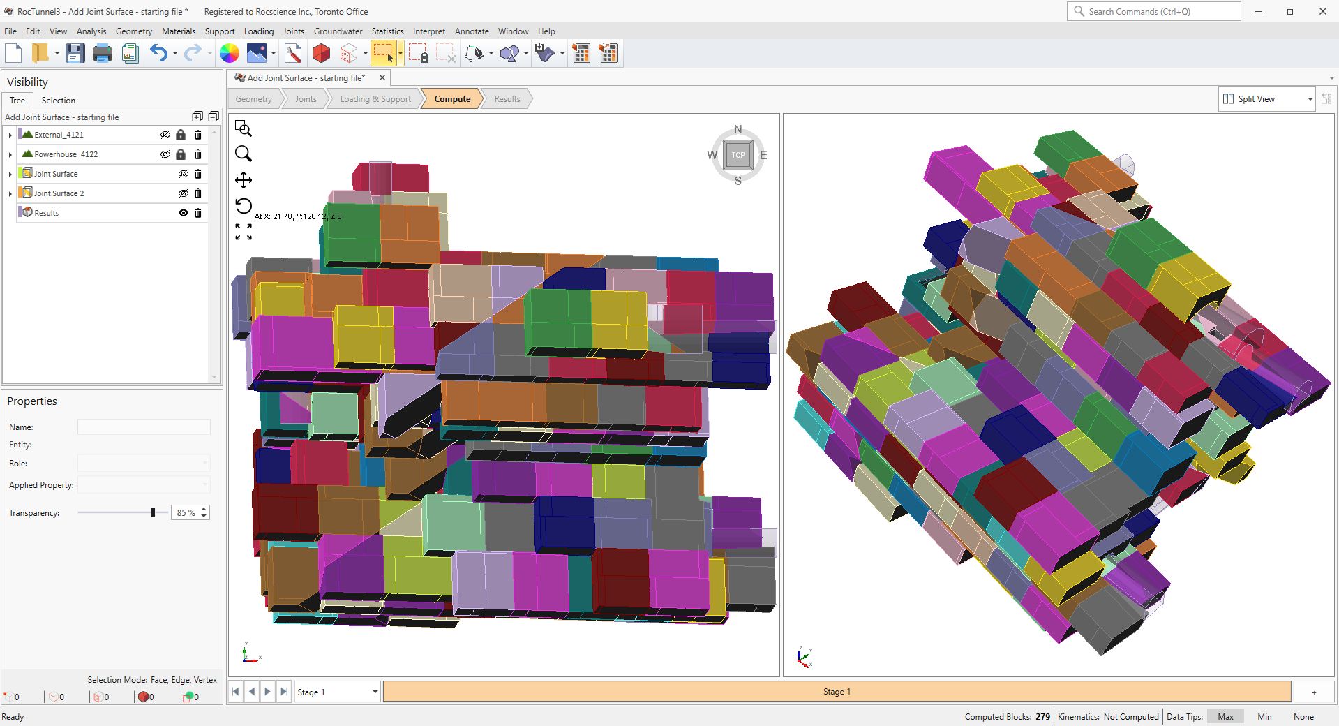
The blocks are coloured according to the Block Color option (Random Colors) set in the Results node's Properties pane.
Compute Blocks only determines the geometry of the blocks. In order to obtain other information such as the factor of safety, Compute Kinematics needs to be run.
5.2 Compute Kinematics
The second and final compute step is to compute the removability, forces, and factor of safety for each of the valid blocks.
To compute the block kinematics:
- Ensure that the Compute workflow tab is the active workflow.
- Select Analysis > Compute Kinematics

As compute is run, the progress bar reports the compute status. By default, after Compute Kinematics is run, only Removable Blocks are shown.
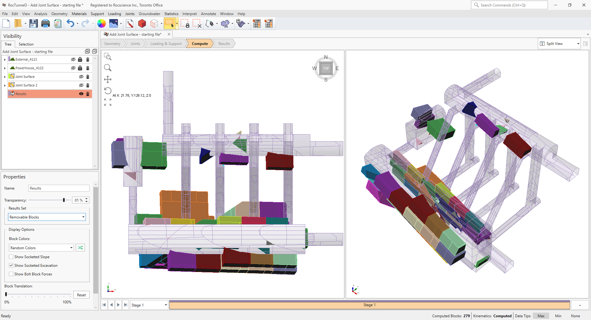
6.0 Interpreting Results
Once both blocks and kinematics are computed, all block results can be viewed in the Results workflow tab.
6.1 Failed Blocks
To view failed blocks:
- Select the Results node from the Visibility Tree
- Set Results Set = Failed (FS < Design FS)
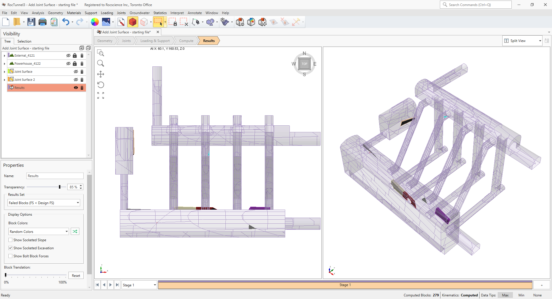
Even though many valid blocks are formed and are removable, only few of them are flagged as failed blocks with Factor of Safety less than the Design Factor of Safety of 1. The failed blocks slide along the steeply inclined joint faces on which the shear strength does not provide sufficient resistance.
This concludes Tutorial 3.