5 - Staged Excavation
1.0 Introduction
This tutorial introduces the concept of staging in which volumes can be excavated sequentially and then optionally backfilled after. At each stage of the excavation, new rock faces are exposed which could lead to new instabilities. This tutorial uses a simple extruded 30 m-long tunnel with a 5.5 m by 5.5 m drive, oriented at Trend/Plunge of 0/45 degrees. In each stage, a 10 m-long length of tunnel is excavated and in the final stage, all the previously excavated volumes are backfilled.
Finished Product
The finished product of this tutorial can be found in the Staged Excavation.roctunnel_model file. All tutorial files installed with RocTunnel3 can be accessed by selecting File > Recent Folders > Tutorials Folder from the RocTunnel3 main menu.
2.0 Opening the Starting File
- Select File > Recent > Tutorials Folder in the menu.
- In the Staged Excavation folder, open the file Staged Excavation - starting file.roctunnel_model.
This model already has the following defined and provides a good starting point to start defining stages:
- Material Properties
- External Geometry
- Joint Properties
- Measured Joints
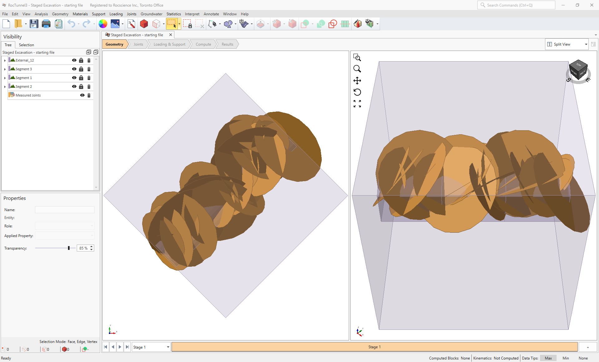
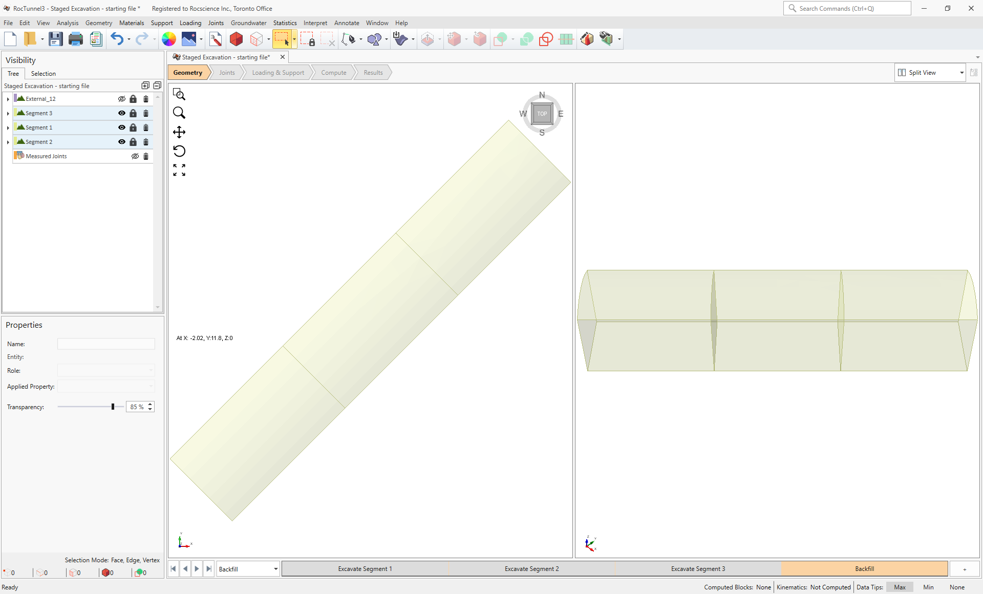
TIP: To visualize the tunnel geometry better, turn off the visibility of the Measured Joints and External_12 nodes in the Visibility Tree.
2.1 Project Settings
Our first step is to configure the analysis parameters for the model in Project Settings.
- Select Analysis > Project Settings

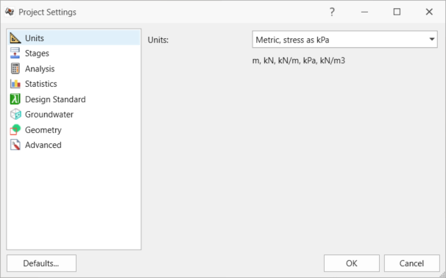
- Select the Units tab.
- Ensure Units = Metric, stress as kPa.
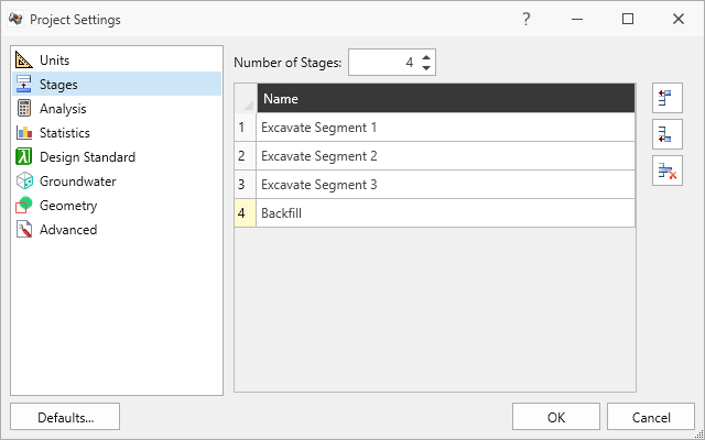
Units tab in Project Settings dialog - Select the Stages tab. By default, projects have only one stage.
- Set Number of Stages = 4. You should see Stage 1, Stage 2, Stage 3, and Stage 4 in the table.
- Rename Stage 1 to Excavate Segment 1
- Rename Stage 2 to Excavate Segment 2
- Rename Stage 2 to Excavate Segment 3
- Rename Stage 4 to Backfill
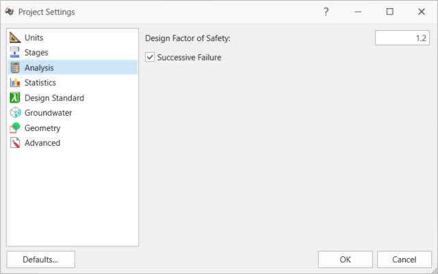
- Select the Analysis tab.
- Ensure Design Factor of Safety = 1.2.
- Ensure Successive Failure = ON. It is important in support design to identify key blocks and furthest possible extent of instabilities for strategic bolt placement and bolt length selection.
Analysis tab in Project Settings dialog - Click OK to close the dialog.
2.2 Material Properties
Review the Material Properties.
- Select Materials > Define Materials

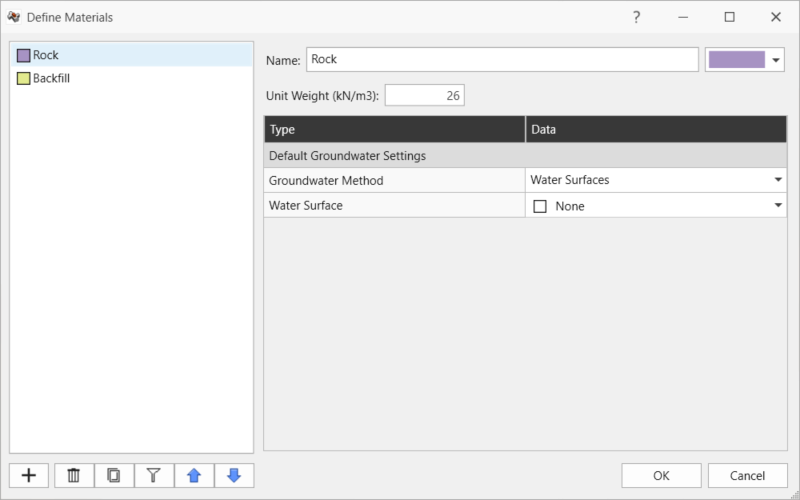
- Two (2) material properties are defined.
The Rock material property has: - Unit Weight = 26 kN/m3.
- No Water Surface applied.
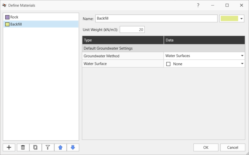
Rock material property in Define Materials dialog - The Backfill material property has:
- Unit Weight = 20 kN/m3.
- No Water Surface applied.
Backfill material property in Define Materials dialog - Click Cancel to exit the dialog.
2.3 External Geometry
The External consists of volume pieces assigned with the Rock material property. The Segment 1, Segment 2, and Segment 3 External pieces represent the volume regions of the planned staged excavations.
2.4 Joint Properties
Review the Joint Properties.
- Select Joints > Define Joint Properties

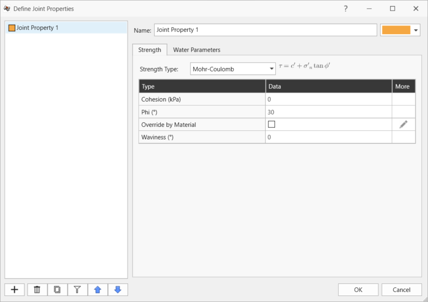
- One (1) joint property is defined. The Joint Property 1 joint property has:
- Strength Type = Mohr-Coulomb
- Cohesion = 0 kPa
- Friction Angle = 30 degrees
- Override by Material = OFF
- Waviness = 0 degrees
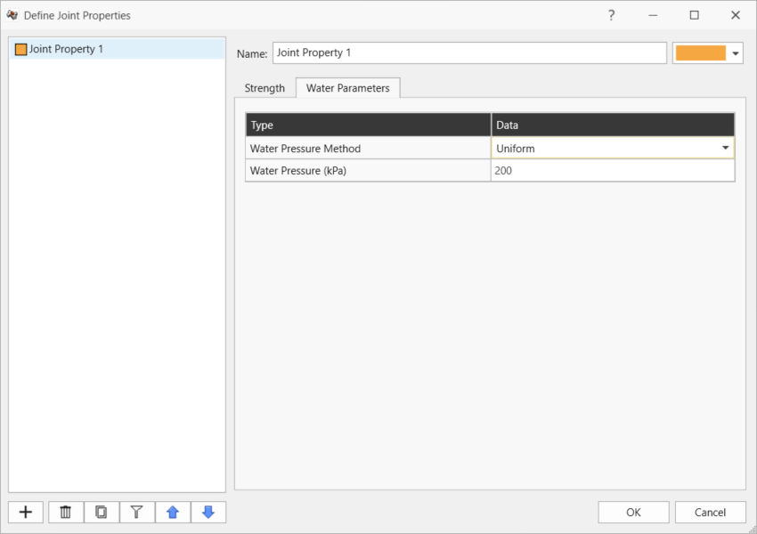
- Water Pressure Method = Uniform.
- Water Pressure = 200 kPa.
- Click Cancel to exit the dialog.
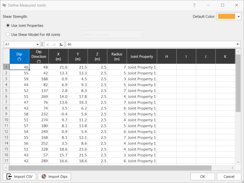
2.5 Measured Joints
Review the Measured Joints.
- Select Joints > Define Measured Joints

30 Measured Joints are defined and listed in order of Dip, Dip Direction, X, Y, Z, Radius, and Joint Property.
| Dip | Dip Direction | X | Y | Z | Radius | Joint Property |
| 46 | 48 | 21.6 | 21.5 | 2.5 | 7 | Joint Property 1 |
| 55 | 42 | 13.3 | 13.3 | 2.5 | 5 | Joint Property 1 |
| 59 | 188 | 0.9 | 4.5 | 2.5 | 3 | Joint Property 1 |
| 44 | 82 | 6.9 | 9.3 | 2.5 | 5 | Joint Property 1 |
| 52 | 137 | 2.8 | 8.3 | 2.5 | 7 | Joint Property 1 |
| 51 | 269 | 14 | 17.8 | 2.5 | 4 | Joint Property 1 |
| 47 | 76 | 13.6 | 19.3 | 2.5 | 7 | Joint Property 1 |
| 43 | 74 | 3.5 | 6.2 | 2.5 | 6 | Joint Property 1 |
| 58 | 232 | -0.4 | 5.6 | 2.5 | 5 | Joint Property 1 |
| 51 | 274 | 9.7 | 11.2 | 2.5 | 4 | Joint Property 1 |
| 57 | 180 | 8.1 | 13.8 | 2.5 | 5 | Joint Property 1 |
| 54 | 249 | 0.9 | 5.4 | 2.5 | 6 | Joint Property 1 |
| 55 | 168 | 8.1 | 12.1 | 2.5 | 7 | Joint Property 1 |
| 56 | 252 | 3.5 | 8.6 | 2.5 | 4 | Joint Property 1 |
| 51 | 228 | 18.6 | 23.6 | 2.5 | 4 | Joint Property 1 |
| 43 | 57 | 15.7 | 21.5 | 2.5 | 3 | Joint Property 1 |
| 42 | 289 | 16.6 | 18.6 | 2.5 | 6 | Joint Property 1 |
| 55 | 27 | 15.9 | 23.7 | 2.5 | 5 | Joint Property 1 |
| 54 | 212 | 19 | 23.9 | 2.5 | 3 | Joint Property 1 |
| 49 | 72 | 12.8 | 15.6 | 2.5 | 4 | Joint Property 1 |
| 41 | 175 | 9.2 | 10.2 | 2.5 | 7 | Joint Property 1 |
| 43 | 227 | 7.7 | 13.5 | 2.5 | 6 | Joint Property 1 |
| 56 | 280 | 15.7 | 22.8 | 2.5 | 3 | Joint Property 1 |
| 47 | 228 | 3.2 | 7.4 | 2.5 | 7 | Joint Property 1 |
| 56 | 282 | 12.5 | 14.3 | 2.5 | 5 | Joint Property 1 |
| 58 | 38 | 15.8 | 19.5 | 2.5 | 5 | Joint Property 1 |
| 53 | 151 | 14.3 | 19.9 | 2.5 | 7 | Joint Property 1 |
| 46 | 83 | 18.7 | 20.5 | 2.5 | 5 | Joint Property 1 |
| 52 | 54 | 13.7 | 15 | 2.5 | 4 | Joint Property 1 |
| 43 | 96 | 6.2 | 13 | 2.5 | 4 | Joint Property 1 |
- Click Cancel to exit the dialog.
3.0 Staged Excavations and Backfill
A different material property can be assigned to each External volume in each stage. Currently all External volumes are assigned with the Applied Property Rock.
3.1 Excavation
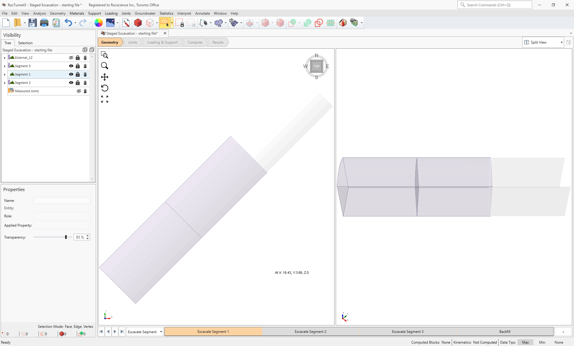
To excavate the Segment 1 volume in the Excavate Segment 1:
- Select External_12 and Measured Joints nodes and and click the Visibility
 button to turn off their visibility and be able to view the Segment 1, Segment 2, and Segment 3 External pieces better.
 - Select the Excavate Segment 1 stage from the Stage tabs at the bottom.
- Select the Segment 1 node from the Visibility Tree .
- In the Properties pane, set Applied Property = No Material. RocTunnel3 treats any External Geology volumes assigned "No Material" as excavated.
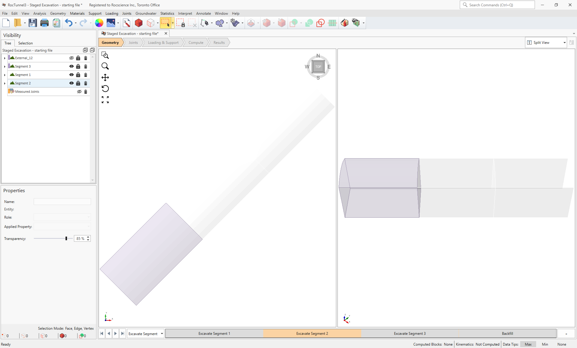
To excavate the Segment 2 volume in the Excavate Segment 2 stage:
- Select the Excavate Segment 2 stage from the Stage tabs at the bottom.
- Select the Segment 2 node from the Visibility Tree.
- In the Properties pane, set Applied Property = No Material.
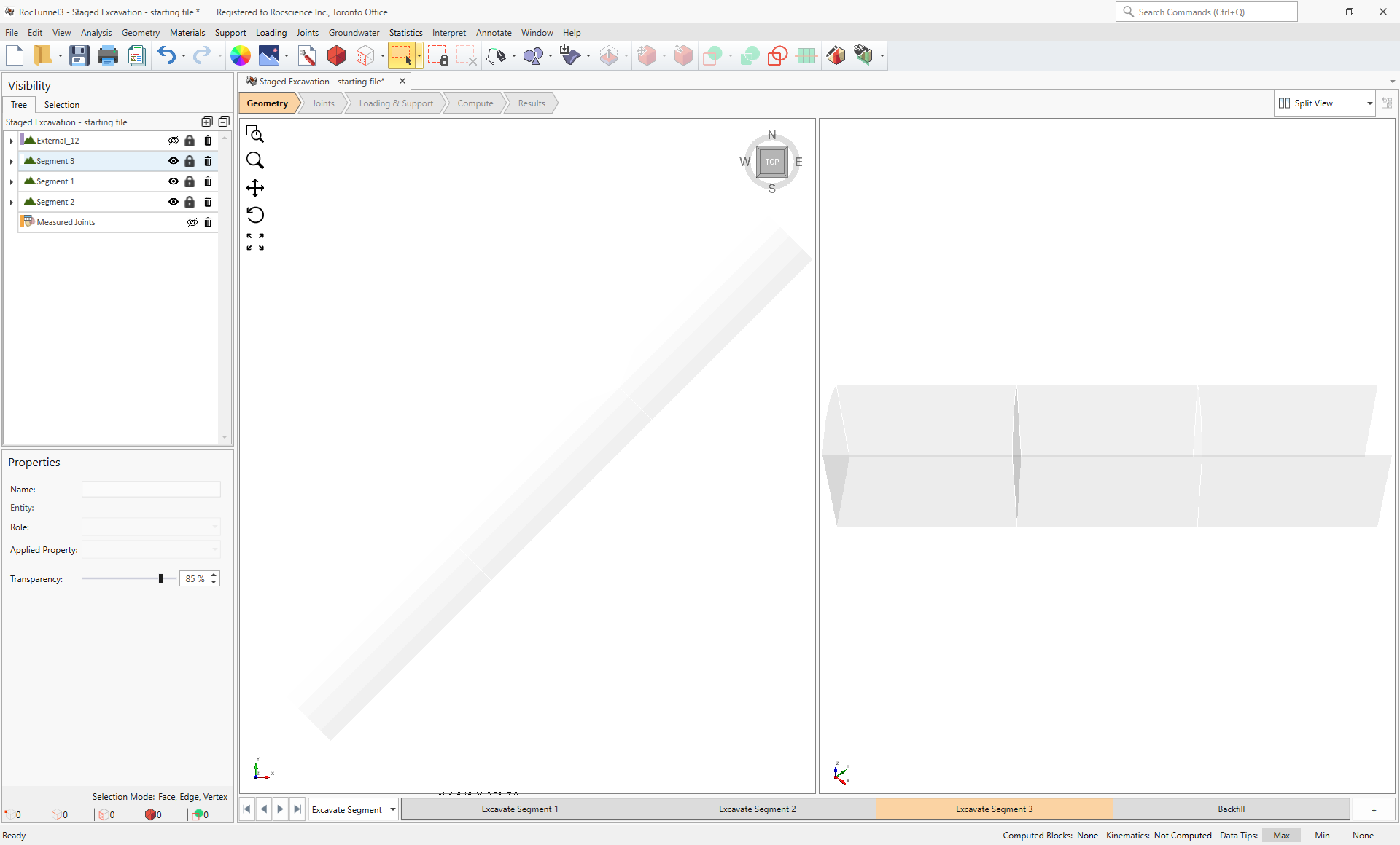
To excavate the Segment 3 volume in the Excavate Segment 3 stage:
- Select the Excavate Segment 3 stage from the Stage tabs at the bottom.
- Select the Segment 3 node from the Visibility Tree.
- In the Properties pane, set Applied Property = No Material.
3.2 Backfill
RocTunnel3 automatically treats External Geology volumes which have previously been excavated (i.e., assigned with Applied Property = No Material) in any stage and then assigned to a material property in a subsequent stage as "backfill". The key RocTunnel3 assumption to note for backfill volumes are:
- No blocks form within backfill volumes. Once a jointed rock mass is excavated, the joints are also removed with it and no longer exists when the void is backfilled.
- Blocks attached to backfill volumes are indefinitely stable and not considered valid for analysis. The backfill material is treated as a cement which "glues" adjacent blocks to it.
To backfill the Segment 1, Segment 2, and Segment 3 volumes in the Backfill stage:
- Select the Backfill stage from the Stage tabs at the bottom.
- Select the Segment 1, Segment 2, and Segment 3 nodes from the Visibility Tree.
- In the Properties pane, set Applied Property = Backfill.
To view the change in material assignment and excavation sequencing:
- Select the Excavate Segment 1 tab from the Stage Tabs at the bottom of the screen.
- Select the Excavate Segment 2 tab from the Stage Tabs at the bottom of the screen.
- Select the Excavate Segment 3 tab from the Stage Tabs at the bottom of the screen.
- Select the Segment 1 node from the Visibility Tree. Note that if you select any External Geology node, the colors in the Stage tabs indicate the Material Property assigned at each stage.
- Select the Segment 2 node from the Visibility Tree.
- Select the Segment 3 node from the Visibility Tree.
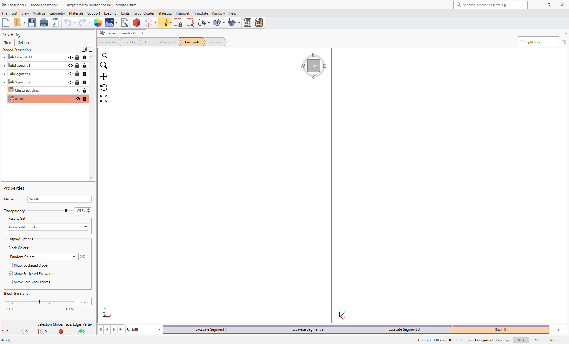
4.0 Compute
RocTunnel3 has a two-part compute process.
4.1 Compute Blocks
The first step is to compute the blocks which may potentially be formed by the intersection of joints with other joints and the intersection of joints with the free surface.
To compute the blocks:
- Navigate to the Compute workflow tab

- Select Analysis > Compute Blocks

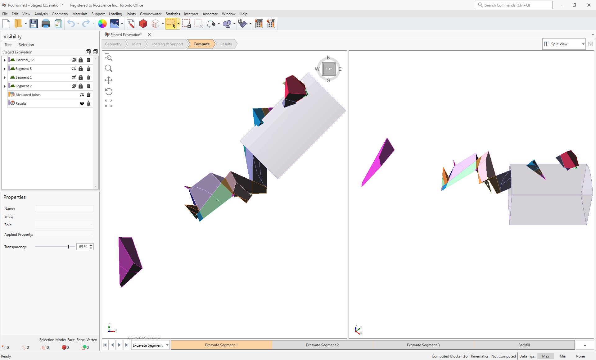
As compute is run, the progress bar reports the compute status. Once compute is finished, the Results node is added to the Visibility Tree and All Valid Blocks are blocks are shown in the 3D View. The Results node consists of the collection of valid blocks and the socketed excavation. The original External and Measured Joints visibility is turned off.
The blocks are coloured according to the Block Color option (Random Colors) set in the Results node's Properties pane.
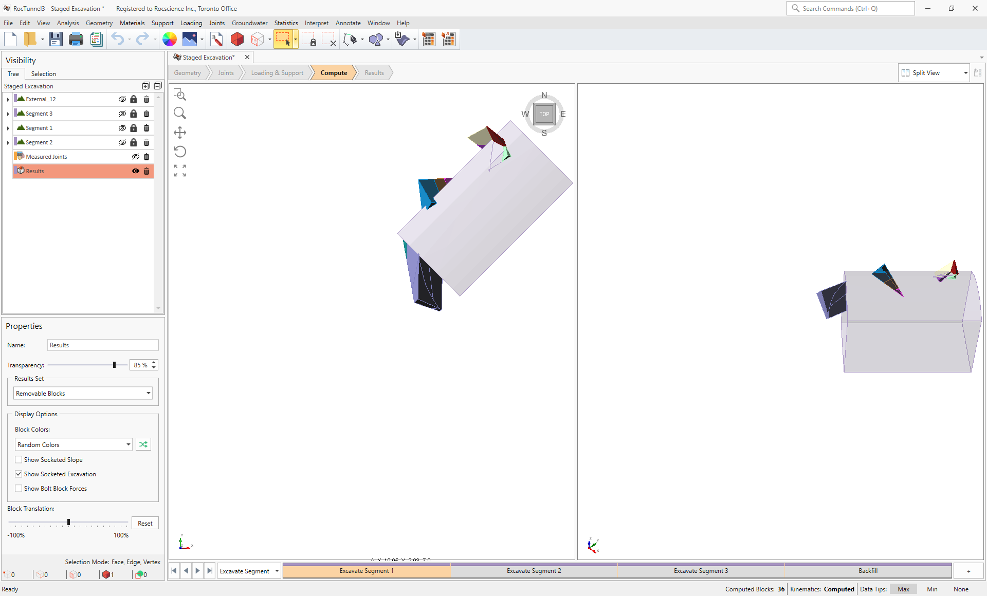
To view all valid blocks in each stage:
- Select the Excavate Segment 1 stage from the Stage tabs.
- Select the Excavate Segment 2 stage from the Stage tabs.
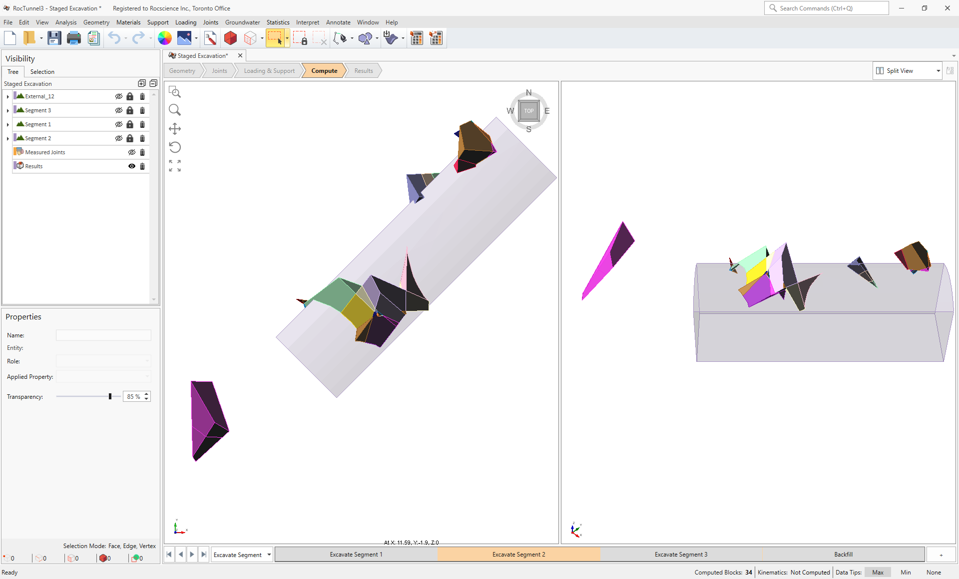
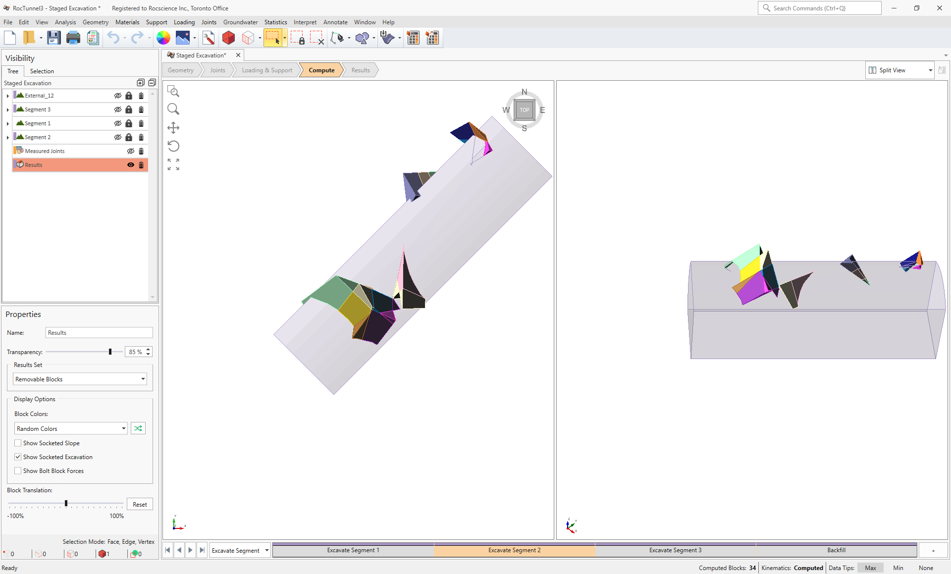
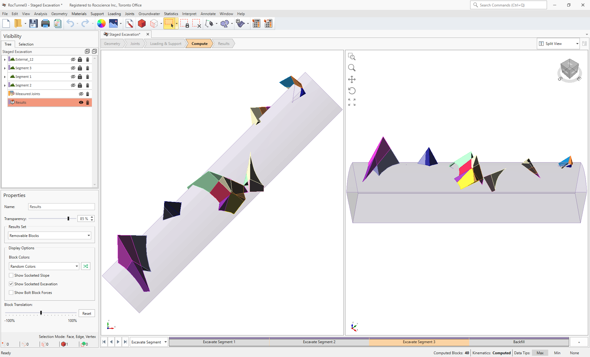
3D View of all Valid Blocks in Excavate Segment 2 stage - Select the Excavate Segment 3 stage from the Stage tabs.
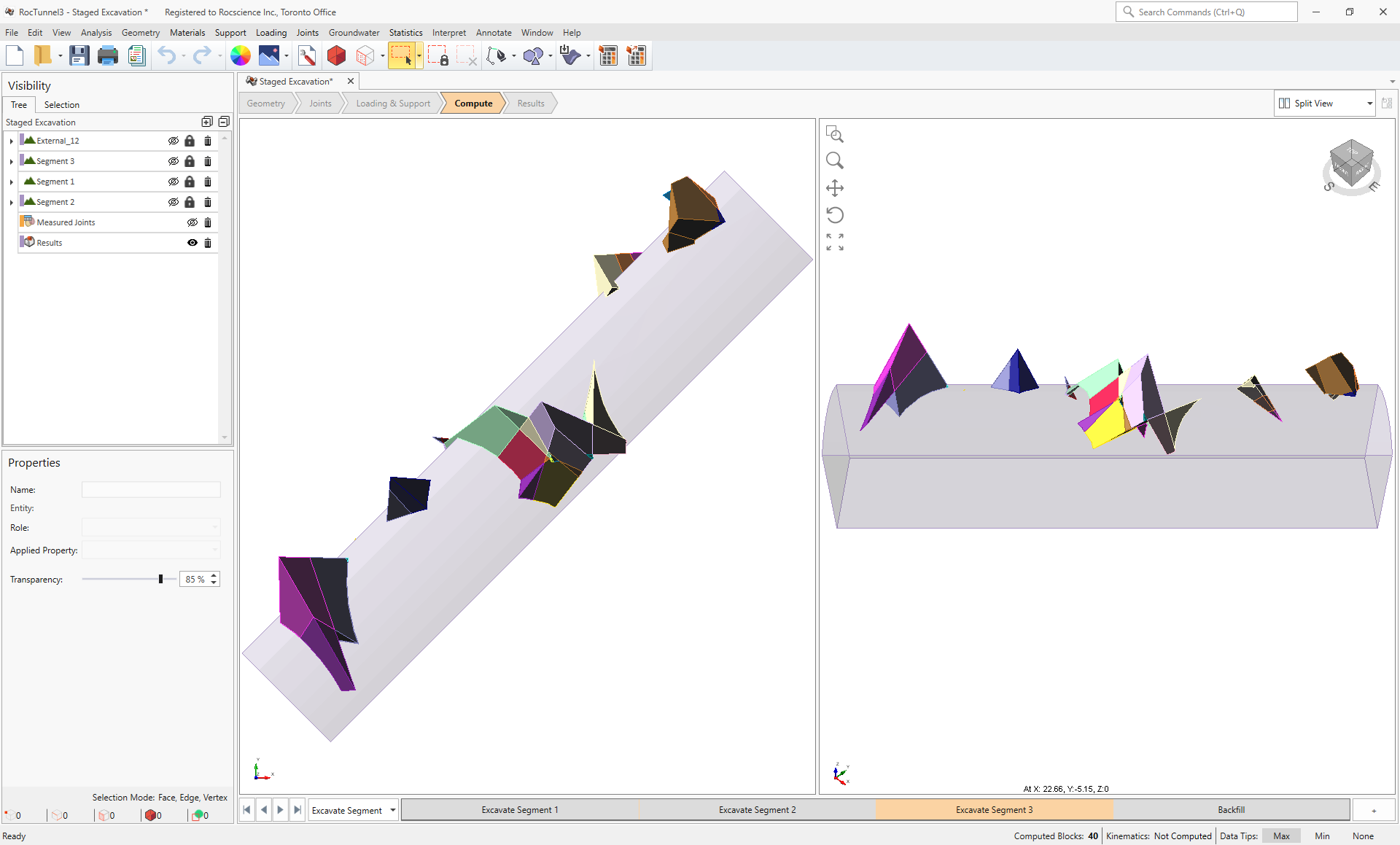
3D View of all Valid Blocks in Excavate Segment 3 stage - Select the Backfill stage from the Stage tabs.
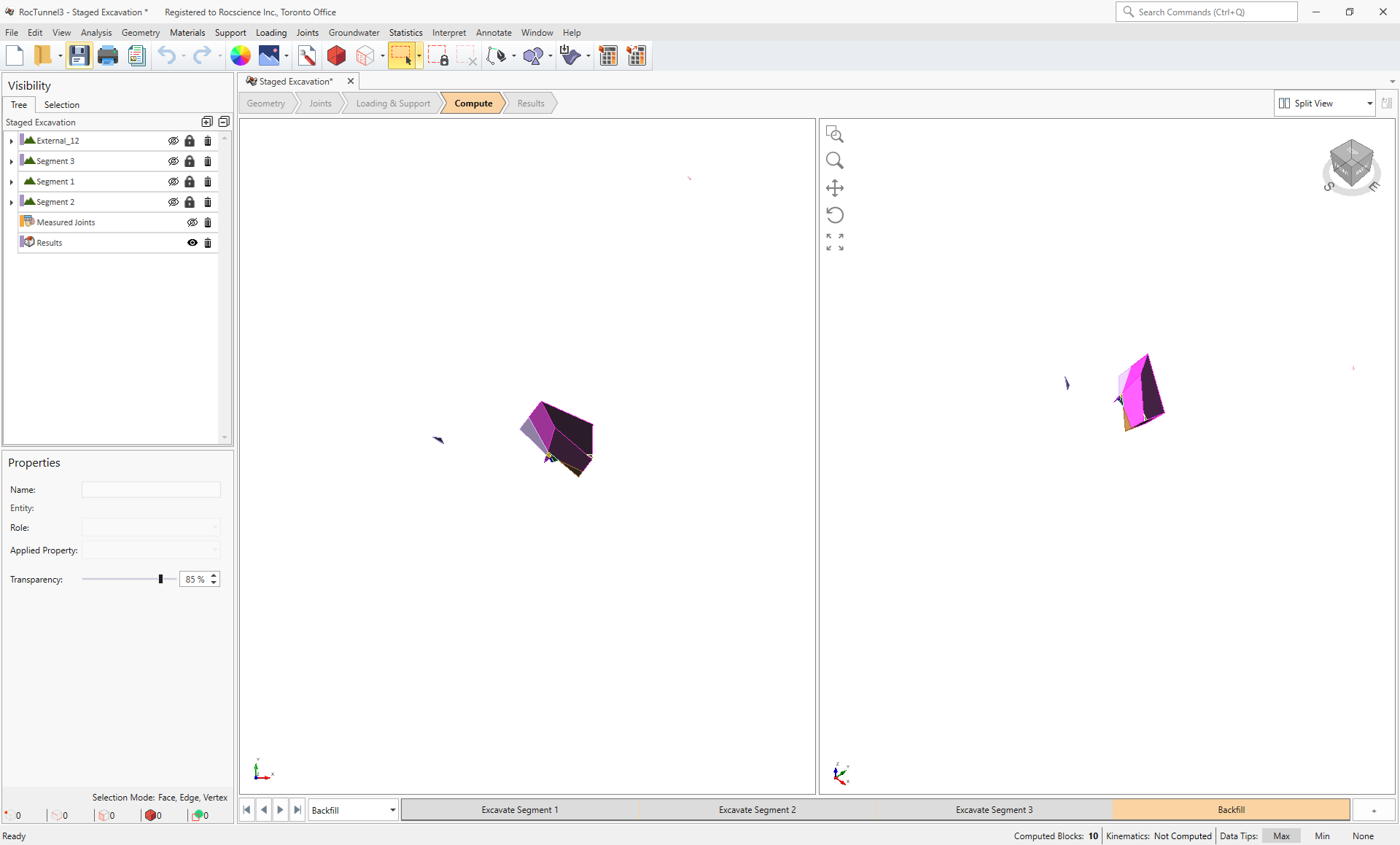
3D View of all Valid Blocks in Backfill stage
Compute Blocks only determines the geometry of the blocks. In order to obtain other information such as removability and the factor of safety, Compute Kinematics needs to be run.
4.2 Compute Kinematics
The second and final compute step is to compute the removability, forces, and factor of safety for each of the valid blocks.
To compute the block kinematics:
- Ensure that the Compute workflow tab is the active workflow.
- Select Analysis > Compute Kinematics
 . As compute is run, the progress bar reports the compute status.
 - If the current Results Set is not already set to Removable Blocks, then select the Results node from the Visibility Tree and set Results Set = Removable Blocks.
To view removable blocks in each stage:
- Select the Excavate Segment 1 stage from the Stage tabs.
3D View of Removable Blocks in Excavate Segment 1 stage - Select the Excavate Segment 2 stage from the Stage tabs.
3D View of Removable Blocks in Excavate Segment 2 stage - Select the Excavate Segment 3 stage from the Stage tabs.
3D View of Removable Blocks in Excavate Segment 3 stage - Select the Backfill stage from the Stage tabs. No removable blocks exist in this stage since the entire excavation is filled.
3D View of Removable Blocks in Backfill stage
Staged excavations and backfill can affect the number of valid blocks formed. But most importantly, introducing additional excavation faces increases the number of blocks with unsupported free faces which are geometrically removable and can slide or fall into the excavation.
5.0 Stage Plot
As seen from toggling across the various stages in the 3D CAD View, a different number of Removable blocks are formed as the tunnel is excavated further. In some cases, as the excavation face is advanced, new potential block instabilities are created since they are now exposed and unsupported in the rock mass along the excavation. In other cases, blocks may be excavated away and no longer pose a failure risk. The Plot Stage Data feature in RocTunnel3 allows users to visualize the trend in key block parameters across the stages.
To create a stage plot:
- Select Interpret > Plot Stage Data
- In the Plot Results by Stage dialog:
- Set Data to Plot = Sum Volume Failed Blocks
- Select the Excavate Segment 1, Excavate Segment 2, Excavate Segment 3, and Backfill stage checkboxes.
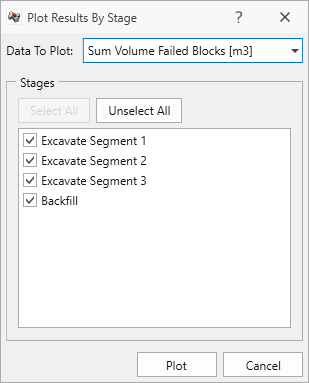
Plot Results by Stage dialog - Click Plot to generate the plot.
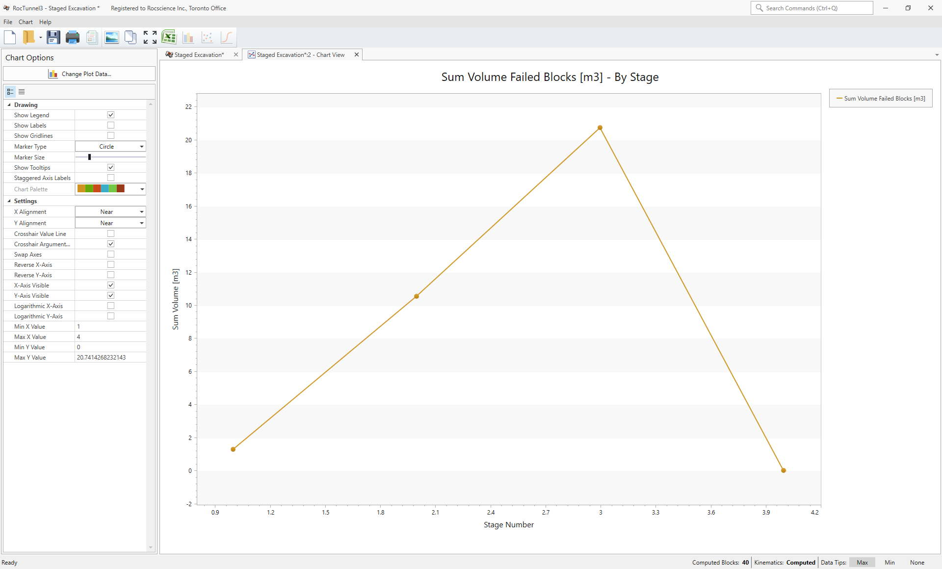
As the excavation advances from the Excavate Segment 1 stage to Excavate Segment 3 stage, the total sum of failed block volumes is increasing. In the Backfill stage, no blocks are formed since the entire excavation is backfilled, so it makes sense to have zero failed block volumes.
This concludes Tutorial 5.