6 - Staged Support Design
1.0 Introduction
This tutorial introduces the concept of stageable support design in which support such as shotcrete and bolts may be installed and removed in certain stages to accommodate different support demands in each stage of the excavation. This tutorial uses a simple extruded 30 m-long tunnel with a 5.5 m by 5.5 m drive, oriented at Trend/Plunge of 0/45 degrees (from the finished model in Tutorial 5). In each stage, a 10 m-long length of tunnel is excavated and in the final stage, all the previously excavated volumes are backfilled. We are going to analyze the blocks formed in each stage, particularly blocks which have less than the Design Factor of Safety, and implement appropriate rock support measures at each stage.
Finished Product
The finished product of this tutorial can be found in the Staged Support Design.roctunnel_model file. All tutorial files installed with RocTunnel3 can be accessed by selecting File > Recent Folders > Tutorials Folder from the RocTunnel3 main menu.
2.0 Opening the Starting File
- Select File > Recent > Tutorials Folder in the menu.
- In the Staged Support Design folder, open the file Staged Support Design - starting file.roctunnel_model.
This model already has the following defined and provides a good starting point to start defining stages:
- Project Settings
- Material Properties
- External Geometry
- Joint Properties
- Measured Joints
2.1 Project Settings
Review the Project Settings.
- Select Analysis > Project Settings

- Select the Units tab.
- Ensure Units = Metric, stress as kPa.
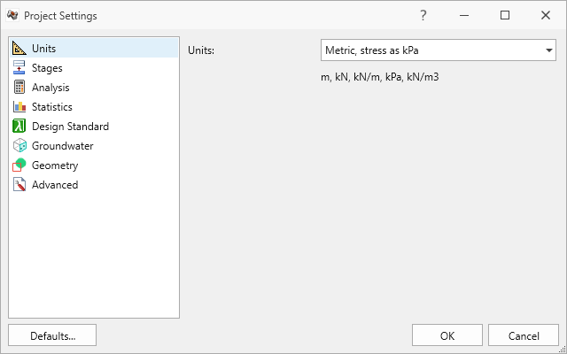
Units tab in Project Settings dialog - Select the Stages tab. By default, projects have only one stage.
- Ensure Number of Stages = 4.
You should see Excavate Segment 1, Excavate Segment 2, Excavate Segment 3, and Backfill in the table.
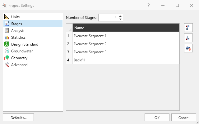
Stages tab in Project Settings dialog Note: Stages can be renamed, inserted, or removed from the Stages tab of the Project Settings dialog. To quickly add a stage, you can also optionally select the + button in from the Stage tabs at the bottom of the application window. - Select the Analysis tab.
- Ensure Design Factor of Safety = 1.2.
- Ensure Successive Failure = ON. It is important in support design to identify key blocks and furthest possible extent of instabilities for strategic bolt placement and bolt length selection.
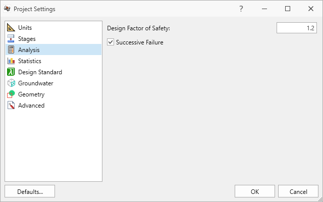
Analysis tab in Project Settings dialog - Click Cancel to exit the dialog.
2.2 Material Properties
Review the Material Properties.
- Select Materials > Define Materials

- Two (2) material properties are defined.
The Rock material property has: - Unit Weight = 26 kN/m3.
- No Water Surface applied.
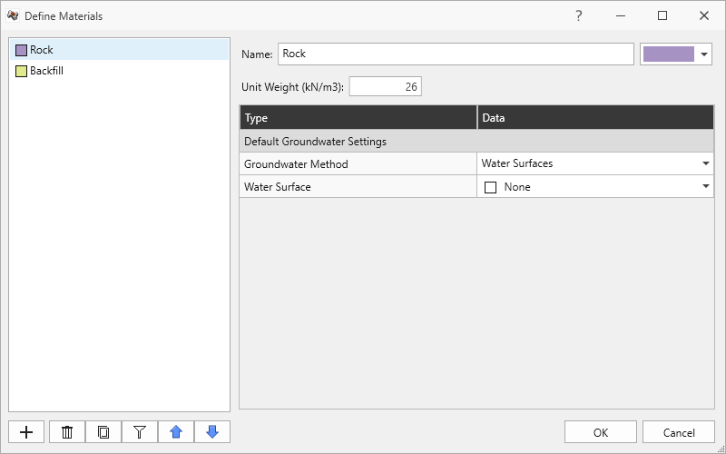
Rock material property in Define Materials dialog - The Backfill material property has:
- Unit Weight = 20 kN/m3.
- No Water Surface applied.
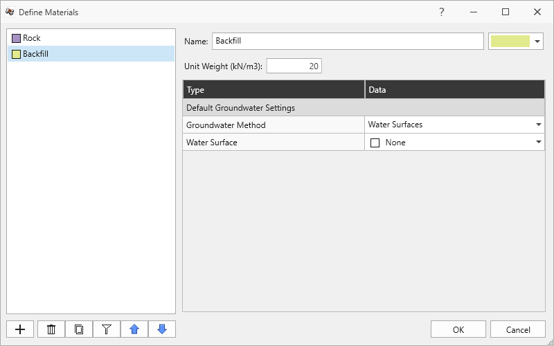
Backfill material property in Define Materials dialog - Click Cancel to exit the dialog.
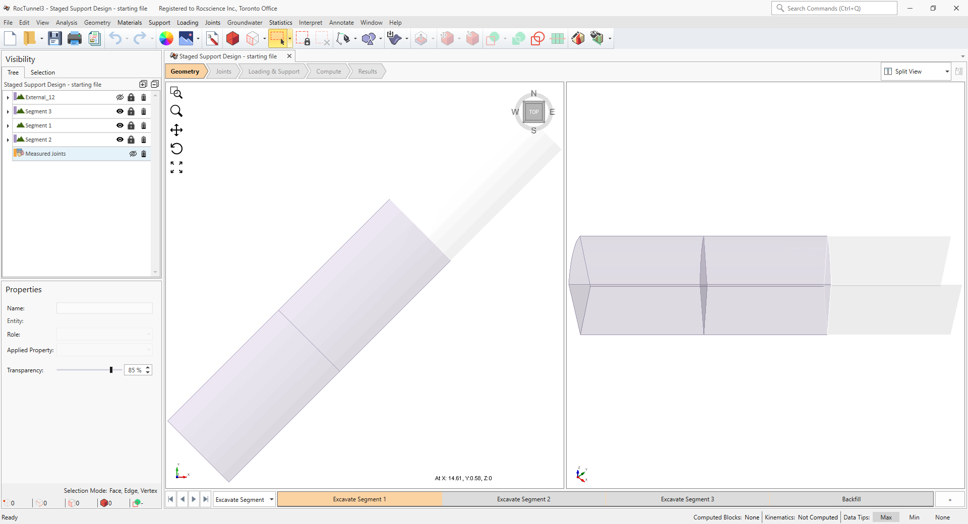
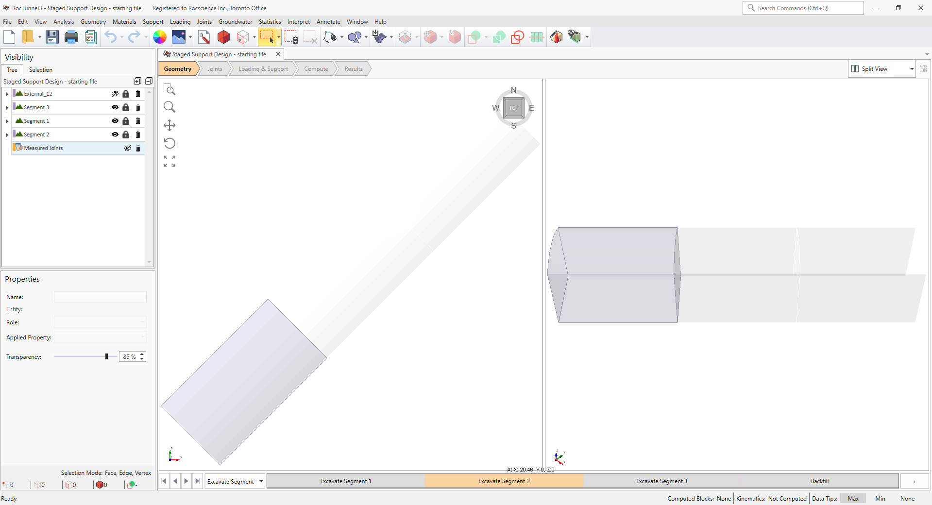
2.3 External Geometry
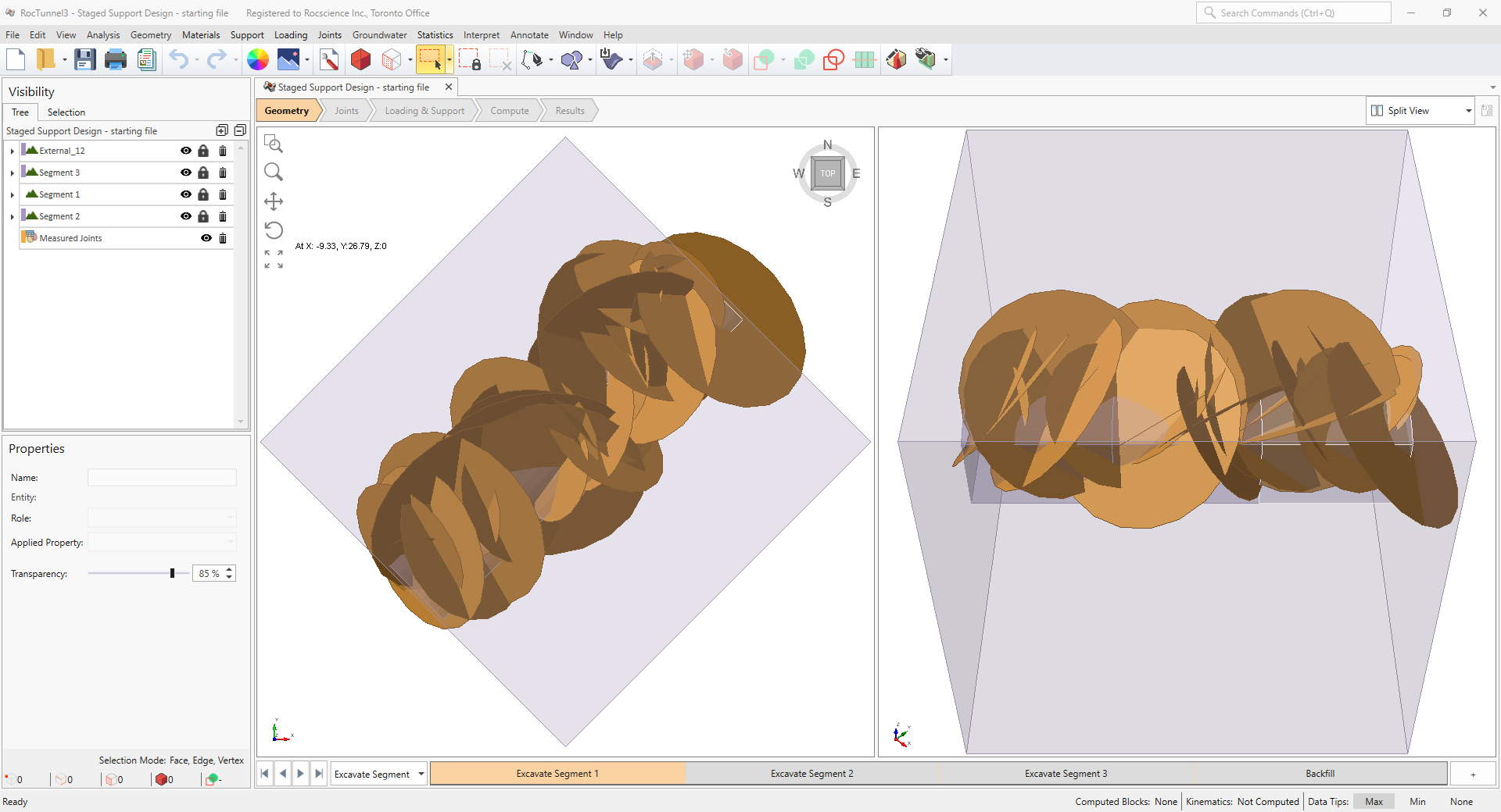
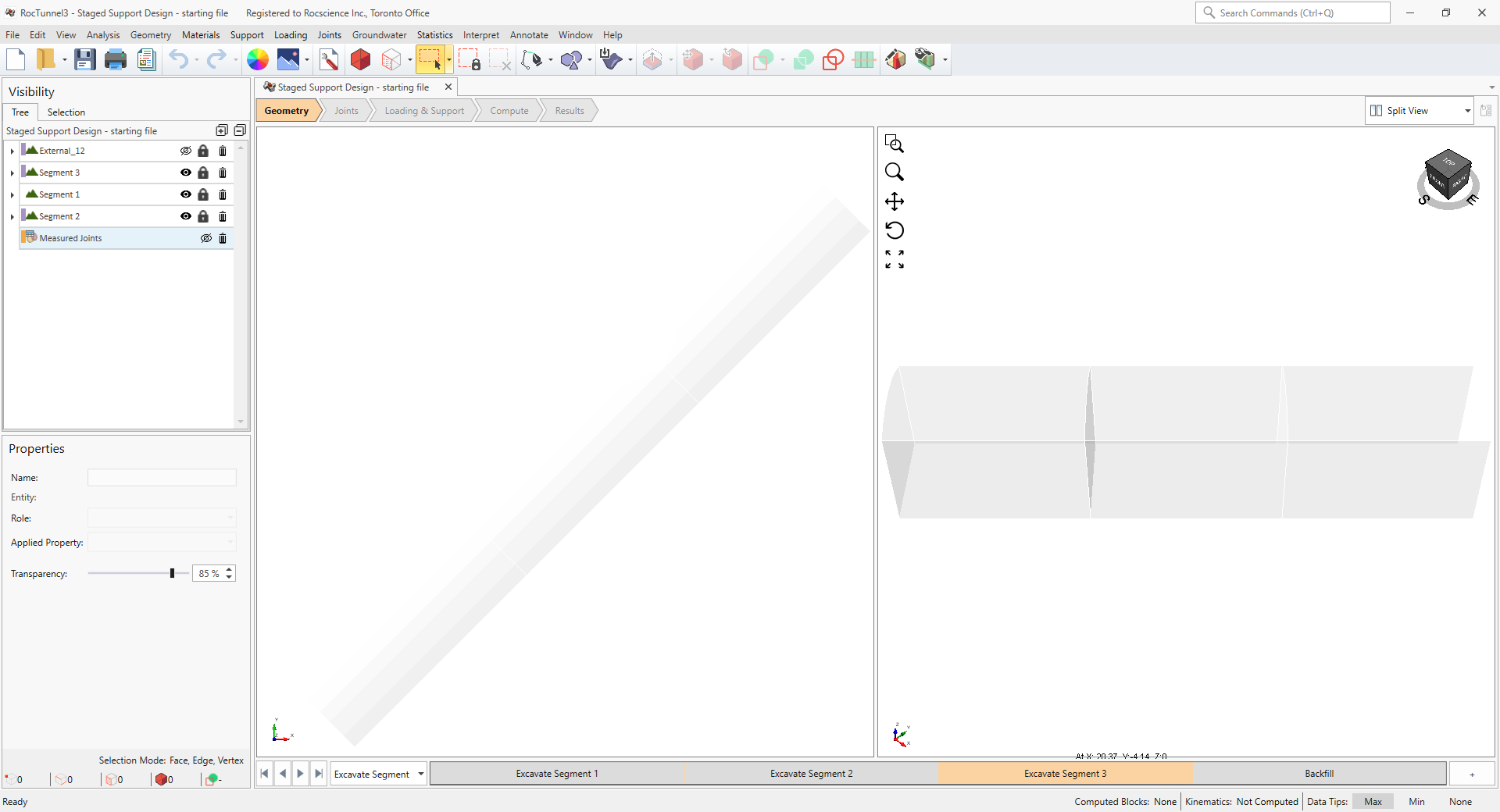
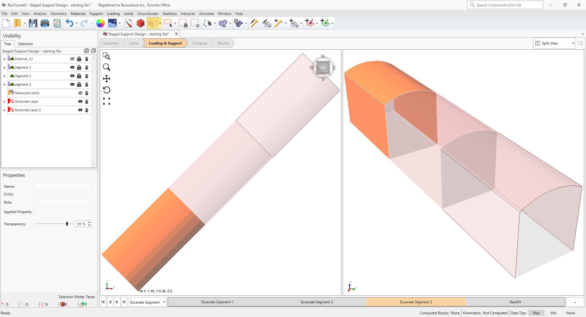
The External consists of volume pieces assigned with Rock material property. The Segment 1, Segment 2, and Segment 3 External pieces represent the volume regions of the planned staged excavations.
To better visualize the tunnel:
- Turn off the visibility of External_12 node from the Visibility Tree by clicking the eye icon.
- Turn off the visibility of Measured Joints node from the Visibility Tree by clicking the eye icon.
In the Excavate Segment 1 stage the Assigned Property is:
- Segment 1 = No Material
- Segment 2 = Rock
- Segment 3= Rock
In the Excavate Segment 2 stage, the Assigned Property is:
- Segment 1 = No Material
- Segment 2 = No Material
- Segment 3 = Rock
In the Excavate Segment 3 stage the Assigned Property is:
- Segment 1 = No Material
- Segment 2 = No Material
- Segment 3 = No Material
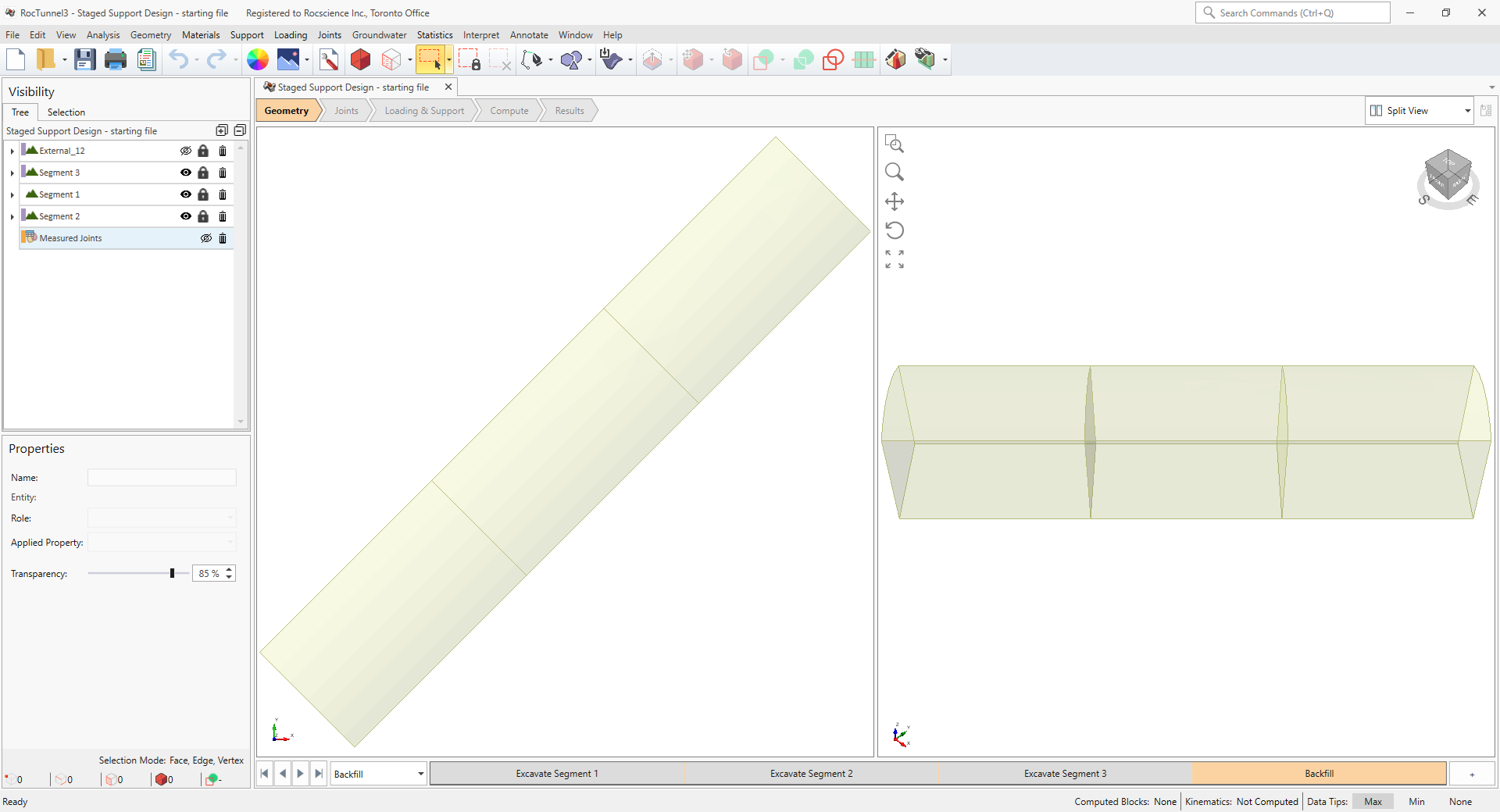
In the Backfill stage, the Assigned Property is:
- Segment 1 = Backfill
- Segment 2 = Backfill
- Segment 3 = Backfill
See Tutorial 5 for steps on how the staged excavation and backfill was assigned.
2.4 Joint Properties
Review the Joint Properties.
- Select Joints > Define Joint Properties

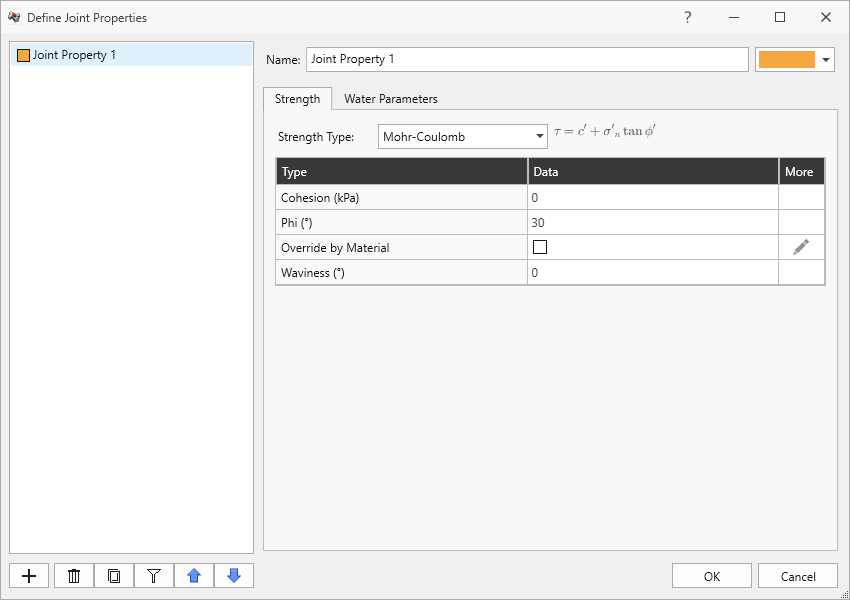
- One (1) joint property is defined. The Joint Property 1 joint property has:
- Strength Type = Mohr-Coulomb
- Cohesion = 0 kPa
- Friction Angle = 30 degrees
- Override by Material = OFF
- Waviness = 0 degrees
- Water Pressure Method = Uniform.
- Water Pressure = 200 kPa.
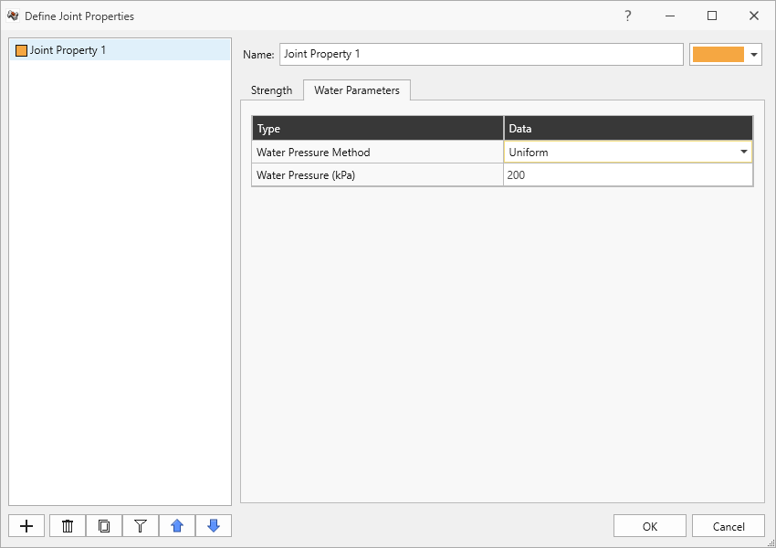
Joint Property 1 joint property in Water Parameters tab of Define Joint Properties dialog - Click Cancel to exit the dialog.
2.5 Measured Joints
Review the Measured Joints.
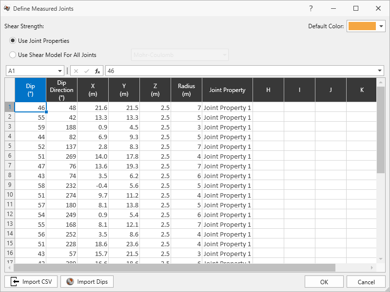
- Select Joints > Define Measured Joints

30 Measured Joints are defined and listed in order of Dip, Dip Direction, X, Y, Z, Radius, and Joint Property.
| Dip | Dip Direction | X | Y | Z | Radius | Joint Property |
| 46 | 48 | 21.6 | 21.5 | 2.5 | 7 | Joint Property 1 |
| 55 | 42 | 13.3 | 13.3 | 2.5 | 5 | Joint Property 1 |
| 59 | 188 | 0.9 | 4.5 | 2.5 | 3 | Joint Property 1 |
| 44 | 82 | 6.9 | 9.3 | 2.5 | 5 | Joint Property 1 |
| 52 | 137 | 2.8 | 8.3 | 2.5 | 7 | Joint Property 1 |
| 51 | 269 | 14 | 17.8 | 2.5 | 4 | Joint Property 1 |
| 47 | 76 | 13.6 | 19.3 | 2.5 | 7 | Joint Property 1 |
| 43 | 74 | 3.5 | 6.2 | 2.5 | 6 | Joint Property 1 |
| 58 | 232 | -0.4 | 5.6 | 2.5 | 5 | Joint Property 1 |
| 51 | 274 | 9.7 | 11.2 | 2.5 | 4 | Joint Property 1 |
| 57 | 180 | 8.1 | 13.8 | 2.5 | 5 | Joint Property 1 |
| 54 | 249 | 0.9 | 5.4 | 2.5 | 6 | Joint Property 1 |
| 55 | 168 | 8.1 | 12.1 | 2.5 | 7 | Joint Property 1 |
| 56 | 252 | 3.5 | 8.6 | 2.5 | 4 | Joint Property 1 |
| 51 | 228 | 18.6 | 23.6 | 2.5 | 4 | Joint Property 1 |
| 43 | 57 | 15.7 | 21.5 | 2.5 | 3 | Joint Property 1 |
| 42 | 289 | 16.6 | 18.6 | 2.5 | 6 | Joint Property 1 |
| 55 | 27 | 15.9 | 23.7 | 2.5 | 5 | Joint Property 1 |
| 54 | 212 | 19 | 23.9 | 2.5 | 3 | Joint Property 1 |
| 49 | 72 | 12.8 | 15.6 | 2.5 | 4 | Joint Property 1 |
| 41 | 175 | 9.2 | 10.2 | 2.5 | 7 | Joint Property 1 |
| 43 | 227 | 7.7 | 13.5 | 2.5 | 6 | Joint Property 1 |
| 56 | 280 | 15.7 | 22.8 | 2.5 | 3 | Joint Property 1 |
| 47 | 228 | 3.2 | 7.4 | 2.5 | 7 | Joint Property 1 |
| 56 | 282 | 12.5 | 14.3 | 2.5 | 5 | Joint Property 1 |
| 58 | 38 | 15.8 | 19.5 | 2.5 | 5 | Joint Property 1 |
| 53 | 151 | 14.3 | 19.9 | 2.5 | 7 | Joint Property 1 |
| 46 | 83 | 18.7 | 20.5 | 2.5 | 5 | Joint Property 1 |
| 52 | 54 | 13.7 | 15 | 2.5 | 4 | Joint Property 1 |
| 43 | 96 | 6.2 | 13 | 2.5 | 4 | Joint Property 1 |
- Click Cancel to exit the dialog.
Note that if you select any External Geology node, the colors in the Stage tabs indicate the Material Property assigned at each stage.
3.0 Compute
RocTunnel3 has a two-part compute process.
3.1 Compute Blocks
The first step is to compute the blocks which may potentially be formed by the intersection of joints with other joints and the intersection of joints with the free surface.
To compute the blocks:
- Navigate to the Compute workflow tab

- Select Analysis > Compute Blocks

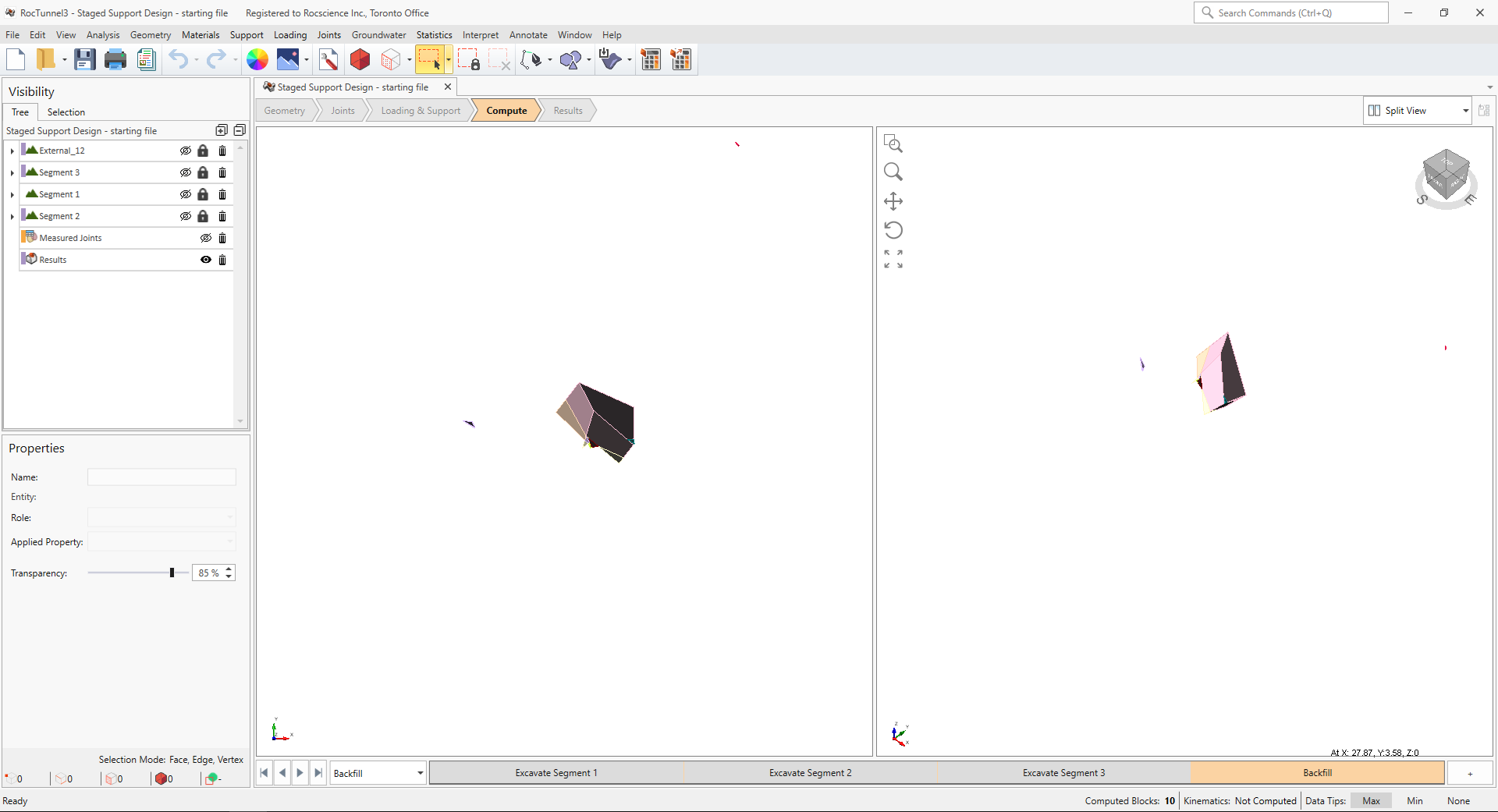
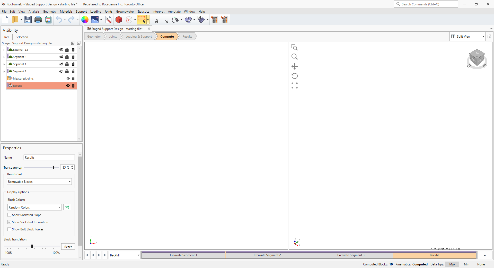
As compute is run, the progress bar reports the compute status. Once compute is finished, the Results node is added to the Visibility Tree and All Valid Blocks are blocks are shown in the 3D View. The Results node consists of the collection of valid blocks and the socketed excavation. The original External and Measured Joints visibility is turned off.
Once compute is finished, the blocks are coloured according to the Block Color option (Random Colors) set in the Results node's Properties pane.
To view all valid blocks in each stage:
- Select the Excavate Segment 1 stage from the Stage tabs.
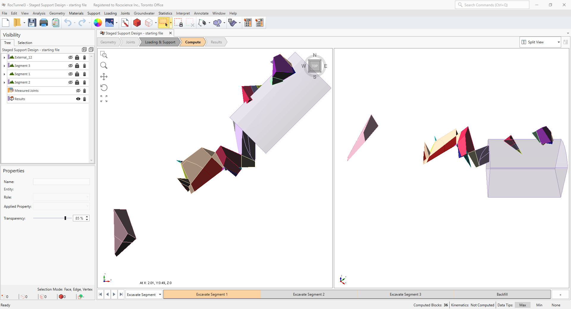
3D View of all Valid Blocks in Excavate Segment 1 stage - Select the Excavate Segment 2 stage from the Stage tabs.
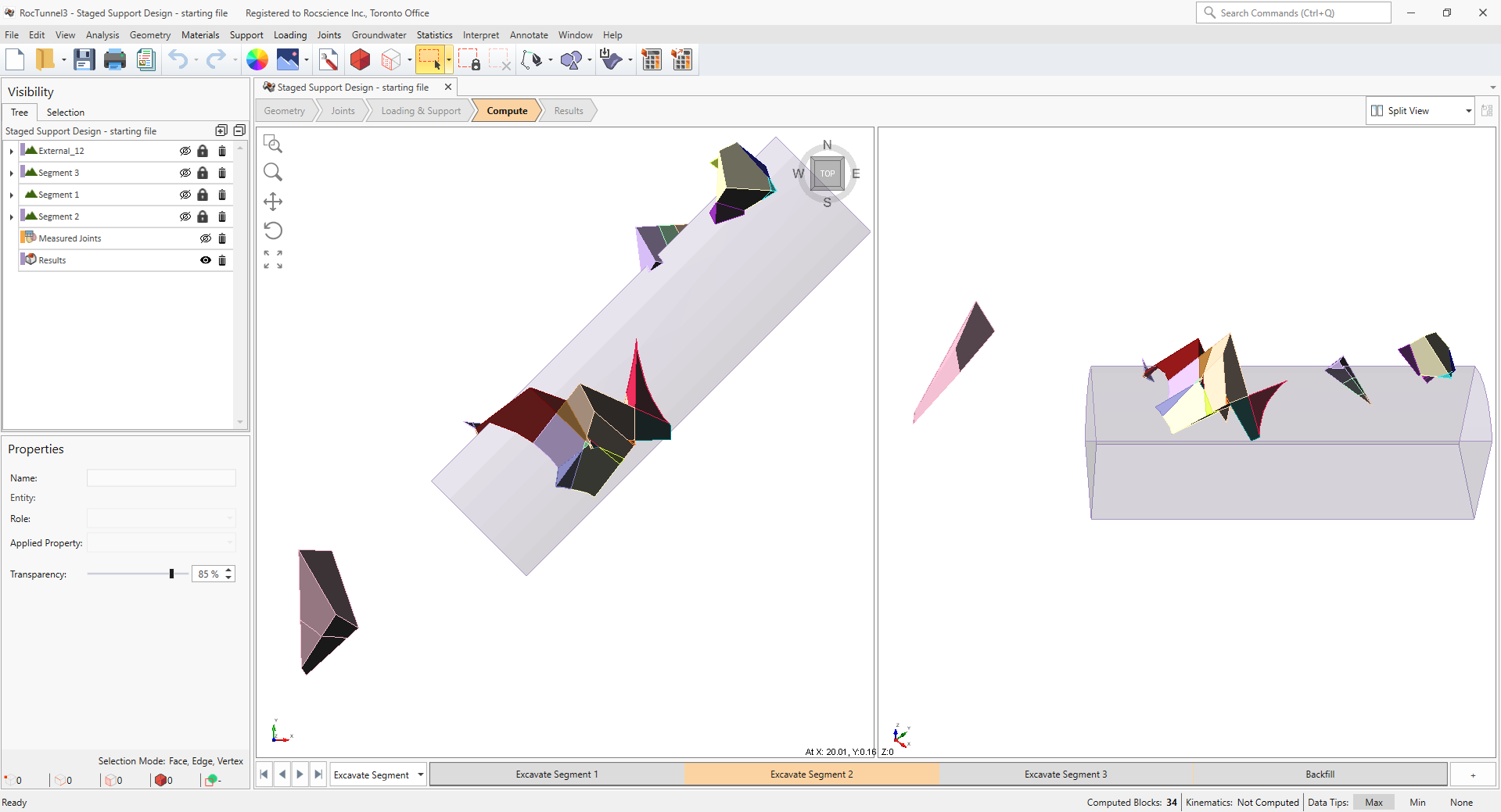
3D View of all Valid Blocks in Excavate Segment 2 stage - Select the Excavate Segment 3 stage from the Stage tabs.
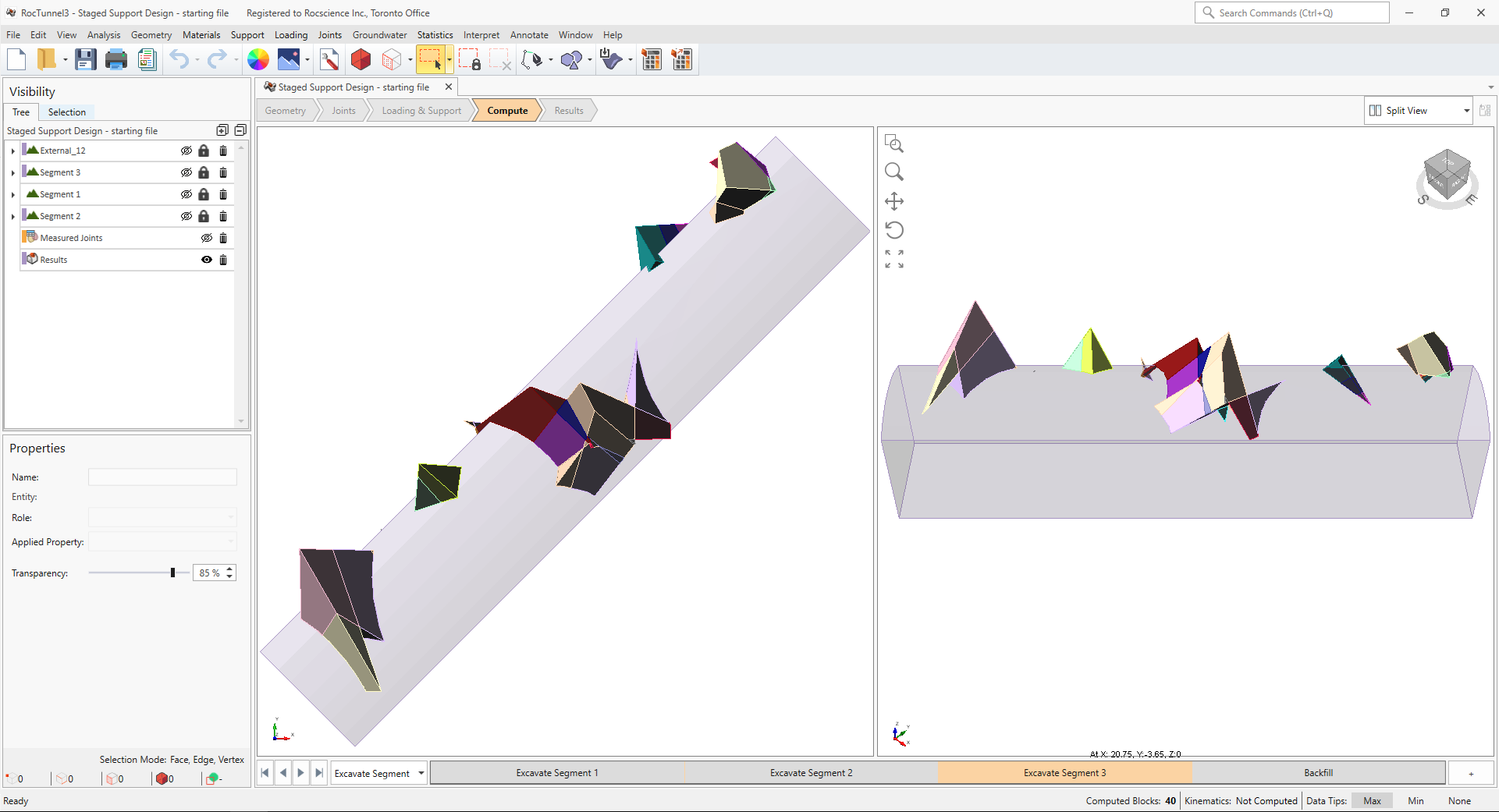
3D View of all Valid Blocks in Excavate Segment 3 stage - Select the Backfill stage from the Stage tabs.
3D View of all Valid Blocks in Backfill stage
Compute Blocks only determines the geometry of the blocks. In order to obtain other information such as the factor of safety, Compute Kinematics needs to be run.
3.2 Compute Kinematics
The second and final compute step is to compute the removability, forces, and factor of safety for each of the valid blocks.
To compute the block kinematics:
- Ensure that the Compute workflow tab is the active workflow.
- Select Analysis > Compute Kinematics
 . As compute is run, the progress bar reports the compute status.
 - If the current Results Set is not already set to Removable Blocks, then select the Results node from the Visibility Tree and set the Results Set = Removable Blocks.
To view removable blocks in each stage:
- Select the Excavate Segment 1 stage from the Stage tabs.
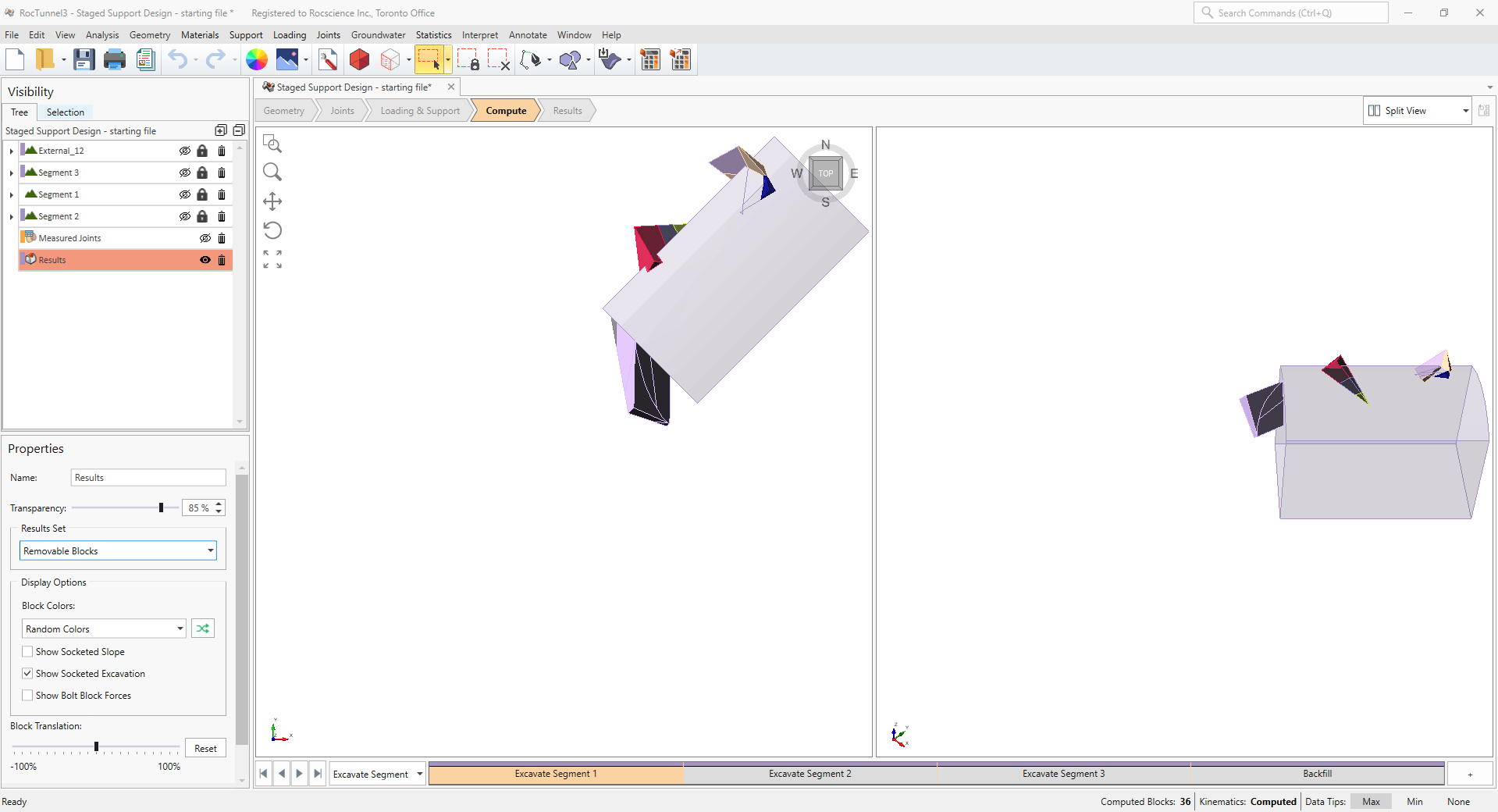
3D View of Removable Blocks in Excavate Segment 1 stage - Select the Excavate Segment 2 stage from the Stage tabs.
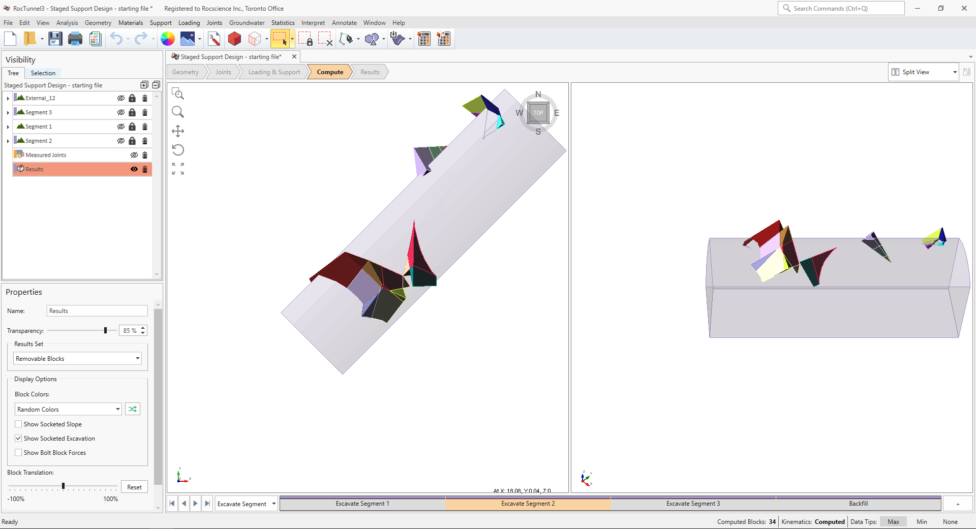
3D View of Removable Blocks in Excavate Segment 2 stage - Select the Excavate Segment 3 stage from the Stage tabs.
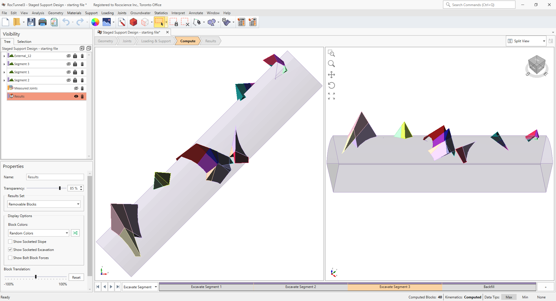
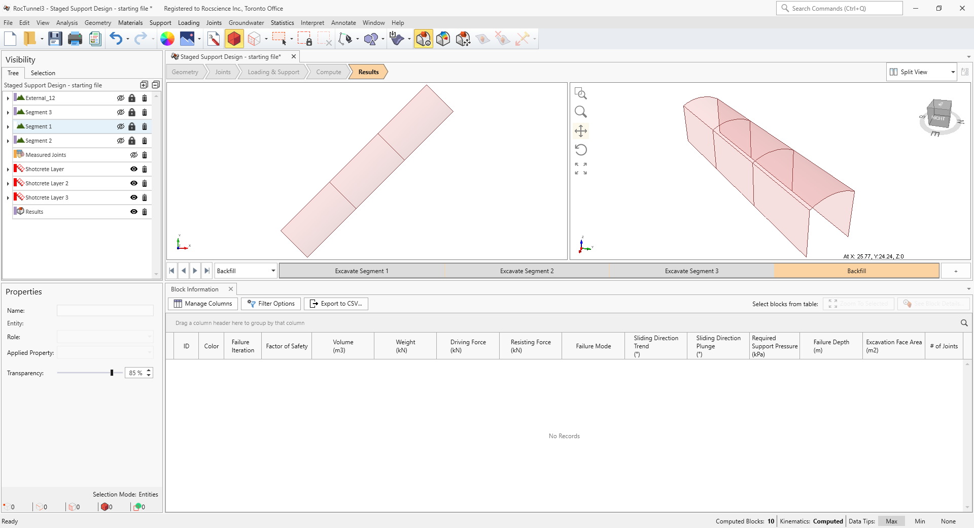
3D View of Removable Blocks in Excavate Segment 3 stage - Select the Backfill stage from the Stage tabs. No removable blocks exist in this stage since the entire excavation is filled.
3D View of Removable Blocks in Backfill stage
Staged excavations and backfill can affect the number of valid blocks formed. But most importantly, introducing additional excavation faces increases the number of blocks with unsupported free faces which are geometrically removable and can slide or fall into the excavation.
4.0 Interpreting Unsupported Results
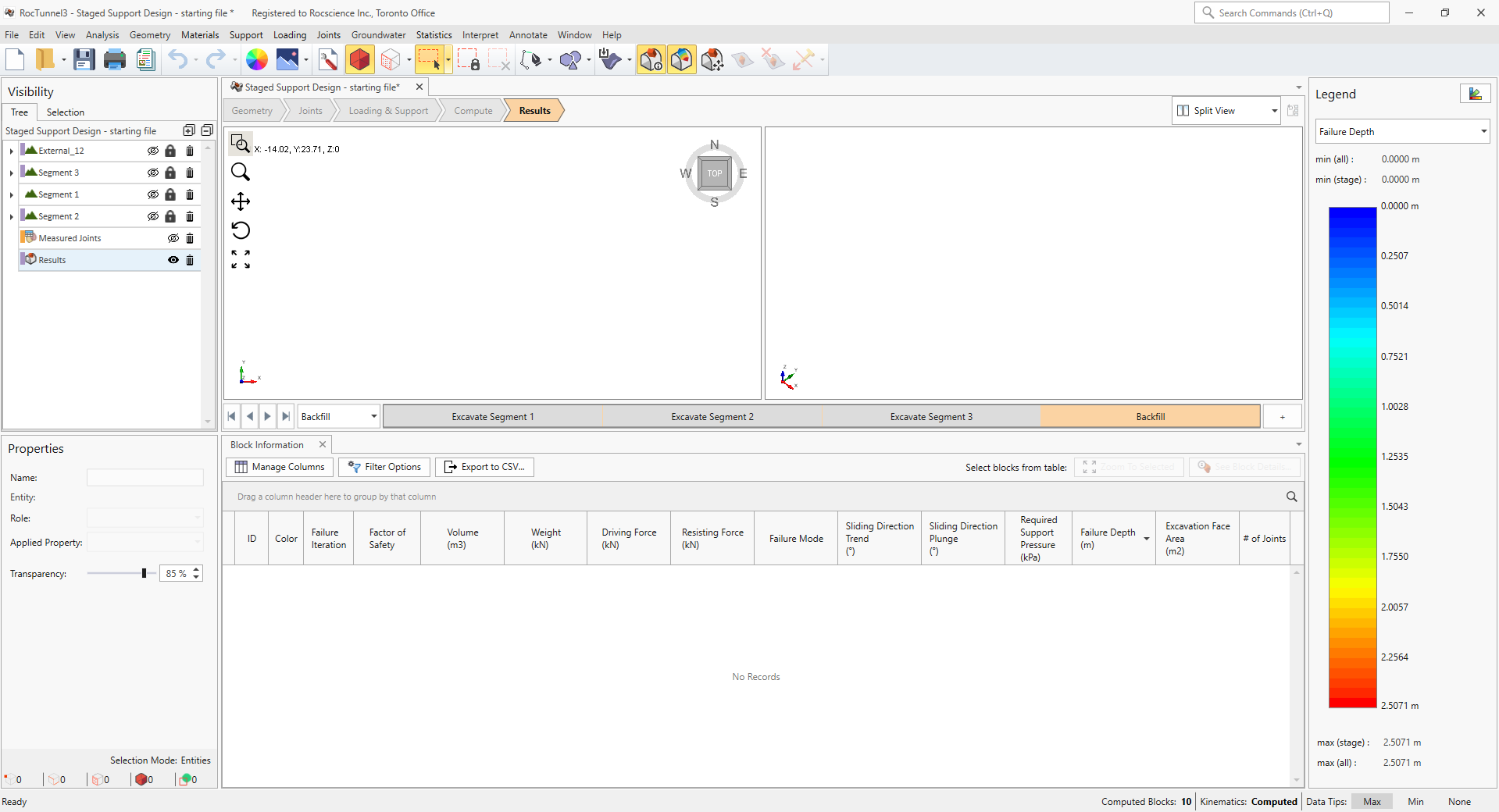
Once both blocks and kinematics are computed, all block results can be viewed in a table format.
4.1 Required Support Pressure
Failed blocks are blocks which do not meet the Design Factor of Safety and require additional support to achieve the Design Factor of Safety.
- The Required Support Pressure computed by RocTunnel3 represents the average support pressure applied normal to the excavation face in order to achieve the Design Factor of Safety. It provides a good starting place for designers to specify bolt capacity and bolt pattern spacing (Required Support Pressure is approximately equal to Bolt Force Capacity / (Bolt Spacing)^2 installed normal to excavation), or single spot bolt capacity (Required Support Pressure * Block Excavation Face Area is equal to Bolt Force Capacity installed normal to excavation)
- The Failure Depth computed by RocTunnel3, represents the distance measured from the excavation face to the deepest failed block socket in a direction normal to the excavation face. It provides a good estimation for the bolt length to anchor into competent rock mass. See the Definitions topic for more information on Failure Depth.
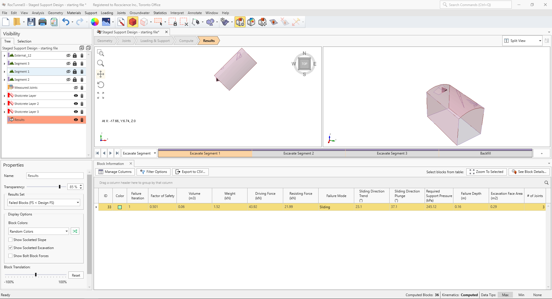
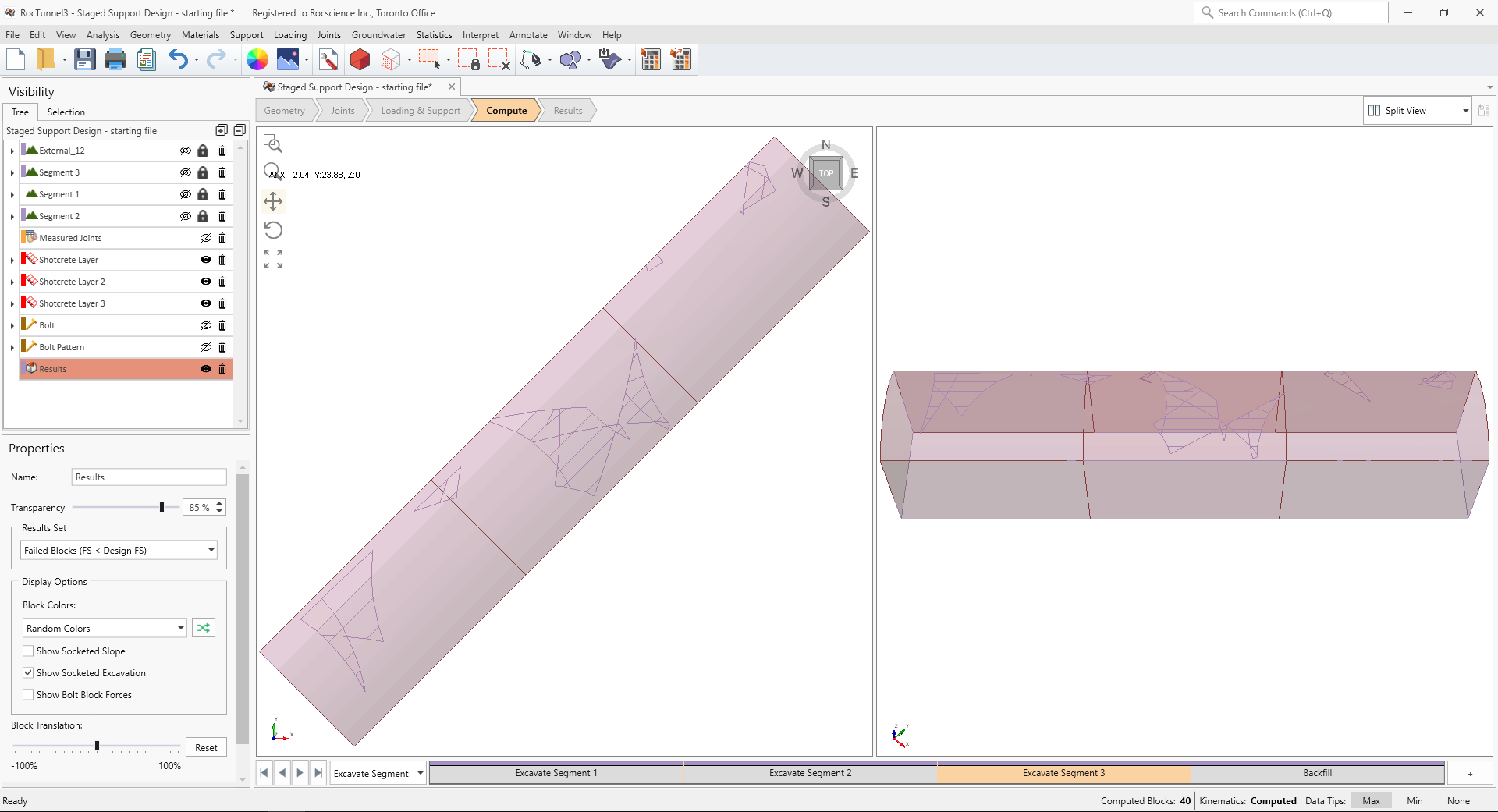
To view failed blocks:
- Navigate to the Result workflow tab

- Select the Results node from the Visibility Tree.
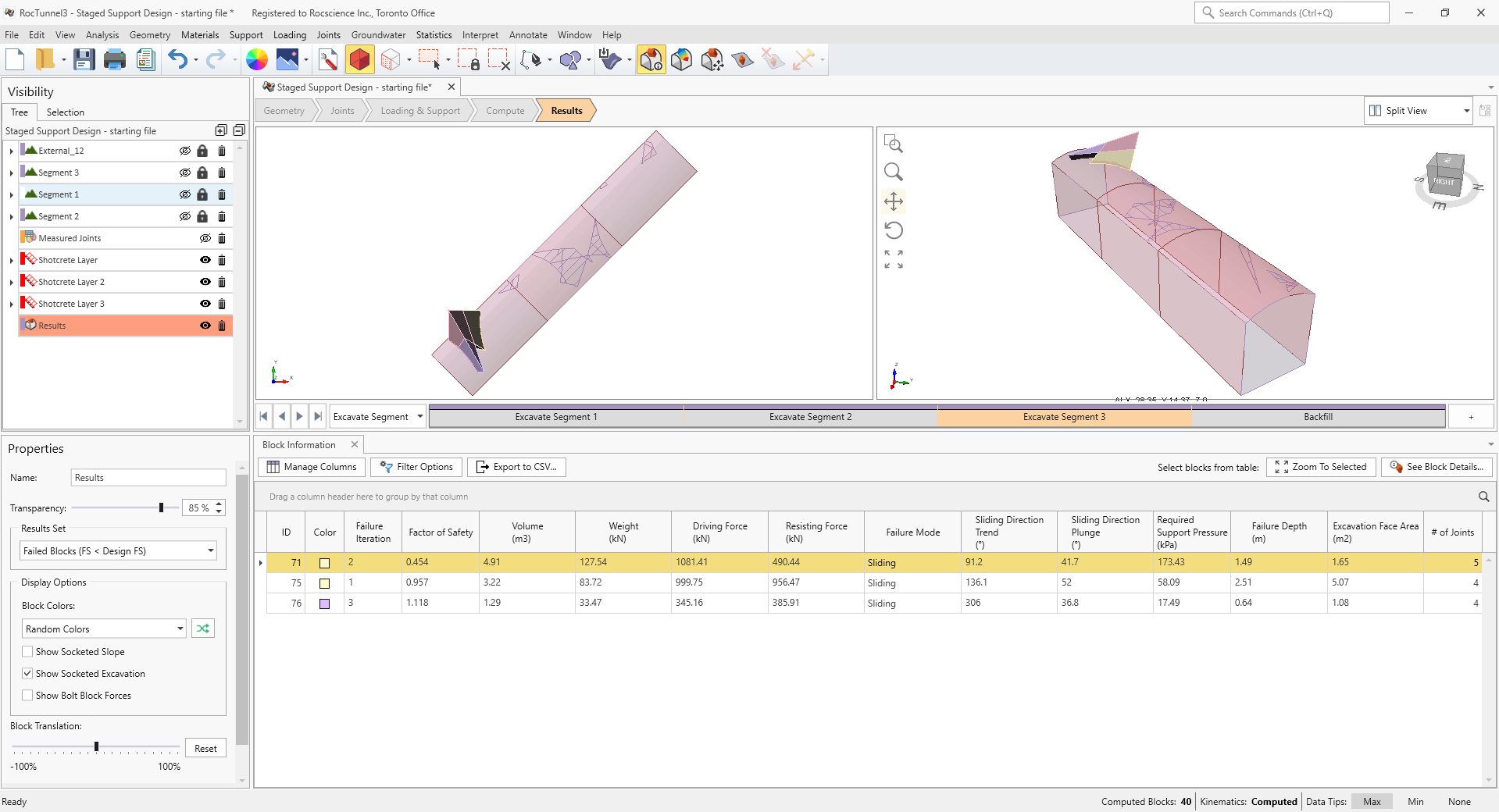
- Set Results Set = Failed (FS < Design FS). These are the subset of removable blocks which have factors of safety less than the Design Factor of Safety of 1.2.
- Select Interpret > Block Information

- Left-click the Required Support Pressure header twice to sort the rows in descending order by Required Support Pressure
- Select Interpret > Contour Blocks

- Set the Legend data to Required Support Pressure
- Select Interpret > Contour Options

- In the Contour Options dialog:
- Select Auto Range (All Stages). Selecting this option means that the contours are based on the min and max values across all stages.
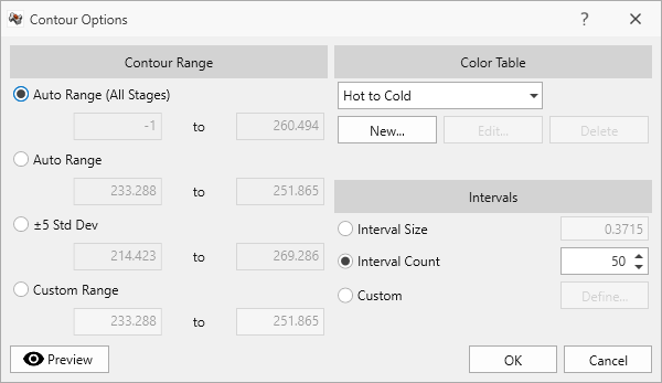
Contour Options dialog - Click OK.
- Select the Excavate Segment 1 stage from the Stage tabs.
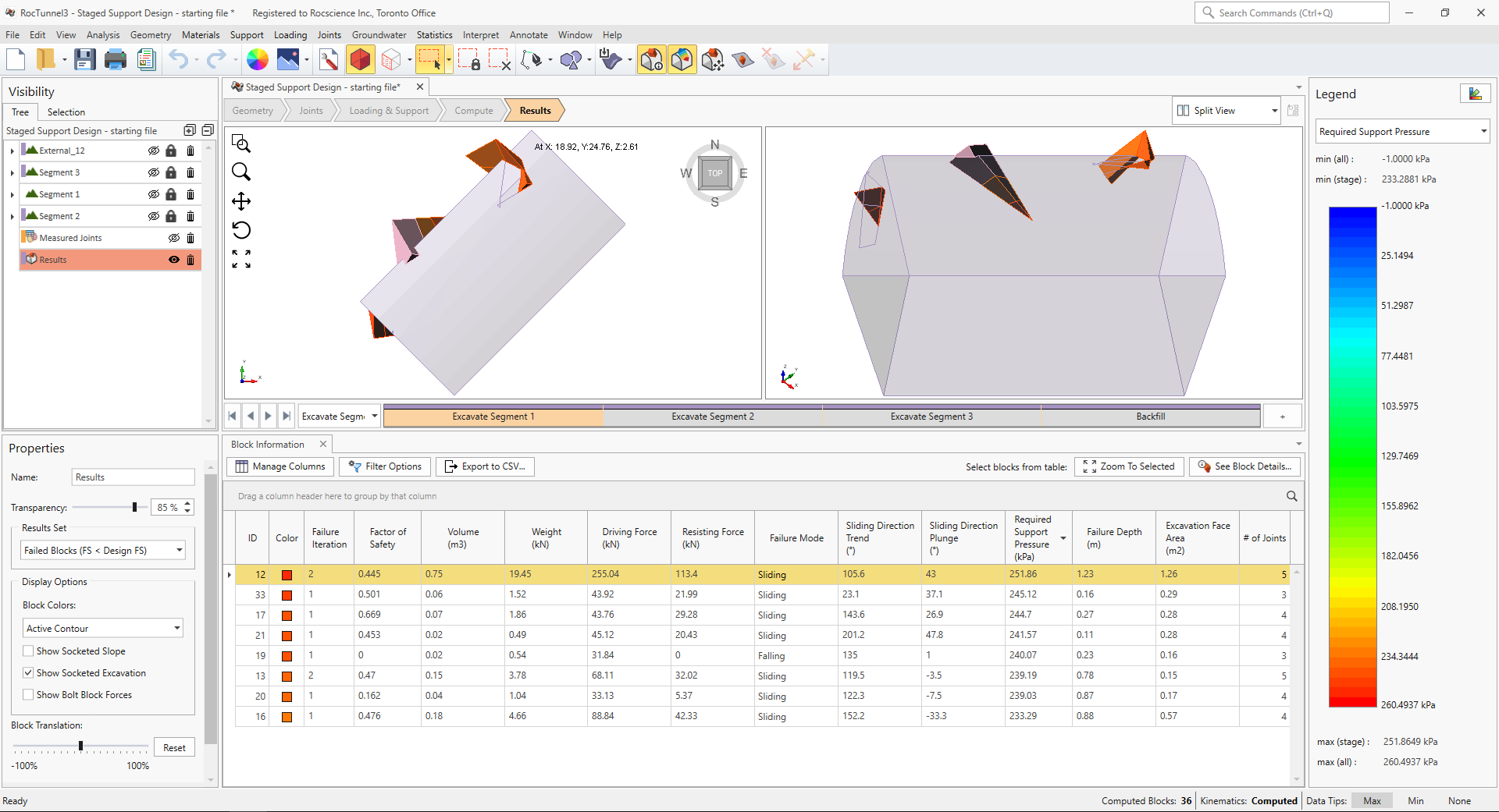
Failed Blocks contoured and sorted by Required Support Pressure in Excavate Segment 1 stage - Select the Excavate Segment 2 stage from the Stage tabs.
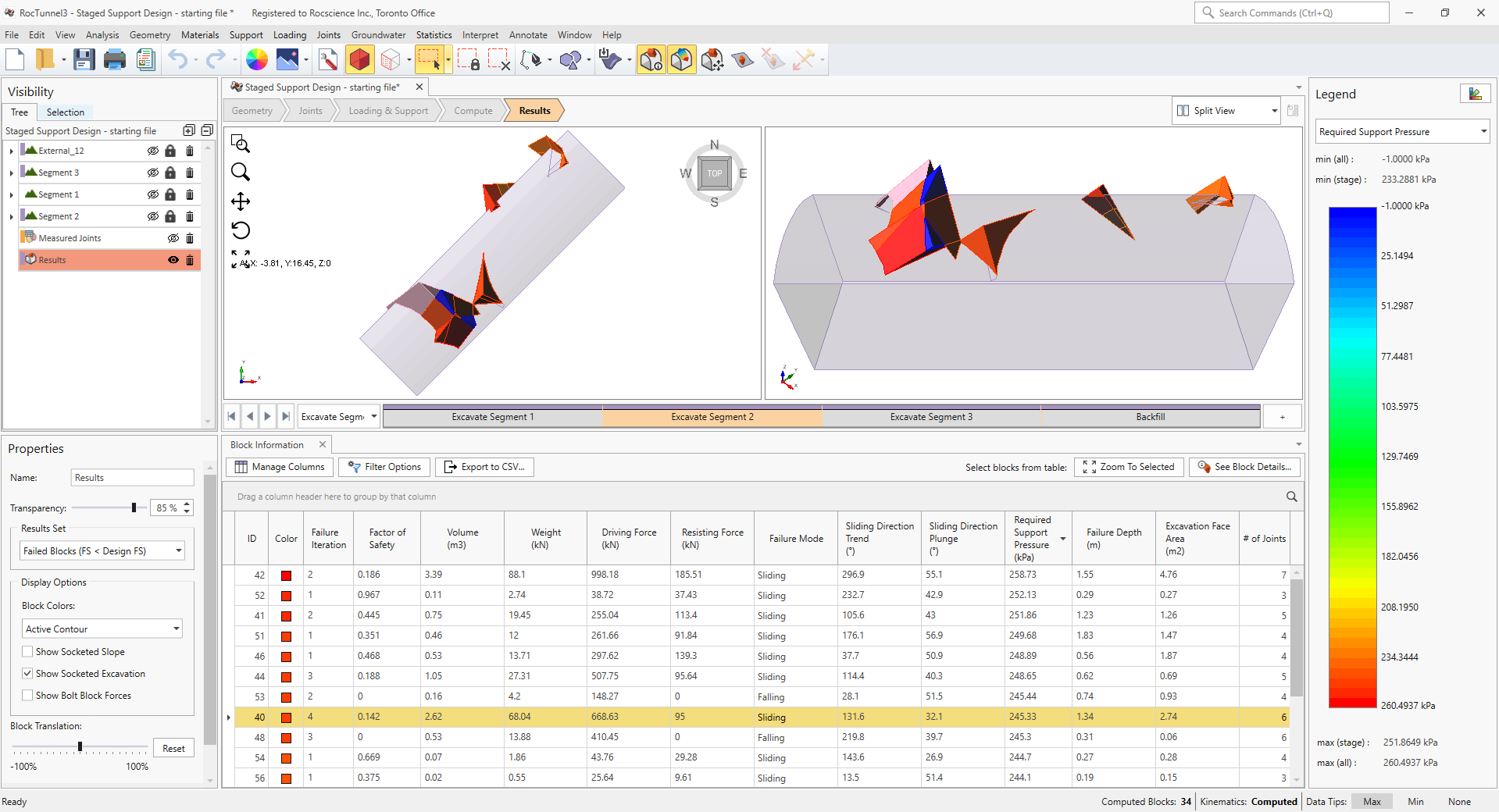
Failed Blocks contoured and sorted by Required Support Pressure in Excavate Segment 2 stage - Select the Excavate Segment 3 stage from the Stage tabs.
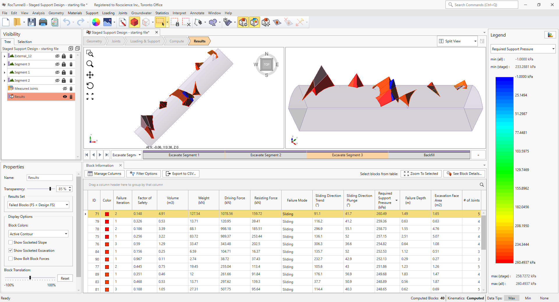
Failed Blocks contoured and sorted by Required Support Pressure in Excavate Segment 3 stage - Select the Backfill stage from the Stage tabs.
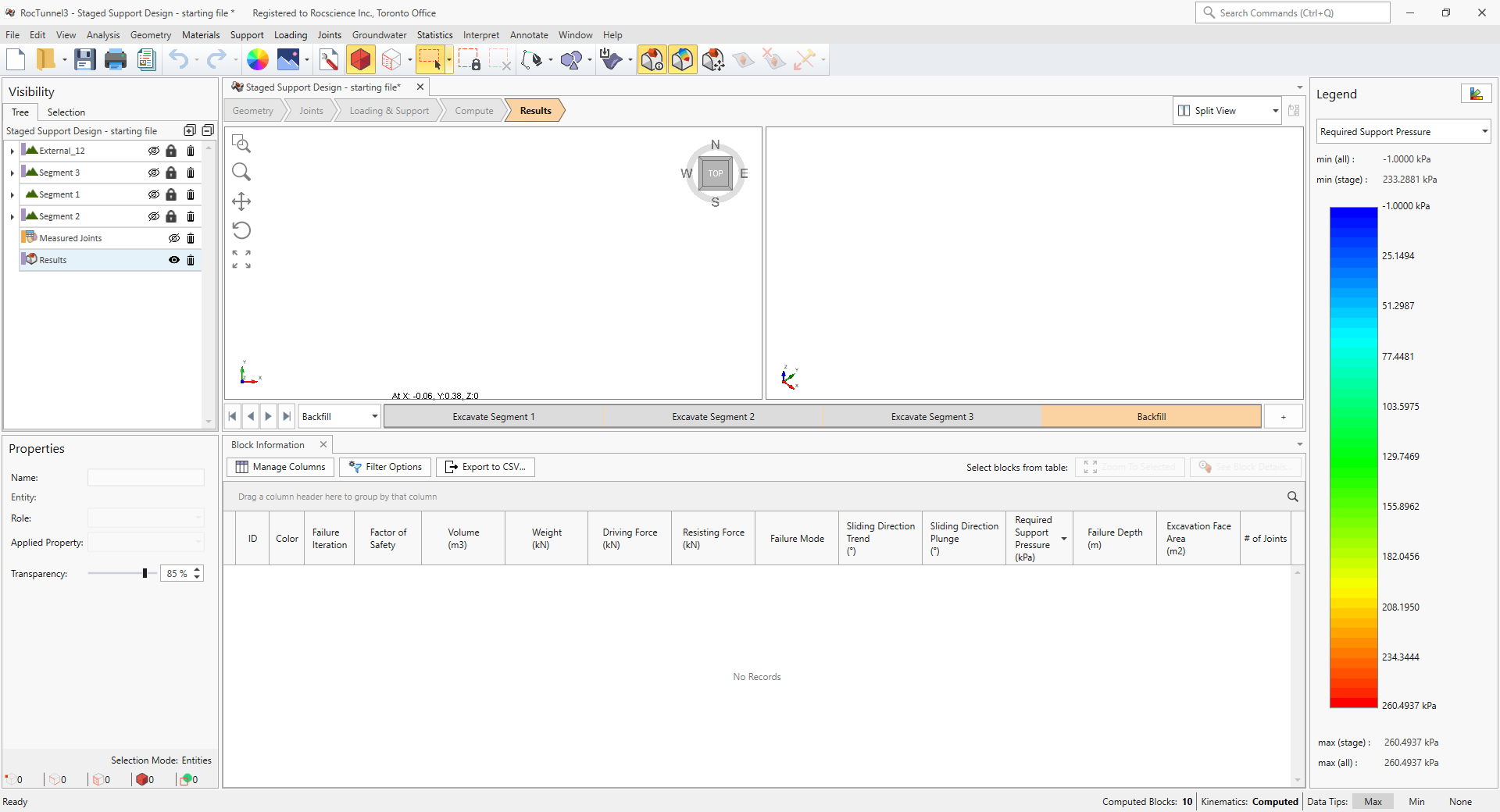
Failed Blocks contoured and sorted by Required Support Pressure in Backfill stage
Note the maximum Required Support Pressure in each stage and where on the excavation they occur.
4.2 Failure Depth
To view block by Failure Depth:
- Left-click the Failure Depth header twice to sort the rows in descending order by Required Support Pressure
- Set the Legend data to Failure Depth.
- Select the Excavate Segment 1 stage from the Stage tabs.

Failed Blocks contoured and sorted by Failure Depth in Excavate Segment 1 stage - Select the Excavate Segment 2 stage from the Stage tabs.
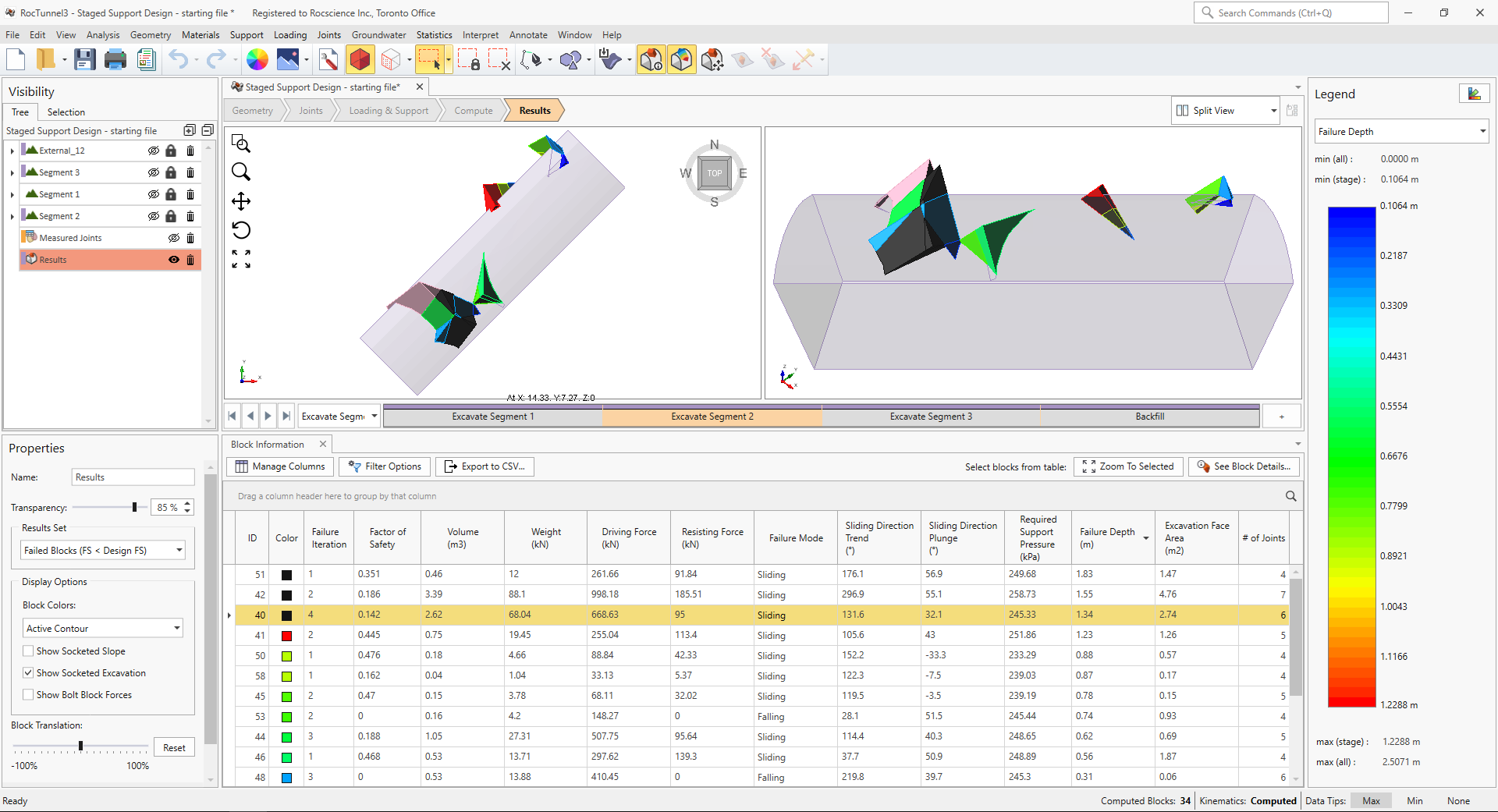
Failed Blocks contoured and sorted by Failure Depth in Excavate Segment 2 stage - Select the Excavate Segment 3 stage from the Stage tabs.
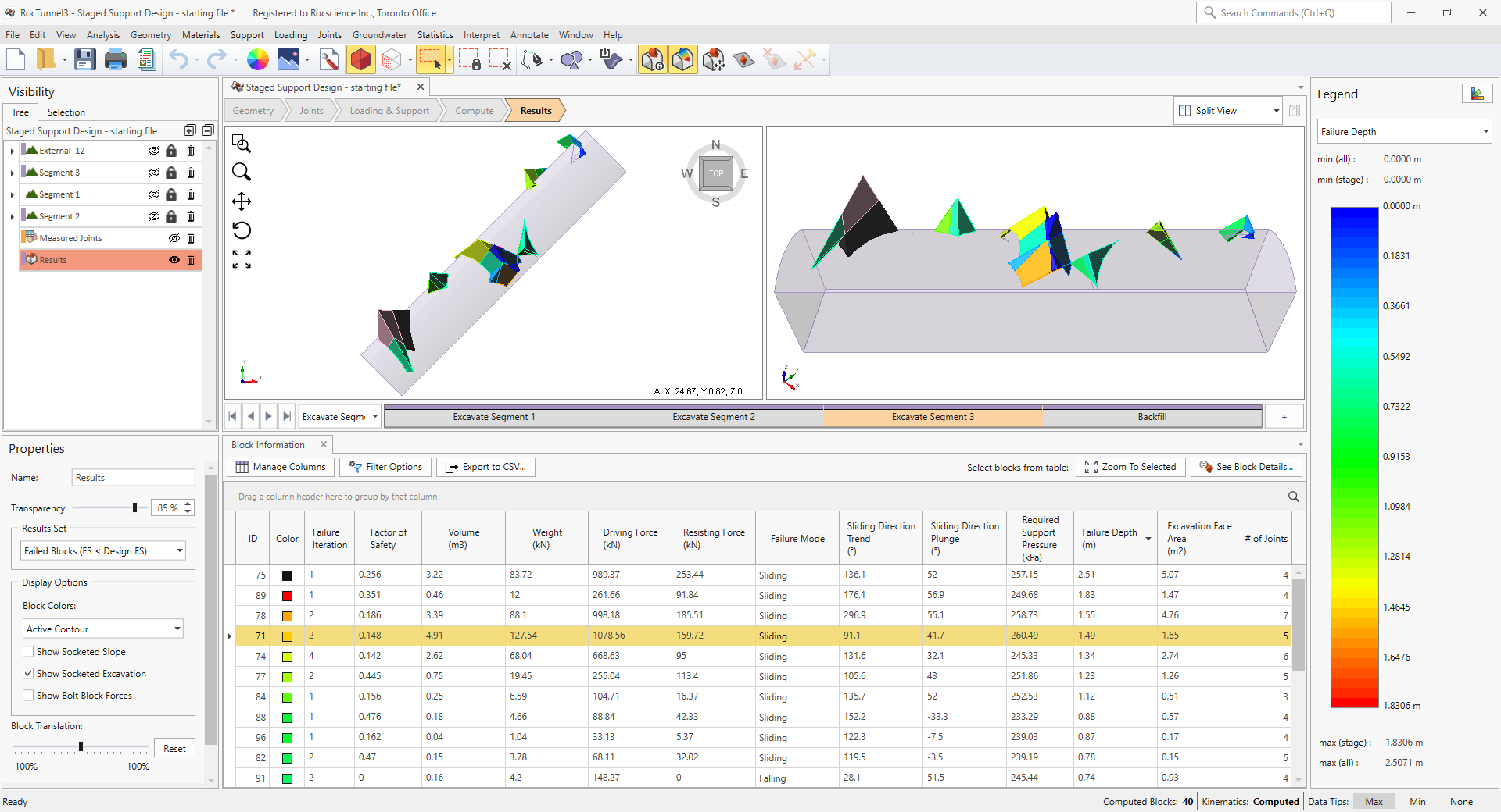
Failed Blocks contoured and sorted by Failure Depth in Excavate Segment 3 stage - Select the Backfill stage from the Stage tabs.
Failed Blocks contoured and sorted by Failure Depth in Backfill stage
Note the maximum Failure Depth across all stages (approx. 2.5 m).
5.0 Staged Support Design
Staged support design takes into account that different blocks may be formed in different locations due to further excavation. As such, each stage will also likely have different support requirements in terms of extent, capacity and length of supports.
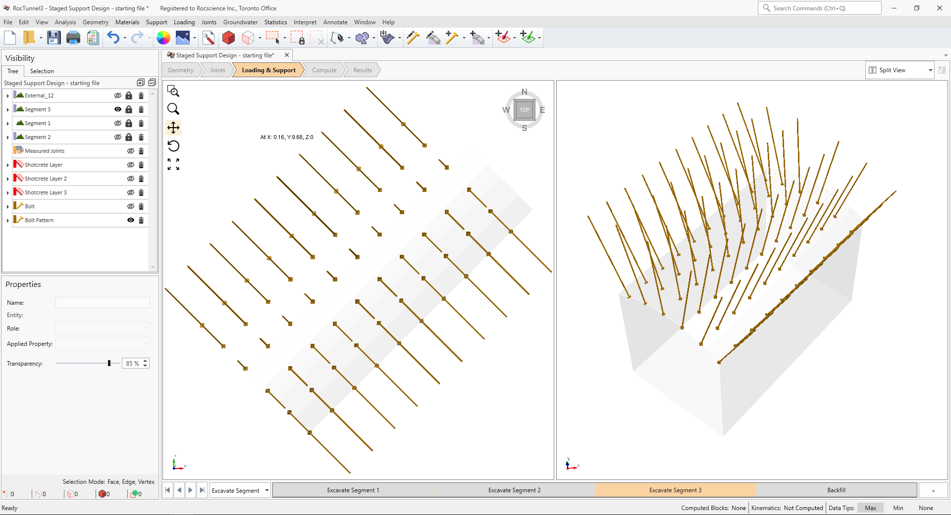
The proposed support system consists of:
- Shotcrete which will provide sufficient support for smaller blocks around the tunnel perimeter (Volume < 1 m3) which will likely not be sufficiently intersected by bolts and also add support capacity for larger blocks.
- Bolt Pattern which will provide the remaining support capacity required by larger blocks around the tunnel perimeter.
- A single Spot Bolt for temporary support of a block on the excavated end of the tunnel of Segment 1.
5.1 Shotcrete Properties
To define Shotcrete Properties:
- Select Support > Define Shotcrete Properties

- In the Define Shotcrete Properties dialog:
- Set Shear Strength = 1000 kPa
- Set Unit Weight = 26 kN/m3
- Set Thickness 0.1 m
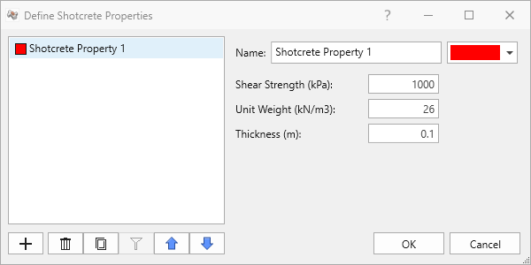
Shotcrete Property 1 in Define Shotcrete Properties dialog - Click OK.
5.2 Staged Shotcrete Application
In Excavate Segment 1 stage, support is required over the roof, southwest end, and northwest wall of Segment 1. For the this tutorial, we will:
- Apply a layer of shotcrete over the roof and walls of Segment 1.
- Install at Excavate Segment 1
- Remove at Never.
- Apply a single spot bolt with at least 0.85 kN capacity (Required Support Pressure x Excavation Face Area = 2.92 kPa x 0.29 m2) to support block 33
- Install at Excavate Segment 1
- Remove at Excavate Segment 2. The opening will be further excavated in Excavate Segment 2 and the unstable block will be removed by the excavation.
To add shotcrete:
- Select Interpret > Clear Results

- Select Excavate Segment 1 stage in Stages tabs.
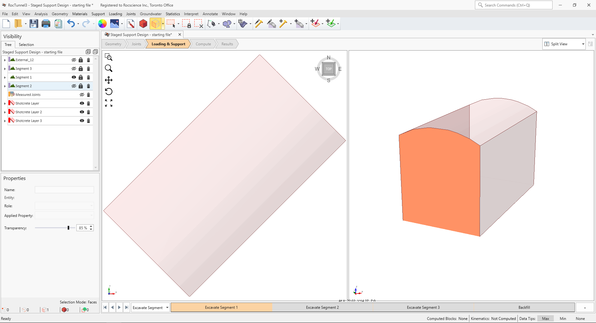
- Ensure Edit > Selection Mode > Faces Selection

- Hold down CTRL key and left-click or lasso (left-click and drag) to select the roof and wall faces of Segment 1 node.
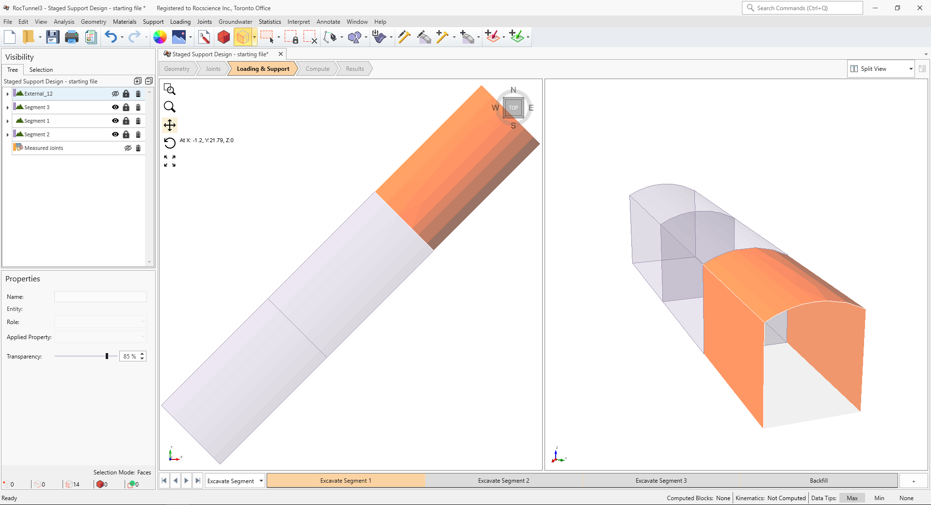
3D CAD View showing Segment 1 faces selection - Select Support > Add Shotcrete to Selected Surface

- In the Add Shotcrete to Selected dialog:
- Set Shotcrete Property = Shotcrete Property 1
- Set Install at Stage = Excavate Segment 1
- Set Remove at Stage = Never
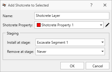
Add Shotcrete to Selected dialog - Select OK.
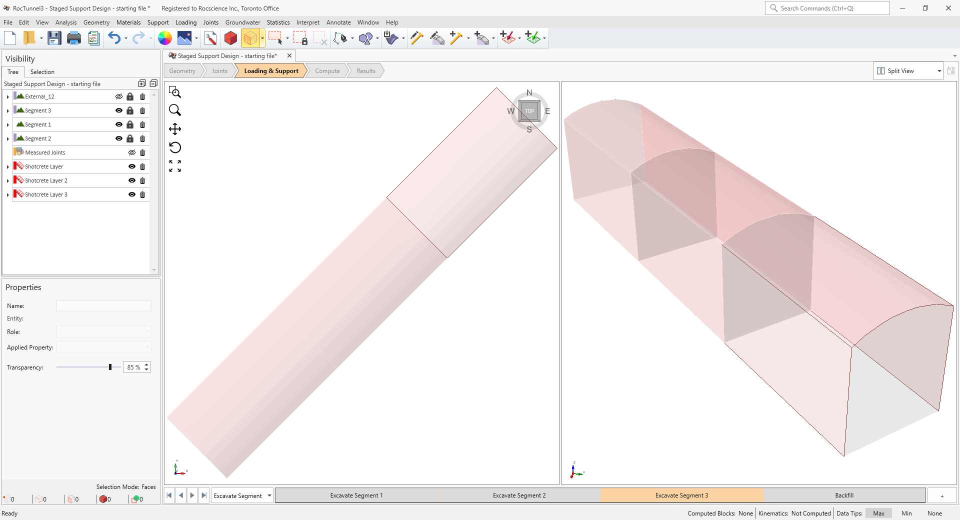
In Excavate Segment 2 stage, support is require over the roof of Segment 2.
- Apply a layer of shotcrete over the roof and walls of Segment 2.
- Install at Excavate Segment 2
- Remove at Never.
To add shotcrete:
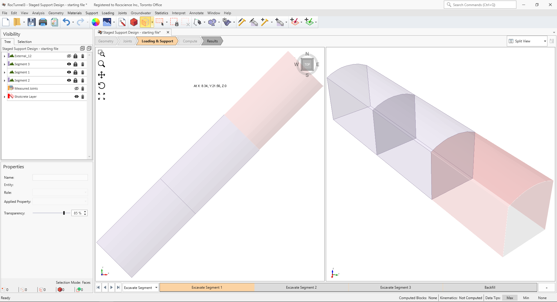
- Select Excavate Segment 2 stage in Stages tabs
- Hold down CTRL key and left-click or lasso (left-click and drag) to select the roof and wall faces of Segment 2 node.
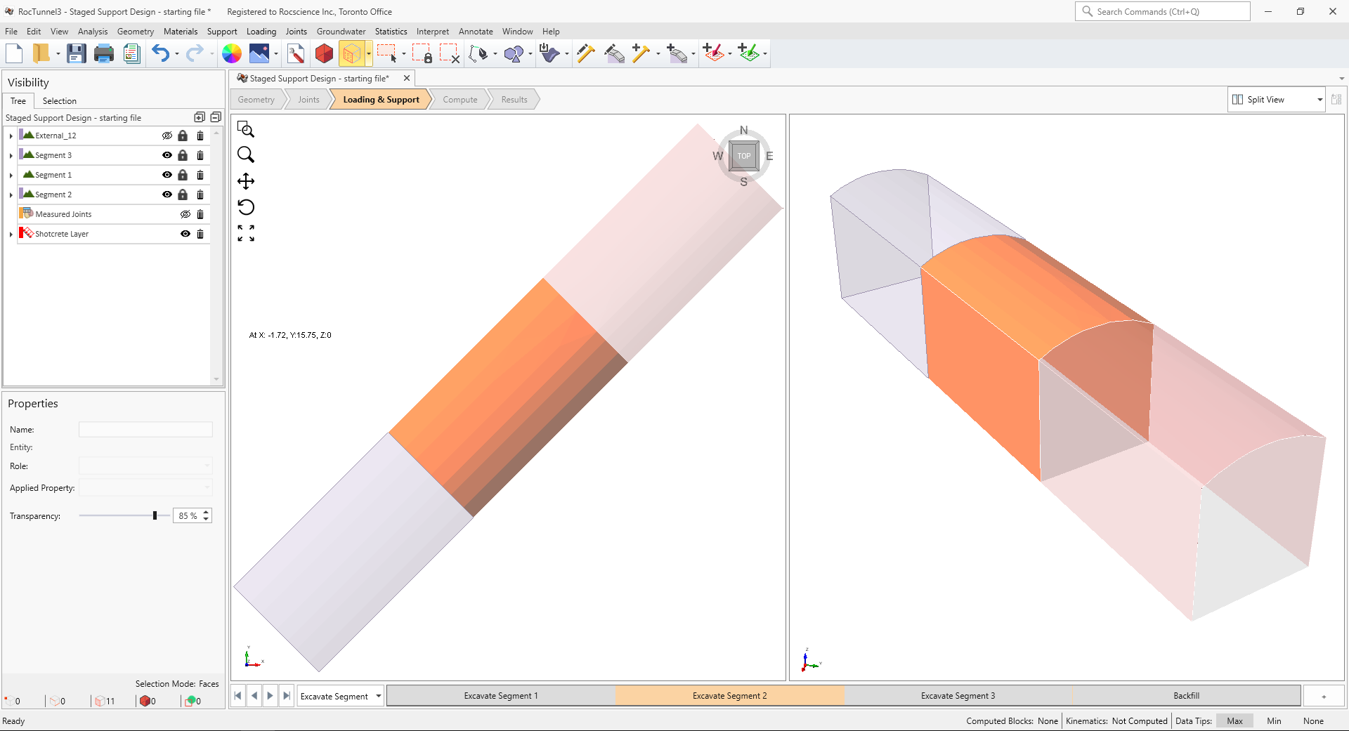
3D CAD View showing Segment 2 faces selection - Select Support > Add Shotcrete to Selected Surface
- In the Add Shotcrete to Selected dialog:
- Set Shotcrete Property = Shotcrete Property 1
- Set Install at Stage = Excavate Segment 2
- Set Remove at Stage = Never
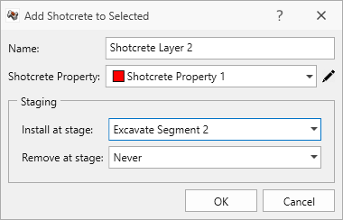
Add Shotcrete to Selected dialog - Select OK.
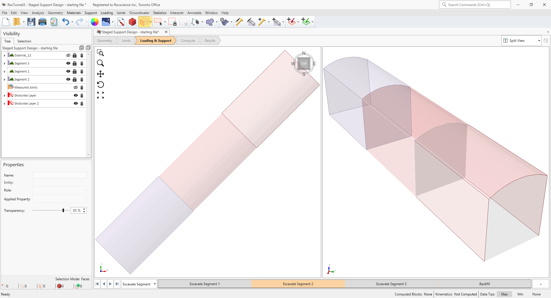
In Excavate Segment 3 stage, support is require over the roof of Segment 3.
- Apply a layer of shotcrete over the roof and walls of Segment 3.
- Install at Excavate Segment 3
- Remove at Never.
To add shotcrete:
- Select Excavate Segment 3 stage in Stages tabs
- Hold down CTRL key and left-click or lasso (left-click and drag) to select the roof and wall faces of Segment 3 node.
3D CAD View showing Segment 3 faces selection - Select Support > Add Shotcrete to Selected Surface
- In the Add Shotcrete to Selected dialog:
- Set Shotcrete Property = Shotcrete Property 1
- Set Install at Stage = Excavate Segment 3
- Set Remove at Stage = Never

Add Shotcrete to Selected dialog - Select OK.
No supports are required for the last Backfill stage.
5.3 Compute (after Shotcrete Application)
To re-compute:
- Select Analysis > Compute Blocks
- Select Analysis > Compute Kinematics
- Ensure Results Set = Failed Blocks (FS < Design FS) under Results node's Properties pane.
- Select Interpret > Block Information
- Select the Excavate Segment 1 stage from the Stage tabs.
Failed Blocks in Excavate Segment 1 stage - Select the Excavate Segment 2 stage from the Stage tabs.
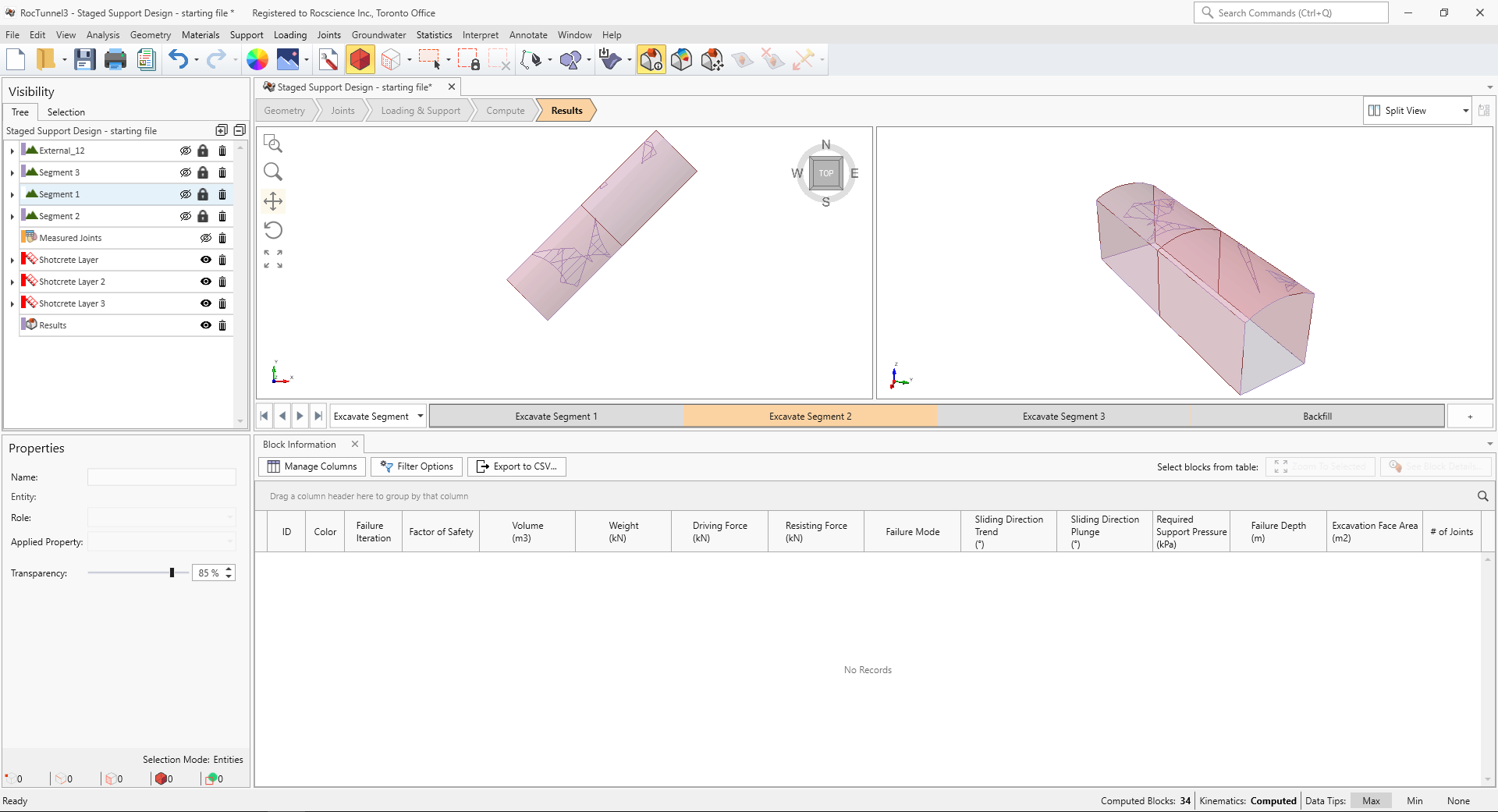
Failed Blocks in Excavate Segment 2 stage - Select the Excavate Segment 3 stage from the Stage tabs.
Failed Blocks in Excavate Segment 3 stage - Select the Backfill stage from the Stage tabs.
Failed Blocks in Backfill stage
Additional supports are required in Excavate Segment 1 and Excavate Segment 3 stages.
5.4 Bolt Properties
To define Bolt Properties:
- Select Support > Define Bolt Properties

- In the Define Bolt Properties dialog:
- Set Support Type = Simple Bolt Force
- Set Force Application = Passive (Method B). Passive force application assumes that the bolt only provides capacity once there is movement.
- Set Force = 250 kN
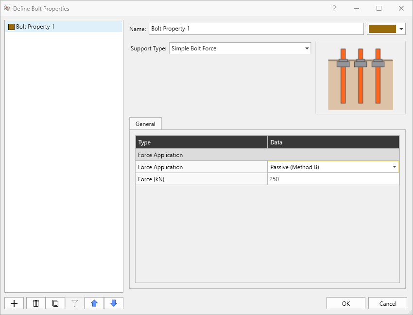
Bolt Property 1 in Define Bolt Properties dialog - Click OK.
5.5 Staged Bolt Application
In the Excavate Segment 1 stage, a spot bolt is required to support Block 33. For this tutorial we will:
- Apply a single spot bolt intersecting Block 33.
- Install at Excavate Segment 1
- Remove at Excavate Segment 2.
Based on the Required Support Pressure (245.1 kPa) and Excavation Face Area (0.29 m2) for Block 3 in Excavate Segment 1 stage, a single spot bolt providing 250 kN (>> 245.1 kPa x 0.29 m2 = 71.1 kPa) should be more than sufficient.
To add a spot bolt:
- Select Interpret > Clear Results
- Select Excavate Segment 1 stage from the Stage tabs
- Ensure only Segment 1 node is visible in the Visibility Tree.
- Ensure Edit > Selection Mode > Faces Selection is selected.
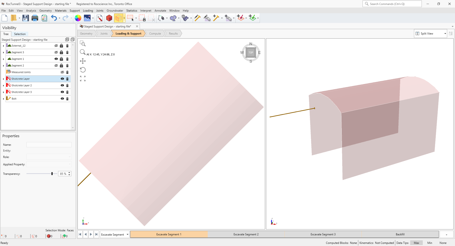
- Left-click on the southwest face of Segment 1 node to select it.
3D CAD View showing Segment 1 face selection - Select Support > Add Bolts to Selected Surface

- In the Add Bolts dialog:
- Set Bolt Property = Bolt Property 1
- Set Orientation = Normal
- Set Flip Orientation = OFF
- Set Length = 4 m. The maximum failure depth is approx. 2.5 m so a bolt length longer than 2.5 m should provide sufficient anchorage.
- Set Install at Stage = Excavate Segment 1
- Set Remove at Stage = Excavate Segment 2
- Set Application = Single Bolt
- Set Bolt Head Location = XYZ and the location as 12.85, 17.55, 1.61
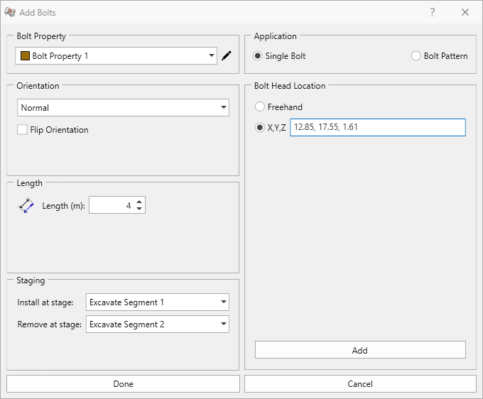
Add Bolts dialog - Click Add button to add the bolt.
- Click Done to exit the dialog.
In Excavate Segment 3 stage, a bolt pattern will be applied to support the blocks on the roof. For this tutorial we will:
- Apply a bolt pattern over the roof of Segment 3.
- Install at Excavate Segment 3
- Remove at Never.
Based on the maximum Required Support Pressure in Excavate Segment 3 stage (173.4 kPa), 250 kN capacity bolts spaced at 1 m by 1 m should provide an average support of 250 kPa which should be sufficient.
To add a bolt pattern:
- Select the Excavate Segment 3 stage from the Stage tabs.
- Ensure only the Segment 3 node is visible in the Visibility Tree.
- Hold down CTRL key and left-click or lasso (left-click and drag) to select the roof faces of Segment 3
node.
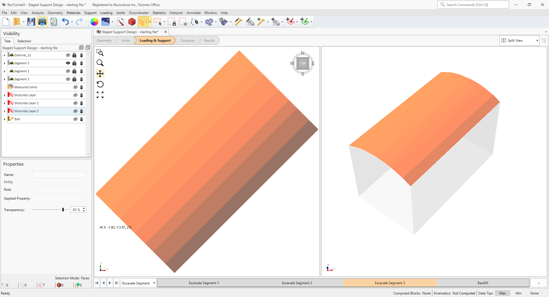
3D CAD View showing Segment 3 face selection - Select Support > Add Bolts to Selected Surface
- In the Add Bolts dialog:
- Set Bolt Property = Bolt Property 1
- Set Orientation = Normal
- Set Flip Orientation = OFF
- Set Length = 4 m. The maximum failure depth is approx. 2.5 m so a bolt length longer than 2.5 m should provide sufficient anchorage.
- Set Install at Stage = Excavate Segment 3
- Set Remove at Stage = Never
- Set Application = Bolt Pattern
- Set Primary Path Start = 1.95, 0.31, 2.51, Primary Path End = 9.02, 7.38, 2.51
- Set Secondary Path = OFF. The bolt pattern is assumed to be rectangular.
- Set Primary Spacing = 1 m
- Set Primary Rows = OFF
- Set Primary Offset = 0 m
- Set Secondary Spacing = 1 m
- Set Secondary Rows = OFF
- Set Secondary Offset = 0 m
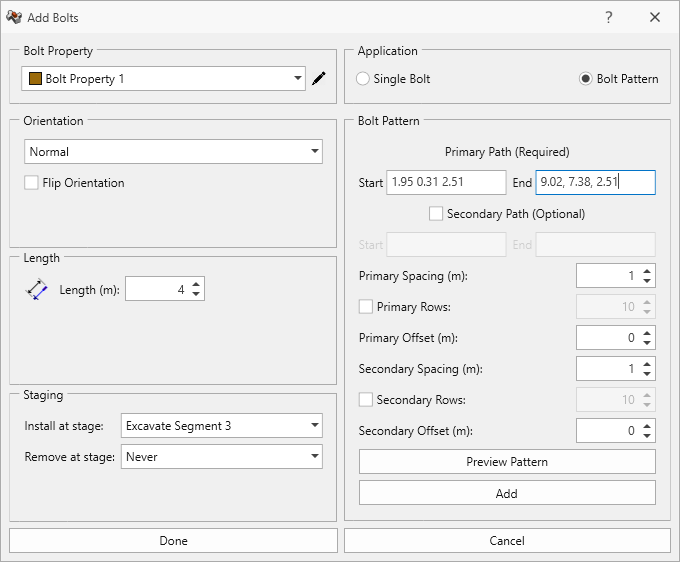
Add Bolts dialog - Click Add button to add the bolt pattern.
- Click Done to exit the dialog.
5.6 Compute (after Bolt Application)
To re-compute:
- Select Analysis > Compute Blocks
- Select Analysis > Compute Kinematics
- Ensure Results Set = Failed Blocks (FS < Design FS) under Results node's Properties pane.
All blocks across all stages meet the Design Factor of Safety threshold after applying a system of shotcrete and bolt supports.
This concludes Tutorial 6.