Graph Liner Data
To graph liner, composite liner, or structural interface data:
- Select Graph Liner Data
 from the toolbar or the Graph menu. You will first be prompted to pick the liner(s) to graph.
 - Liners are selected indirectly, by selecting the boundary entity that they are lining (i.e. excavation, stage, material, or external boundaries). You can select the desired boundaries individually with the left mouse button, or with a selection window, or by using Select All in the right-click menu to select all liners.
- When you are finished selecting, press Enter, or right-click and select Graph Selected from the popup menu.
- You will then see the Graph Liner Data dialog, which allows you to select the data type (see below section) to plot, as well as plotting data from multiple stages on the same plot. You can also choose whether to colour-code the lines according to the liner type (if you are plotting different liner types on the same graph), or according to the stage (if you are plotting data from multiple stages).
- For composite liners or structural interfaces, a Composite/Structural Layer section is available for you to select one or more support layers to plot. See the Select Support Layer topic for more information.
- When you have made the desired selections in this dialog, select Plot and the graph will be generated in RS2. Alternatively, data may be plotted in Excel or copied to the clipboard, by selecting the Plot in Excel or Copy Data buttons. See the Plot in Excel and Copy Data topics for details.
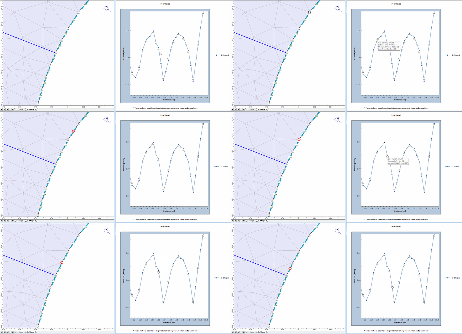
- If you have both the viewport and the graph windows open side-by-side, click on a data point in the graph, the corresponded node will be highlighted with a red circle in your viewport (see GIF below).

Liner result data point highlight.
- If you have both the viewport and the graph windows open side-by-side, click on a data point in the graph, the corresponded node will be highlighted with a red circle in your viewport (see GIF below).
If a Probabilistic Analysis has been computed, the statistical liner data can be plotted using the Graph Statistical Liner Data option from the Statistics menu. See the Graph Statistical Liner Data for more details.
Liner Data Types
In the Graph Liner Data dialog, the liner data type can be selected from:
- Axial Force
- Bending Moment
- Shear Force
- Total Displacement
- Horizontal Displacement
- Vertical Displacement
- Curvature
- Axial Strain
- Temperature
- Temperature is only available when the liner thermal properties are defined in the modeler. The Thermal Analysis must be enabled from the Project Settings menu. Then liner thermal properties can be specified in the Define Liner Properties dialog from the Properties menu.
For axisymmetric analysis, below data types are also available:
- Hoop Axial Force
- Hoop Bending Moment
- Hoop Curvature
- Hoop Axial Strain
The axisymmetric analysis can be enabled in the modeler from the Solver Options page in the Project Settings menu.
For composite liners or structural interfaces, below data types are also available:
- Joint Normal Stress
- Joint Shear Stress
- Joint Normal Displacement
- Joint Shear Displacement
Liner Data Graphs
Note the following about the Liner Data graphs in RS2:
- The DISTANCE axis on liner data graphs corresponds to the distance as measured along the boundary entity(s). If liners are discontinuous along a given boundary, then there will be gaps in the liner data curves corresponding to these discontinuities.
- The ID numbering for liner graphs corresponds to the node numbering (of the finite element mesh) along the lined boundaries. This allows you to associate points on the curves with individual liner elements. The liner ID numbers are automatically displayed for all liners any time that liner data is graphed. To turn OFF the display of the ID numbers after graphing, you can uncheck the Liner Numbers option in the Display Options dialog. Alternatively, a convenient shortcut is to right-click on any lined boundary, and uncheck the Liner Numbers option in the popup menu.
Tips
- A shortcut for graphing liner data, is to right-click on a lined boundary, and select Graph Liner Data from the popup menu. The procedure is then the same as steps 4 and 5 above.
- You may find the Show Values option useful in conjunction with Graph Liner Data, to display liner data directly on the model.