Liner Results Overview
The liner results can be viewed if you have added liners, composite liner, or structural interfaces to your RS2 model. The available liner data types include axial force, bending moment, shear force, displacements and etc. (view the full list here).
You can view the following liner results in RS2 Interpret:
- Graph Liner Data
- Show Yielded Liner Data
- Show Liner Values
- Liner values will be displayed directly in the viewport.
- Select Support Layer
- Used for a Composite Liner or a Structural Interface.
- Support Capacity Plots
- Only available for the Reinforced Concrete liner type.
Liner Results Output
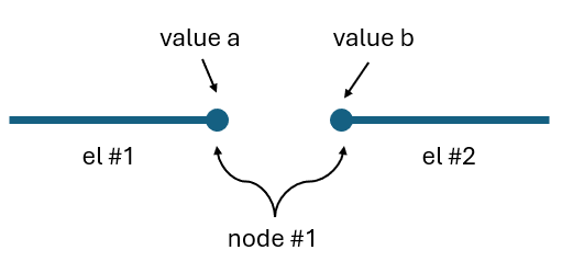
Liner results are outputted at each node of the liner element, with the distribution varying based on mesh element types. For quadratic elements (6- or 8-noded), results are provided at three nodes per liner element side: start, mid-side, and end. For linear elements (3- or 4-noded), results are given at two nodes per liner element side: start and end. See the figure below.
For more information about the Element Type, please see the topic.
For Standard Beam and Reinforced Concrete liner types, if the Beam Element Formulation is Bernoulli, mid-side node results are not provided regardless of the mesh element type. For more information, see the Standard Beam and Reinforced Concrete topic.

Liner Nodal Jump
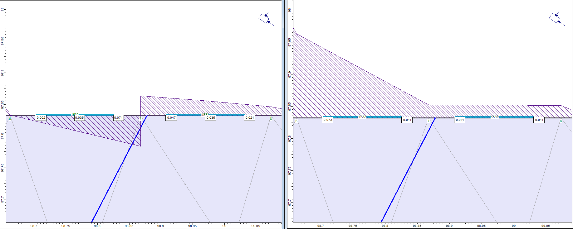
The end node of previous element and the start node of next element represent the same node, but their values can differ. This is referred to as a liner nodal jump between adjacent elements. See Figure 2 below for illustration and Figure 1 above for example.

For linear elements, all liner nodal jumps will be smoothened by applying the averaged values to both sides of the node. The average is calculated as:

For quadratic elements, RS2 tends to smooth out the small liner nodal jumps only. The maximum allowable jump for averaging results can be defined by the Smoothing Limit option in the Display Options dialog. See the Display Options: Liners topic for more information.