Thermal Flow Vectors
The Thermal Flow Vectors  option, available in the toolbar or the Display Options dialog, will draw the thermal flow velocity vectors at each node of the mesh. The Flow Vectors option is only applicable if the Thermal Method = Steady State FEA or Transient FEA in Project Settings.
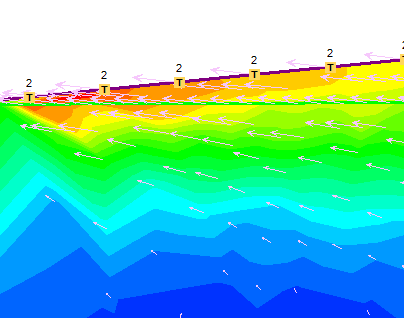
Thermal Flow Vectors and Total Flux contours

The Thermal Flow Vectors indicate the direction of thermal flow, and the relative size of the Thermal Flow Vectors indicates the relative flux of the thermal flow.
Notes:
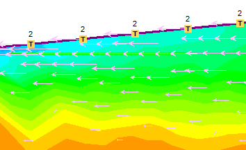
- If you are viewing contours of Horizontal Flux then the Thermal Flow Vectors option will only display the x-component of the total thermal flow vector at each node.
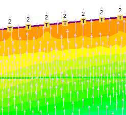
- If you are viewing contours of Vertical Flux then the Thermal Flow Vectors option will only display the y-component of the total thermal flow vector at each node.
- For all other contour plots (e.g. Temperature, Total Conductivity, etc.) the Thermal Flow Vectors option will display the total thermal flow vector at each node.
- If you are viewing differential data , Thermal Flow Vectors will display the differential thermal flow vectors (X, Y or Total, as described above).
Horizontal Thermal Flow Vectors and Horizontal Flux Contours

Vertical Thermal Flow Vectors and Vertical Flux Contours

Size of Thermal Flow Vectors
For display purposes, there are various options for customizing the size of the thermal flow vectors, as displayed on the model. These are useful when you are preparing screen captures.
Increase/Decrease Size
The size of the Thermal Flow Vectors can be increased or decreased by a small increment with the Increase Vector Size or Decrease Vector Size options. These are available in the drop-menu beside the Thermal Flow Vectors toolbar button, or by using the indicated keyboard shortcuts.
Scale Size to All Stages/Visible Stage
For a multi-stage model, this option allows you to choose whether the Thermal Flow Vector size is scaled independently for each stage, or whether a single scale factor is used for all stages (i.e. the scaling takes account of the total range of fluxes over all stages). These options are available in the drop-menu beside the Thermal Flow Vectors toolbar button.
Maximum Size
In the Display Options dialog, you can enter an actual size (mm) for the maximum Thermal Flow Vector. This is the size of the Maximum Thermal Flow Vector as displayed on the screen. All other Thermal Flow Vectors will be scaled accordingly.