Add Thermal Flow Line
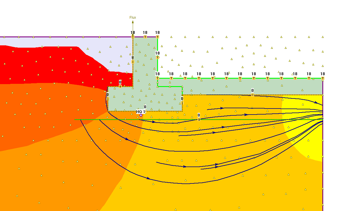
A flow line represents a path of heat flow through the material. Flow occurs in the direction of decreasing Temperature.
Flow lines can be added individually to a model, with the Add Flow Line option, or multiple flow lines can be simultaneously generated with the Add Multiple Thermal Flow Lines option.

To add individual flow lines with the Add Thermal Flow Line option:
- Select Add Thermal Flow Line
 from the toolbar or the Thermal menu.
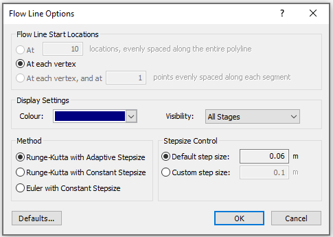
 - You will see a dialog which allows you to configure the following options:
- Colour - you can choose a colour for the Thermal Flow Line
- Visibility - for a multi-stage model, you can choose to display the Thermal Flow Line at All Stages (Visibility = All Stages) or only for the currently viewed stage (Visibility = Only for this Stage)
- Step Size - a Thermal Flow Line is generated by determining the flow direction at a point and traveling an increment of distance in the flow direction, to determine the next point. This process is repeated until the Thermal Flow Line reaches the external boundary. The Default Step Size option will generate the Thermal Flow Line using a default increment of distance between points (equal to 1/100 of the model extents). The Custom Step Size option will generate the Flow Line with a user-defined increment of distance between points.
- You will be prompted to enter a starting location for the Thermal Flow Line. You can do this graphically with the mouse, or enter an x,y coordinate pair in the prompt line.
- Enter the starting point, and the Thermal Flow Line will be generated. An arrow symbol on the Thermal Flow Line will indicate the direction of flow.

- From the starting point you have entered, the Thermal Flow Line is always generated in the direction of flow (i.e. in the direction of decreasing Temperature). Therefore, in general, you will probably want to enter a starting location which is at a high Temperature value (i.e. usually at one edge of the External boundary). You may therefore want to view Temperature contours while you are adding thermal flow lines, although you can add thermal flow lines while viewing any contoured data.
- You can add as many thermal flow lines as you wish, by repeating Step 4.
- When you are finished adding thermal flow lines, press Escape, or right click and select Cancel to exit the Add Thermal Flow Line option.