Thermal Analysis
To begin thermal modelling in RS2 you must first do the following:
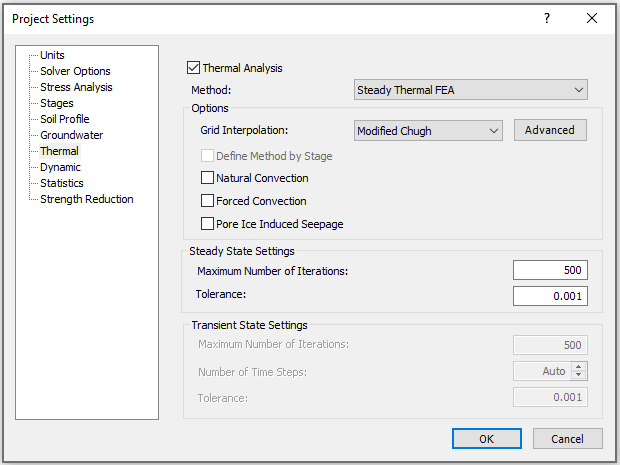
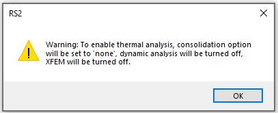
- In the Project Settings dialog, select the Thermal page from the list, and select the Thermal Analysis checkbox (see the image below for default settings).
- Choose a Thermal Analysis Method.
- If Static Temperature or Steady State Thermal FEA is chosen, proceed to step 4.
- If Transient Thermal FEA is chosen, specify whether the method will be different by stage. If so, select the checkbox for the Define Method by Stage option. Proceed to Step 3.
- Select the Stages page in Project Settings dialog (for the Transient Thermal FEA method only).
- When the Define Method by Stage option is unchecked, the number of stages, stage name, and time need to be specified.
- When the Define Method by Stage option is checked, the number of stages, stage name, time, and stage thermal method need to be specified.
- Set up the rest of parameters under the Thermal page (see below for details).
After enabling the Thermal Analysis, you can define thermal properties for materials and supports, add temperature grid, add heat transfer section, and apply thermal boundary conditions.


Thermal Analysis Methods
- Static Temperature: there is no temperature change or heat transfer, the model stays at its initial temperature.
- Steady Thermal FEA: a finite element analysis will be performed for heat transfer in steady state.
- Transient Thermal FEA: a finite element analysis will be performed for heat transfer in transient state, and time step will be accounted for. The time for each stage is required to specify in the Stages page in Project Settings dialog.
See the RS2 Thermal Analysis Theory Manual for theories and equations of thermal analysis methods.
Options
Grid Interpolation
Under any thermal analysis method, a grid interpolation method must be specified. The Interpolation Method is used to calculate the temperature at any point in the soil or rock, from the values at the grid points. There are several different Interpolation Methods available in RS2. See the shared Interpolation Method page under Groundwater for details).
Advanced
The Advanced option provides Advanced Thermal Settings. A number of criterions used in thermal calculations are constant values. By default, the Thermal Constant are set to Constant. It means each of these criterions stays as a constant value throughout the analysis. When Thermal Constant is set to Temperature Dependent, the criterion values vary during the analysis, they are calculated by the current temperature. The thermal constant criterions include: water density, ice density, air conductivity, and specific heat capacity of air.
Define Method by Stage
The Define Method by Stage option allows you to customize thermal analysis method by stage. It is available for the Transient Thermal FEA method only. When this option is enabled, users should then proceed to the Stages tab in Project Settings dialog to select the thermal method for each stage.
Natural Convection
The Natural Convection option allows you to account for the heat convection induced due to the temperature difference and driven by buoyancy force.
Forced Convection
The Forced Convection option allows you to account for the heat convection caused by hydraulic head differences.
Pore Ice Induced Seepage
The Pore Ice Induced Seepage effect will be accounted for when the option is enabled. The additional suction on top of the existing pore pressure due to a temperature change will be included. The pore ice induced seepage only affects the hydraulic models that have unsaturated behaviors (i.e. Brooks and Corey, Fredlund and Xing, Gardner, Simple, van Genuchten, or user defined). See the Define Hydraulic (Seepage Analysis) topic for unsaturated behaviors.
See the Thermal Analysis Theory Manual for more information about the Natural Convection, Forced Convection and Pore Ice Induced Seepage options.
Steady State Settings
The following parameters can be defined when the Steady Thermal FEA is in use:
Maximum Number of Iterations
This option controls the Maximum Number of Iterations allowed to achieve convergence within the specified Tolerance for steady thermal finite element analysis. If the Tolerance is not achieved within the Maximum Number of Iterations, then the analysis will be terminated at the Maximum Number of Iterations. The default value is 500.
Tolerance
The Tolerance represents the convergence criterion for the steady thermal finite element analysis. The solution is considered acceptable, when the difference in temperature between iterations, at all nodes of the mesh, is less than the Tolerance.
Transient State Settings
The following parameters can be defined when the Transient Thermal FEA is in use:
Maximum Number of Iterations
This option controls the Maximum Number of Iterations allowed to achieve convergence within the specified Tolerance in each time step. If the Tolerance is not achieved within the Maximum Number of Iterations, then the analysis will be terminated at the Maximum Number of Iterations. The default value is 500.
Tolerance
The Tolerance value defines the point at which the finite element solution is considered to have converged. The Tolerance for the transient thermal analysis is a dimensionless parameter which represents the allowable unbalanced temperature in the system, and corresponds to the Convergence Criterion (Absolute Energy or Square Root Energy). For a given Time Step:
- If the energy imbalance of a current state (iteration) is less than the Tolerance value, then the solution is considered to have converged, and the iterations are stopped.
- If the Tolerance value is not achieved within the specified Maximum Number of Iterations (i.e. energy imbalance remains greater than the Tolerance value), then the solution process is deemed not to have converged, for the specified convergence parameters.
For more information about Tolerance and convergence, see the Convergence Criteria document in the RS2 theory section.
The default Tolerance is .001. The suggested range of values is .01 to .001. If your model is experiencing convergence problems, you can try increasing the Tolerance value in order to achieve convergence. However you must be aware that there can be many reasons why a model is not converging (often related to incorrect modeling procedures or input parameters), and increasing the Tolerance will not necessarily give you a correct answer, if your model is incorrect. Larger Tolerance values (e.g. .01) will speed up the solution time, but may give a less accurate solution. Smaller values (e.g. .0001) may give a more accurate solution, however, this will vary depending on the problem, and will increase computation time.
Number of Time Steps
The Number of Time Steps used by Compute at each stage can either be set to Auto or a user-defined value. By default, this setting is on Auto.
- Auto: The number of time step is determined by RS2, and will not necessarily be the same at each stage. Users can specify the minimum and maximum number of time steps with the Min Time Step and Max Time Step options.
- User-defined: The entered number will be used AT EACH STAGE of calculation.