Wick Drains
1.0 Introduction
This tutorial introduces the addition of a wick pattern drainage system to a road embankment. The drains will be installed in Stage 2 and removed in Stage 12. Results will then be analyzed using RS2 Interpret and compared to results from an embankment constructed without wick drains. Finally, a vacuum will be added to the model with wick drains to further increase the rate of consolidation and settlement of the embankment.

2.0 Constructing the Model
Select: File > Recent Folders > Tutorial Folder and select the Wick Drains (Initial) file
2.1 Uncoupled Consolidation
This model is run using the new Uncoupled Consolidation option found in RS2 2019. This option greatly increases the speed of analysis. To set the Consolidation Option:
 Select: Analysis > Project Settings
Under the General tab, set the Consolidation Option to Uncoupled.
2.2 Loading

Because the top of the model represents the true ground surface, the model should use a gravity field stress.
 Select: Loading > Field Stress
Select Gravity as the Field Stress Type. Select the boxes for Use actual ground surface and Use effective stress ratio. Set the Effective Stress Ratio (vertical in and out-of-plane) to 0.5.

2.3 Mesh
![]()
 Select: Mesh > Mesh Setup
Select Mesh Type = Uniform, Element Type = 6 Noded Triangles, and Approximate Number of Elements = 10,000.

Click the Discretize button, followed by the Mesh button. Click OK to close the Mesh Setup dialog. The model should appear as follows after meshing:

2.4 Adding the Wick Drain
![]()
Select: Stage 2. The wick drains will be installed at this stage.
Select: Groundwater > Add Wick Drain Pattern
Enter the following parameters:
- Angle from Horizontal: -90
- Install at Stage: 2
- Remove at Stage: 12
- Diameter: 0.1
- Pressure: 0
- Equivalent Permeability: 0.005
- Drain Length: 10
- In-Plane Spacing: 2

Click to select a point on the ground surface, below where the embankment will be filled. Drag along the ground surface to apply the wick drain pattern to this boundary. Click once more to apply the wick drain pattern, as shown below:

2.5 Groundwater Boundary Conditions
![]()
 Select: Groundwater > Set Boundary Conditions
Follow the steps below to input the transient condition:
- Ensure the Stage 1 tab is selected. From the BC Type drop-down menu, select Total Head (H).
- Enter a Total Head Value (m) of -12 meters.
- Apply the Total Head boundary condition to the side faces of the external boundary:

Click "Apply". From the BC Type drop-down menu, select Unknown (P=0 or Q=0).
Select the segments representing the ground surface:

Click "Apply". The model should now display the following groundwater boundary conditions:

As the embankment is constructed, the unknown boundary condition must be shifted such that the topmost layer of the embankment is the layer with the unknown boundary condition. For example, for Stage 3, the unknown boundary condition will be shifted to the top of the newly added section of the embankment. This also involves using the delete function in the Boundary Conditions dialog to remove the previous unknown boundary condition from the section, before adding the condition to the new top-most portion of the embankment:

Stage 4 will have the same groundwater boundary conditions as Stage 3.
The groundwater boundary conditions for Stage 5 and 6 will be:

The groundwater boundary conditions for Stage 7 and 8 will be:

The groundwater boundary conditions for Stage 9 through 14 will be:

The model construction is now complete.
![]() Select: File > Save As to save the model as Wick Drains (Final)_With Wick.fez
Select: File > Save As to save the model as Wick Drains (Final)_With Wick.fez
 Select: Analysis > Compute
3.0 Results
![]() Select: Analysis > Interpret
Select: Analysis > Interpret
Select: Solid Displacement > Vertical Displacement from the drop-down menu.
4.0 Comparing Embankment with Wick Drains to Without Wick Drains
Without closing Interpret, switch back to the RS2 Modeler.
Navigate to File > Recent Folders > Tutorial Folder and select the No Wick Drains (Final)_No Wick.fez file
![]() Select: Analysis > Compute
Select: Analysis > Compute
![]() Select: Analysis > Interpret
Select: Analysis > Interpret
Vertical Displacement
Select: Solid Displacement > Vertical Displacement from the drop-down menu.
 Select: Window > Tile Vertically to view the results of the embankment model with and without the wick drain pattern simultaneously. Select Stage 9 in both windows.
On each model, add a material query to the embankment surface:
 Select: Query > Add Material Query
Select the top of the embankment by clicking the top left corner and dragging across, then selecting the top right corner. Press Enter.

Select "At each vertex" in the Specify Query Locations dialog. Press OK to close the dialog. A black line will appear along the surface of the embankment, as well as two query values, indicating that the query has been created.

Select the Stage 9 tab in both windows to compare the vertical displacement results after the construction of the embankment.
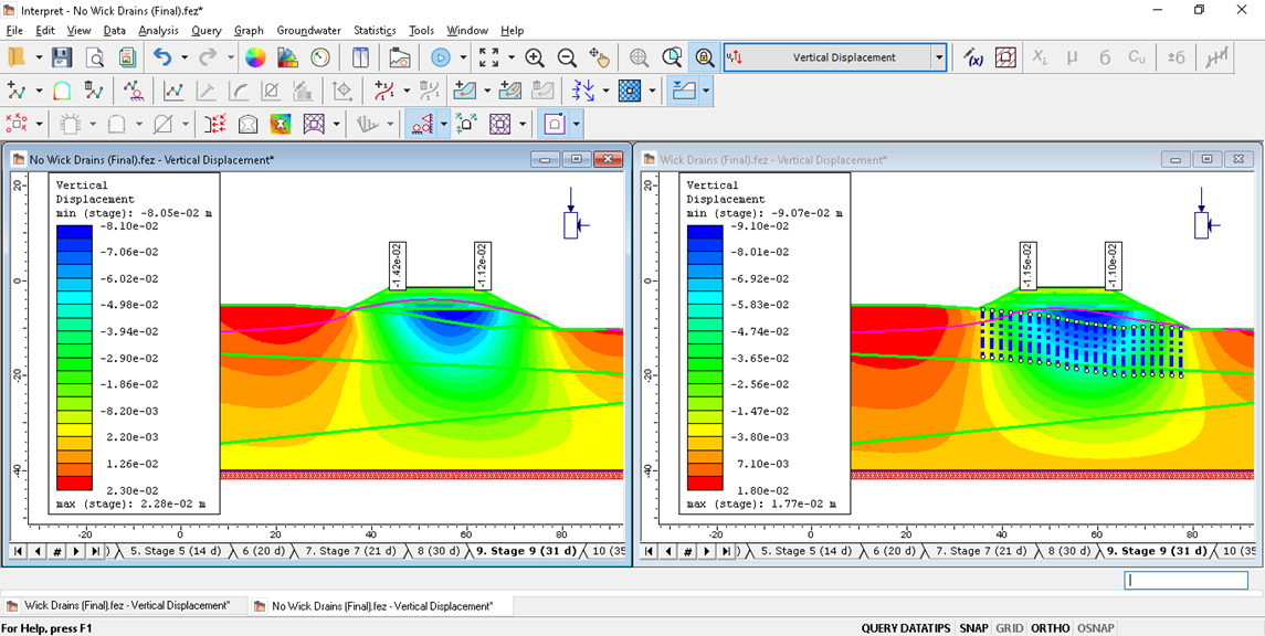
At Stage 9, the stage representing the completion of the embankment construction, the vertical displacement values for both models are similar. Clicking through the stages shows that the addition of the wick drain pattern is successfully speeding up the rate of settlement.
Stage 11:
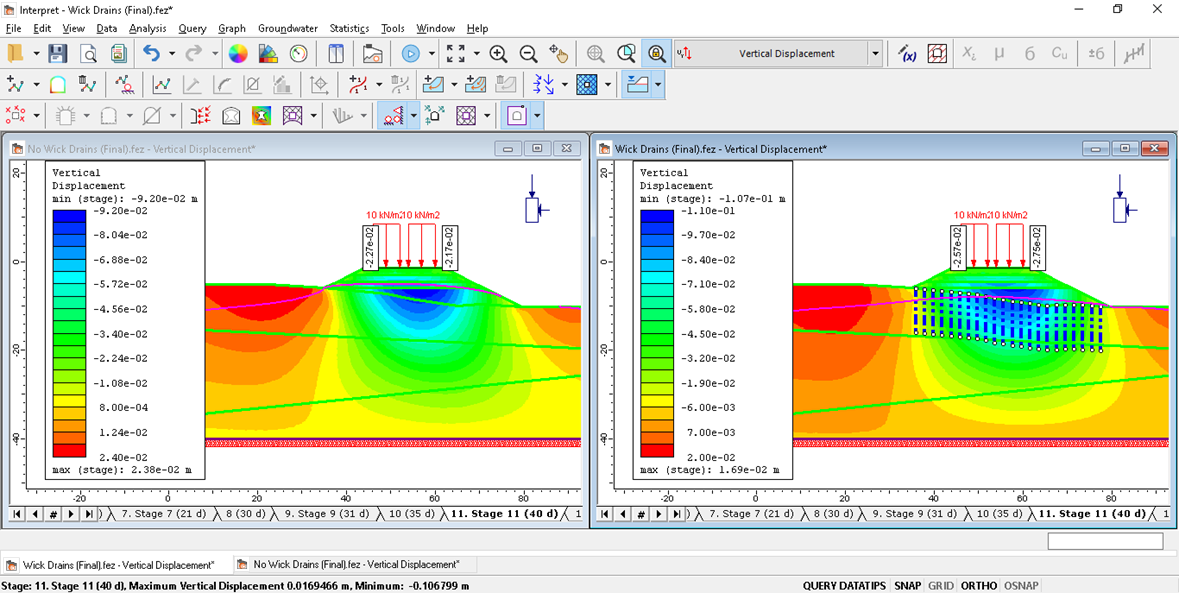
To view the results graphically, we must graph the queries for each model:
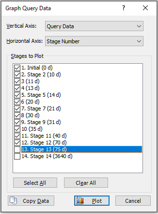
Right-click on the query and select Graph Data. In the Graph Query Data dialog, set the Horizontal Axis to Stage Number and select all stages except 13 and 14. Do this for both models.
 Select: Window > Tile Vertically to view both models and their respective query graphs
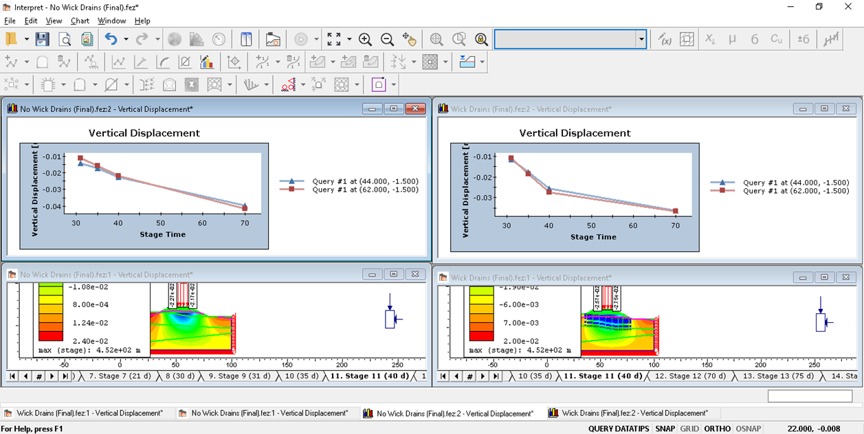
It is evident from the graphs above that adding wick drains to the model significantly increases the rate of consolidation.
Pore Pressure
Select: Seepage > Pore Pressure from the drop-down menu for both models
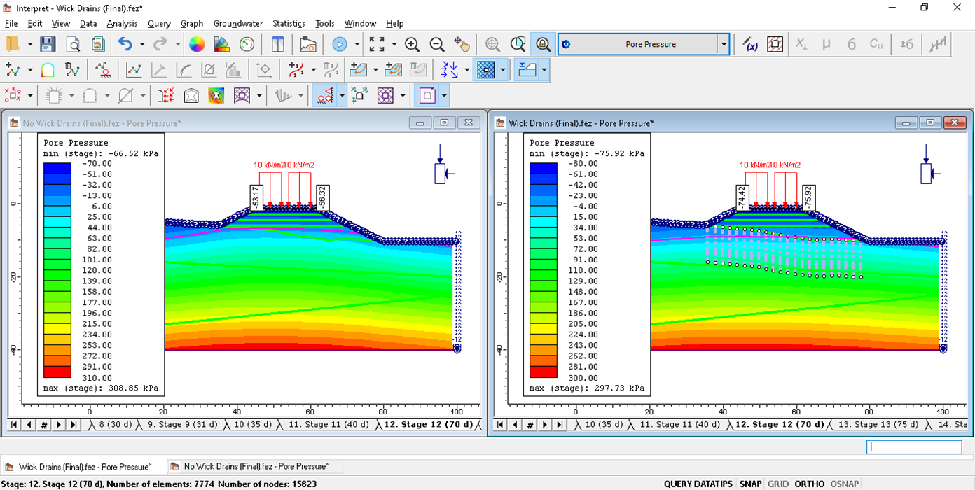
Clicking through stages 9 through 12 shows that there is faster dissipation of pore pressure when wick drains are installed.
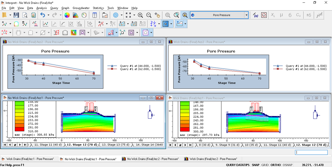
Again, graphing both queries provides a graphical representation of the increase in the rate of pore pressure dissipation resulting from the addition of wick drains.
5.0 Adding Vacuum
RS2 2019 allows users to define the P-value or vacuum when setting Unknown Boundary Conditions. The vacuum will be applied to the boundary at the base of the embankment for this model. The vacuum will be added at Stage 9 (when the embankment construction is complete) and removed at Stage 10.
Without closing Interpret, switch back to the RS2 Modeller.
Navigate to File > Recent Folders > Tutorial Folder and select the Wick Drains (Vacuum Initial) file
In this file, we will redefine the groundwater boundary conditions to specify a vacuum boundary condition at the base of the embankment for Stages 9 and 10.
Select: Groundwater Workflow Tab
Select: Groundwater > Set Boundary Conditions and select Unknown (P=0 or Q=0).
Check the box for Vacuum Pressure and set the value to -70. Also, check the box to Apply at this stage only (do not propagate).
Select the ground segment representing the base of the embankment at Stages 9 and hit Apply. Repeat for stage 10. The model should look as follows:

Save the model as Wick Drains (Final)_Wick and Vacuum.fez
![]() Select: Analysis > Compute
Select: Analysis > Compute
Vertical Displacement
Select: Solid Displacement > Vertical Displacement from the drop down menu.
Stage 11:
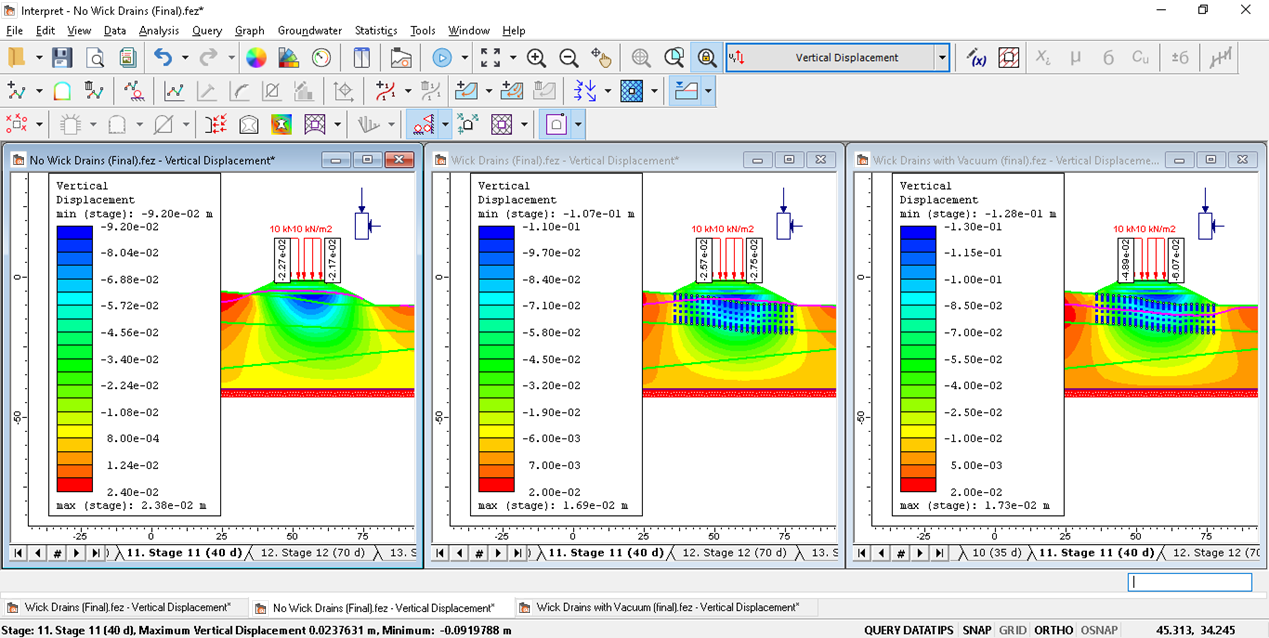
Plotting the same query data from the top of the embankment allows for comparison of the rate of vertical displacement for the three models:
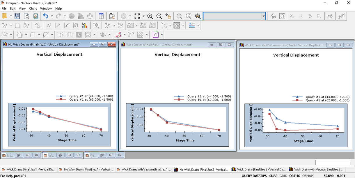
It is evident from the plots of the vertical displacement query that adding a vacuum to the base of the embankment when the wick drain is present further increases the rate of settlement of the soil.
This concludes the Wick Drain tutorial.