Beams and Piles Results Overview
The mechanical behaviour of beams and piles installed in a model becomes available after completing the stress analysis. Once the engine completes computing the stress analysis, beam and pile result entity becomes generated (when switched to Results tab).
To view results of beams and piles:
- Compute stress analysis and open Results tab.
- From the Legend pane on the right-hand side of the viewport, select Result type = Beams & Piles; and
- Select data type to display from the dropdown menu below.

A global frame system is respected to compute/display beam and pile results. In general, the following data types are displayed for both beams and piles:
- Beam X Displacement
- Beam Y Displacement
- Beam Z Displacement
- Beam Total Displacement
- Axial Force
- Shear Force (Min Axis)
- Shear Force (Max Axis)
- Moment (Min Axis)
- Moment (Max Axis)
For piles, which have interface properties defined, following data types are additionally computed:
- X Displacement (at pile interface)
- Y Displacement (at pile interface)
- Z Displacement (at pile interface)
- Total Displacement (at pile interface)
- Interface Shear Force
- Interface Normal Force (Min Axis)
- Interface Normal Force (Max Axis)
- Confining Stress
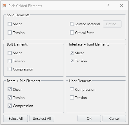
The mode of failure and the failure location can be displayed on beam or pile result entities by selecting the failure mode from Interpret > Yielded Element > Pick Yielded Elements. In RS3, failure of beam and pile elements may occur in three different modes: shear, tension and compression. Unlike tension and compression failure modes, which are treated as the failure of beam itself, shear failure refers to the failure at the interface for pile elements when the shear stress induced at the pile interface exceeds its interface shear strength.

Result Display
Beam and Pile result entities can be selected-deselected from the Viewports or Visibility Pane. When a Pile pattern result entity is selected from the visibility tree all the child piles consisting of that pattern will be selected. It is possible to hide or unhide the visuals of those entities by clicking the Eye icon.
The properties pane for single beam or pile results has several data visualization functionalities, including Show Sample Value (displaying numerical value at the nodes of beam or pile nodes for the data plot selected from the legend), Show Sample Positions (displaying geometric location of the nodes of beam or pile), and Graph Data (plotting available data in x-y coordinate system on a new viewport tab).
Beam Properties Pane
The beam properties pane includes additional data visualization functionalities. The Show Deformation checkbox allows the user to display the deformed configuration of the beam entity. The scale of deformed shape exaggeration can be adjusted using the scaling options, such as Global scaling and Scale Factor (see here for details). The Show Contour checkbox allows the user to map the selected contour onto the beam entity.
Pile Pattern Properties Pane
The pile pattern properties pane is not different from single beam or pile properties pane, other than the additional controls over selecting/deselecting the result entities of its component. This means that under the properties pane, list of piles constituting that pattern is displayed and each individual can be selected. The selected individual or multiple (by holding Ctrl/Shift button) result entities become highlighted on the visibility pane. When components are selected, changes made to the data visualization functionalities like Show Sample Value, Show Sample Positions, and Graph Data will only be applied to those selected. Also, the visibility of individual components can be controlled by clicking the Eye icon.
When a large number of beams and piles with different types and installation/removal stage are used in the model, it could become cumbersome process to manually track and select the beams and piles that are of interest. In this case, Advanced Beams and Piles Selection can be a useful tool that provides a table of all beams and piles used in the model and allows user to glance through, sort and filter.