Mesh Planes
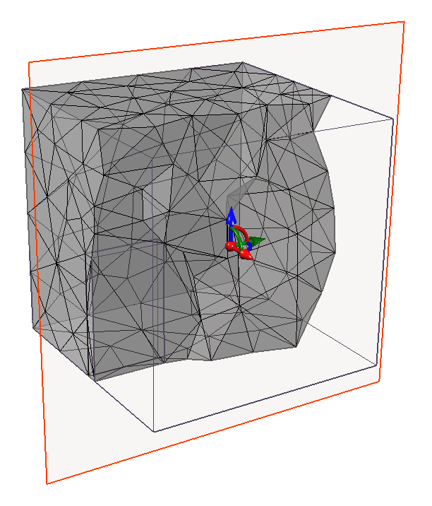
The Mesh Plane  option allows you to view cross-sections of the current mesh, evaluating the mesh quality visually. This option is for display purpose only; no change will be made to the model. To use it:
- Select the Mesh workflow tab

- Ensure a mesh has already been generated in the model.
If not, select Mesh > Mesh Settings option to define and generate a mesh, or select the Mesh > Mesh
  option from the menu to directly generate a mesh. See the Mesh Generation topic for more details.
 - Select one of the Mesh Plane XY
 , YZ
, YZ  or ZX
or ZX  options in the Mesh Plane sub-menu of the Mesh menu, or from the toolbar.
 - Use the Freehand Manipulation
 options on the plane to graphically translate or rotate your plane. Hover over any arrow in the icon. Once it is highlighted, you can drag your mouse in the arrow direction to apply a translation on the entities. You can also apply a translation by selecting the ball in the icon and dragging your mouse. You can also hover over any curved line to apply a rotation about the respective axis.
 - When done, right-click and select Update to regenerate the viewed section of the mesh.
You can see the 3D mesh across the cross-section. See the example Figure below. - You can right-click and select Reflect to view the mesh on the flipped side.
- When finish viewing, exit the mesh plane view by right-click and select Done
 , or from the Mesh Plane sub-menu of the Mesh menu.
To further detect the poor-quality elements, please proceed to the Mesh Quality  option. See the Mesh Quality topic for more details.
