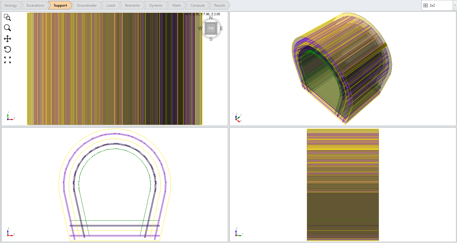
Define Lining Composition
The Define Lining Composition option allows you to define multiple lining sets. Each lining set can be comprised of one or multiple liner layers, a liner layer might include joint interfaces. Single or composite liners can be created:
- For single liners, only one liner layer is included in a lining set.
- For composite liners (multi-layer liners), one or more liner layers can be included. Joints may be incorporated as sliding interfaces on top or below a liner layer, or between two adjacent liner layers.
The order and staging of each layer can be customized. This option is used after the Define Liner Properties option and before the Add Lining option.
Define Lining Composition
Follow the steps to define lining sets:
- Select the Support workflow tab

- Select Define Lining Composition
 from the toolbar or the Liners
  sub-menu of the Support menu.
TIP: you can also right-click on the viewing window and select Define Lining Composition from the menu.
You will see the Lining Composition dialog with a list of currently defined lining sets at the left of the dialog.
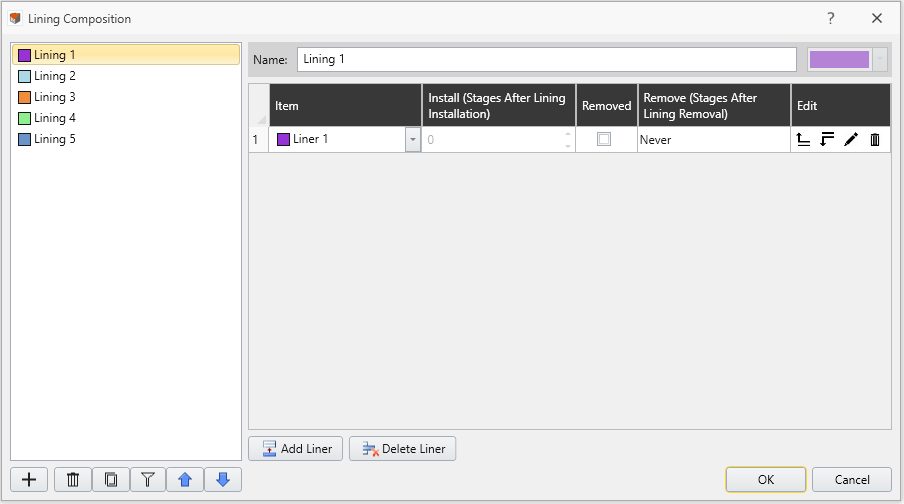
Lining Set
- To create a new lining set, select the Add
 button, or choose an existing lining set from the list at the left of the dialog.
Liner Layer
- Within a lining set, select the Add Layer
 button to add a liner layer. To delete a layer, select the Delete Layer
  button.
 - For a liner layer, use the dropdown menu to select a defined liner. Select the grey pencil icon
 in the Edit section to edit the liner for that layer. Select the Delete
  button to delete the layer.
Liner Interface
- To add a liner interface to a liner layer, select the arrow up
 or arrow down
  icon in edit section. A joint will be added as a liner interface to either above or below the liner respectively.
 - Use the dropdown menu to select a defined joint. Select the grey pencil icon
 in the Edit section to modify the joint properties for that layer. Select the Delete
  button to delete the interface.
- Only one interface can be added between two liner layers, it can be added either below the upper liner layer (with the arrow down
 icon), or above the lower liner layer (with the arrow up icon
  ).
). - Figure below shows three liner interfaces applied to a lining set: above Liner 1, between Liner 1 and 2, and below Liner 2. Respective arrows are highlighted.
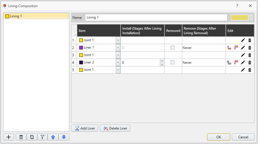
- Only one interface can be added between two liner layers, it can be added either below the upper liner layer (with the arrow down
- Change the Installation and Removal stages for any layer. Ensure to check the Removed checkbox to enable layer removal. Entered stage values are relative to the installation of the lining set. This allows more flexibility to reuse the same lining set for multiple stages of your model.
- Repeat steps 3 to 8 as required to define different lining sets and their liner layers.
- Press OK when you are done defining the lining sets.
Order of Liner Layers
The order of liner layers is important for defining the side of the selected face(s) that a liner layer should appear. For example, you want to apply shotcrete to an excavation wall. In this case, if you want to consider sliding between shotcrete and the soil, a liner interface should be added between the shotcrete and the excavated side.
In RS3, the order of liner layers defined in Lining Composition dialog will be applied to the model (i.e., the first layer will be placed closest to the surface). To be mentioned, the direction of liner layers can be “flipped” by 180 degrees by selecting the Flip Orientation checkbox in the Add Lining dialog later. See the Flip Orientation section in the Add Lining topic for more details.
Display of Lining Composition
After completed Define Lining Composition, lining sets can be added to the model with following steps:
- Select surfaces.
- Select: Support > Liners > Add Lining.
See the Add Lining topic for more details. The lining sets will then be displayed in the viewport, as shown in the image below.
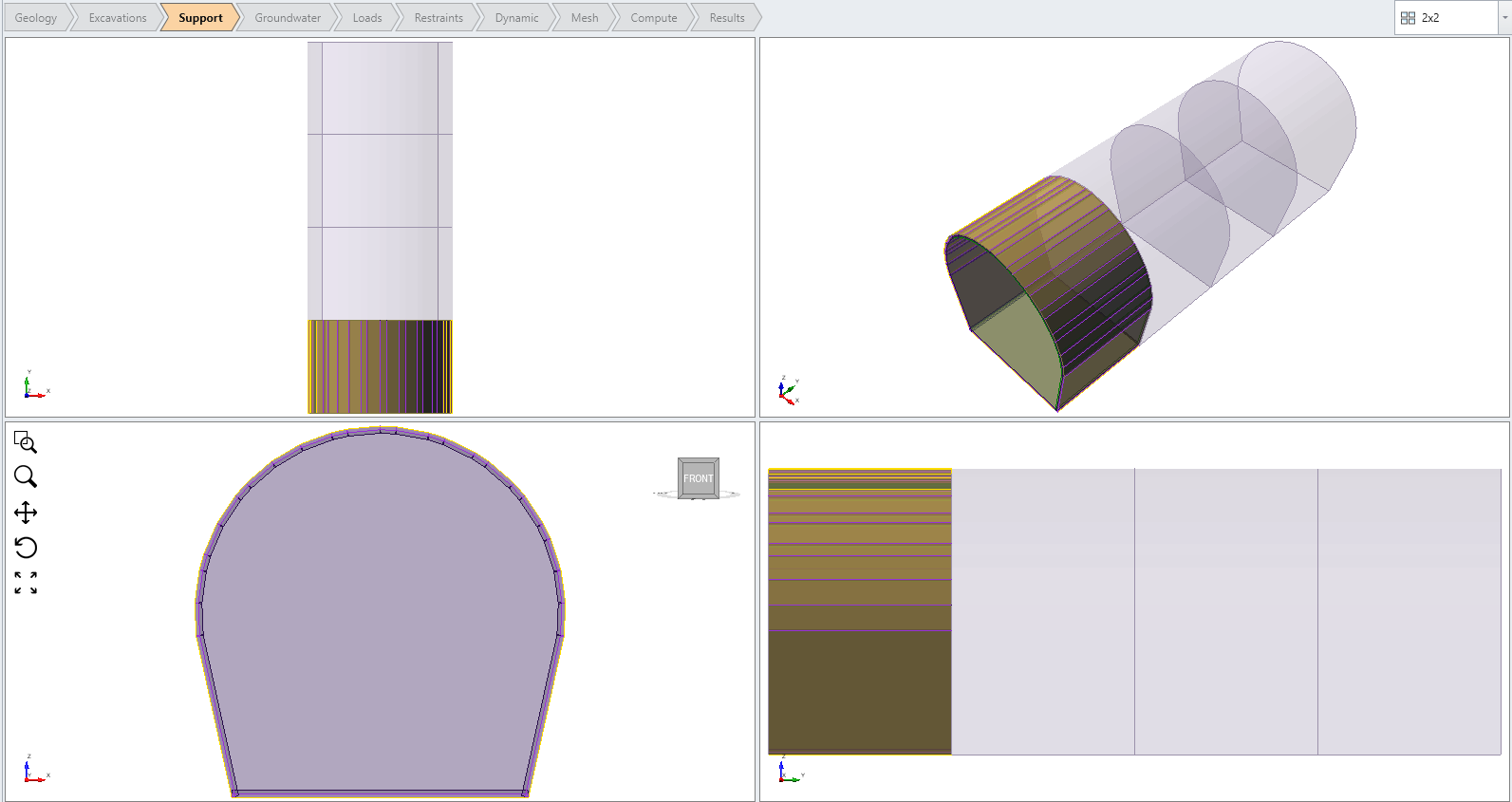
To display the full lining composition, you can use the Expanded View option in the Properties pane (which is highlighted in the image below). Users can view all layers within the lining set, as well as the layer order correspond to the surfaces. Steps are followed:
- Select the lining entity from the Visibility Tree. Hide other entities if necessary.
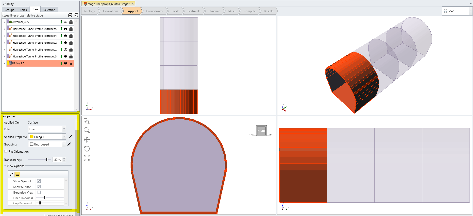
Lining Composition - Select Entity - Under the Properties pane (as highlighted in the image above), select the checkbox for Expanded View.
- Adjust the slide bar for Liner Thickness and Gap Between Liners to customize the view.
- Now all components within the lining set will be displayed, as shown in the image below.
