Define Liner Local Coordinates for Tunnels
This feature allows the user to easily define the liner local coordinate system using the tunnel direction and side faces. This allows the liner local coordinate system to follow the tunnel shape.
To use this feature, do the following:
- Select the tunnel side faces with Faces Selection
 (hold SHIFT during selection to select all connected faces).
 - Select Support > Liners > Define Liner Local Coordinates for Tunnels.
- In the Define Liner Local Coordinates for Tunnels dialog, use Select Edge or Trend and Plunge tabs to define the tunnel direction. See below for a description of each method.
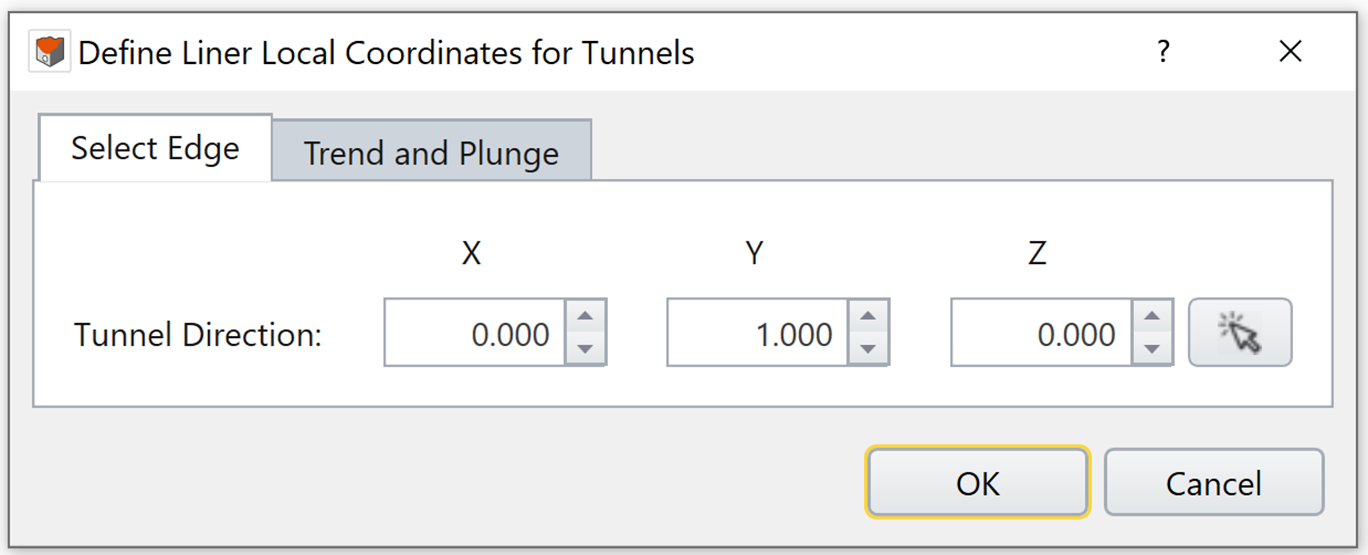
Select Edge
This option allows users to select an edge to define the tunnel direction. By default, the global Y axis, vector of (0, 1, 0), is assumed to be the tunnel direction. There are two ways to change the tunnel direction:
- Enter a new tunnel direction vector in the X, Y and Z input boxes, or
- Select the Mouse Click button
 and select an edge in the viewport. The X, Y and Z input boxes for the tunnel direction vector will be automatically updated from the direction of the selected edge.
Trend and Plunge
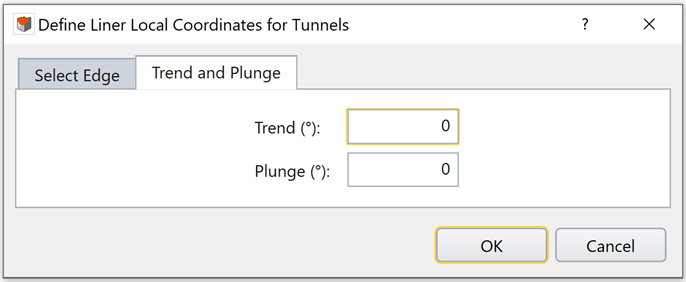
This option allows users to define the tunnel direction by defining trend and plunge angles. See the help page Sign Convention - Trend/Plunge for trend/plunge sign convention in RS3.
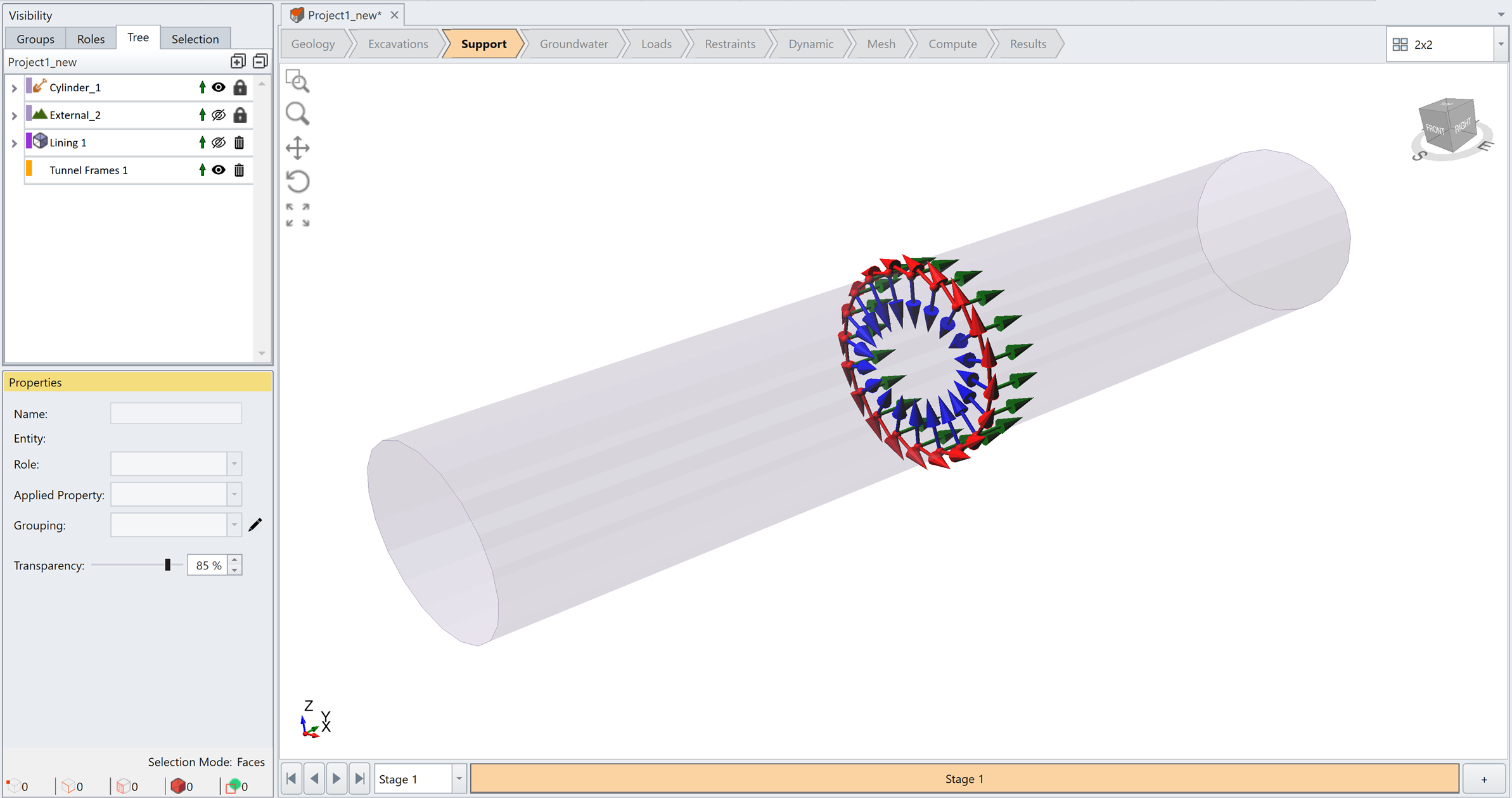
Click OK to create the liner local coordinate system. A new frame entity is created under the visibility tree. Notice that the local axes change according to the orientation of each side face on the tunnel. Liner results will be converted to the frame’s local coordinate system. (See Liner Local Coordinate Results).
Example
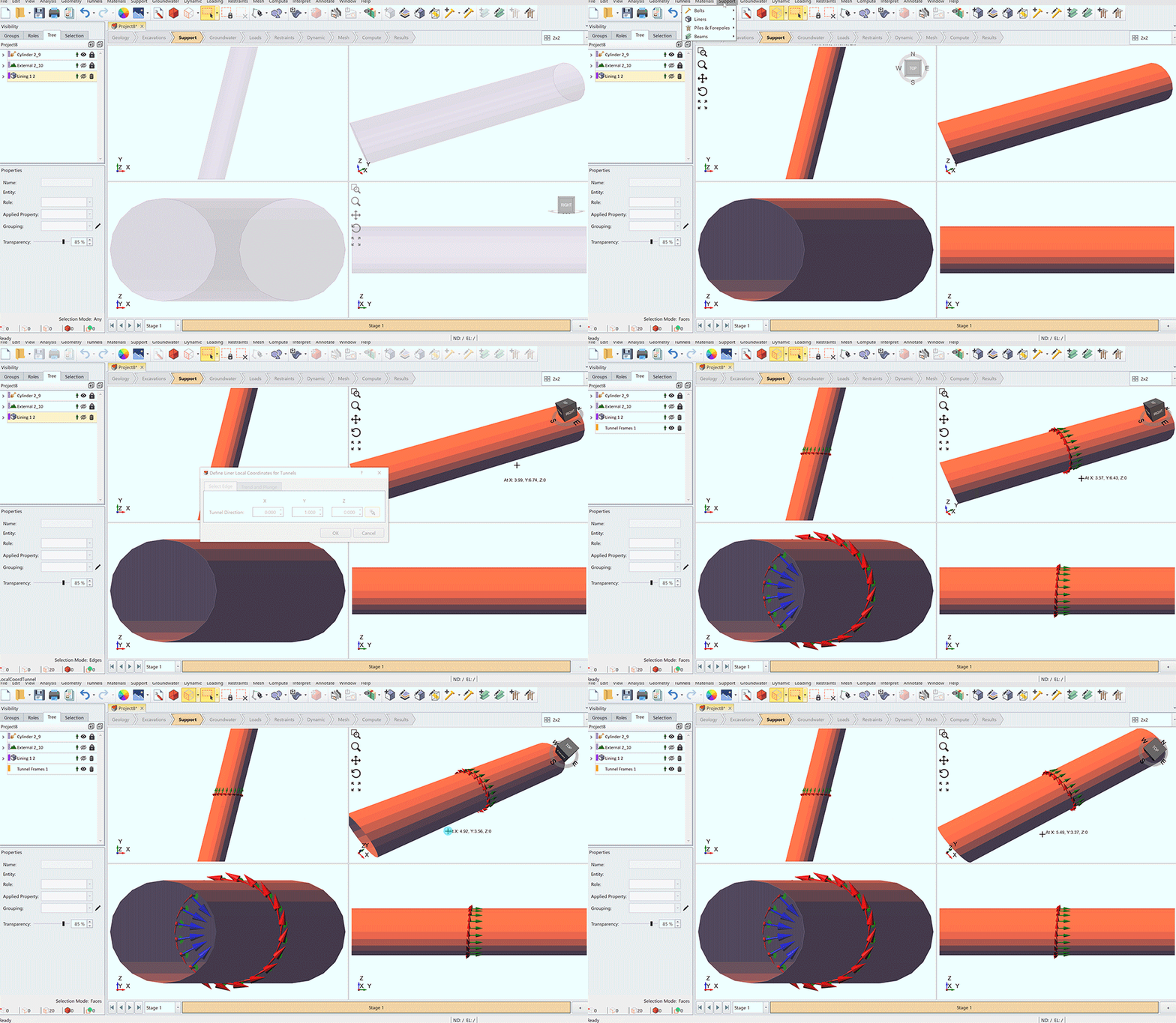
An example to illustrate the Define Liner Local Coordinate For Tunnels application process is given below. In the model, an excavated tunnel is supported with liners. The Define Liner Local Coordinate For Tunnels option was used to better analyze the liner results in a local coordinate system. Edge Selection method is used in this example.
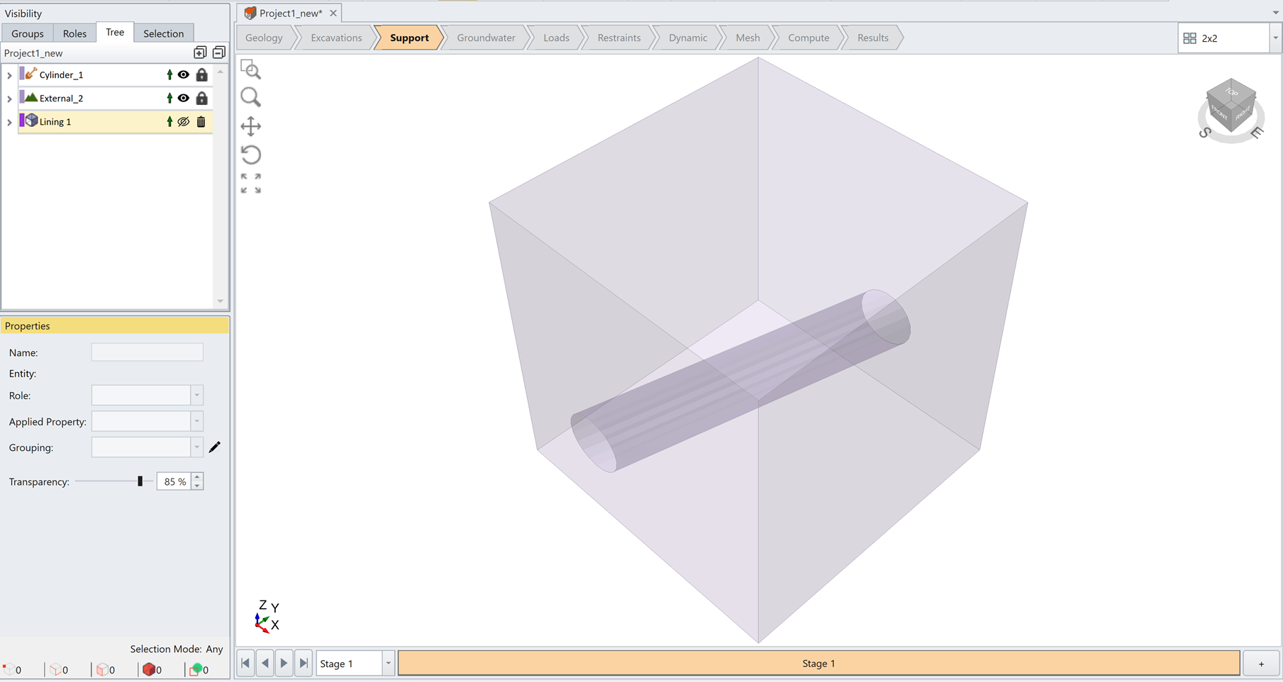
As seen in the images below, by selecting the edge, the tunnel direction is defined by vector [0.243, 0.970, 0]. A new liner local coordinate system (frame) is created, with local Y axis pointing in the tunnel direction. The local XZ plane is the cross-section of the tunnel. A GIF animation is also provided below.

To view and interpret liner results in local coordinate, please see RS3 Liner Contour Results - Liner Local Coordinate Results.