Support Element Interaction
Practical Consideration of Composite Liner Installation
Liner element (plate elements) in RS3 is a type of structural elements designed to model ground surface support, such as shotcrete (or reinforced shotcrete), sheet pile, diaphragm wall, geogrid, et cetera. RS3 integrates interface elements with liner elements to represent the adhesion or contact between different layers of surface supports or between surface support and soil or rock, accommodating for the sliding and opening mechanism between these entities. The Composite Liner feature enables accumulating the liner and interface elements in in various combinations.
When modeling the shotcrete applied on the underground tunnel walls, composite liner with interface-liner configuration (or liner-interface configuration) can be used to reproduce both the adhesion of shotcrete to the rock mass and the shotcrete layer. In this case, it is important to ensure that the interface is correctly placed (either above or below the liner) between the liner and the external volume representing the rock mass. If placed other way around, the interface would not form.
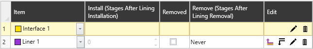
Figure below shows the example schematic of composite liner applied on the excavated tunnel wall such that the interface sits between liner and the solid external volume.

To ensure the composite liner is installed as planned, use the Expand View feature under the Properties pane for each lining composition. This allows you to clearly visualize the individual layers of the liner, as shown in the image below.
To support modeling Sheet pile or Diaphragm wall, where the steel sheets or reinforced concrete slab (respectively) is embedded within the soil, interface can be added on both sides of liner’s surface. This can be represented by adding interfaces above and below a liner layer to generate a composite liner with an interface-liner-interface configuration. Again, if the interface on one side of the liner and the other side is distinguished, it is important to make sure the interfaces are facing the appropriate sides from liner.
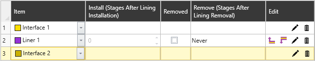
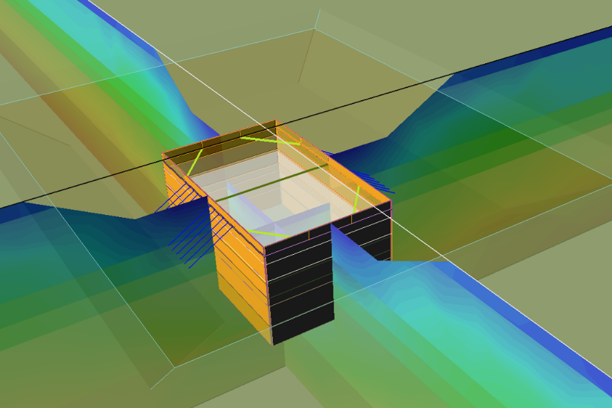
Figure below shows the example schematic of composite liner installed between two non-excavated (solid) volumes with interface 1 sitting between the liner layer and Solid volume 1 and the interface 2 between the liner layer and Solid volume 2.

Load Application and Composite Liner
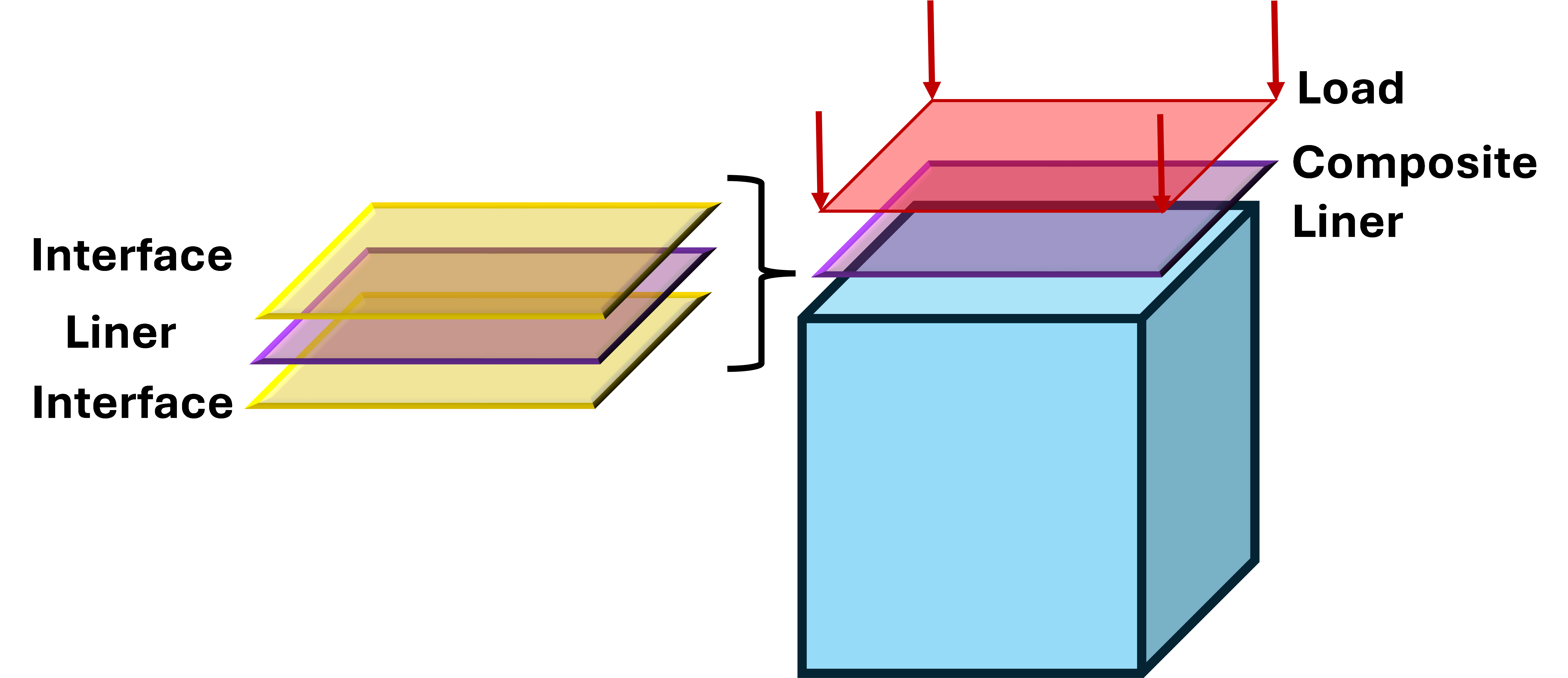
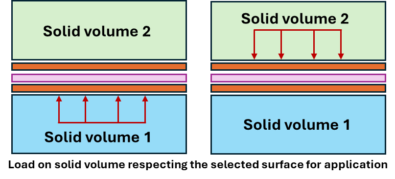
The application of load on a surface that has composite liner with layers of interfaces and liners can be ambiguous, as it is not clear the load is applied to the surface or the liner. This section explains the logic implemented in RS3 for surface load and composite liner interactions. The composite liner is treated as having an interface-liner-interface layer configuration, as illustrated below.
Composite liner and load application can be categorized into three different scenarios:
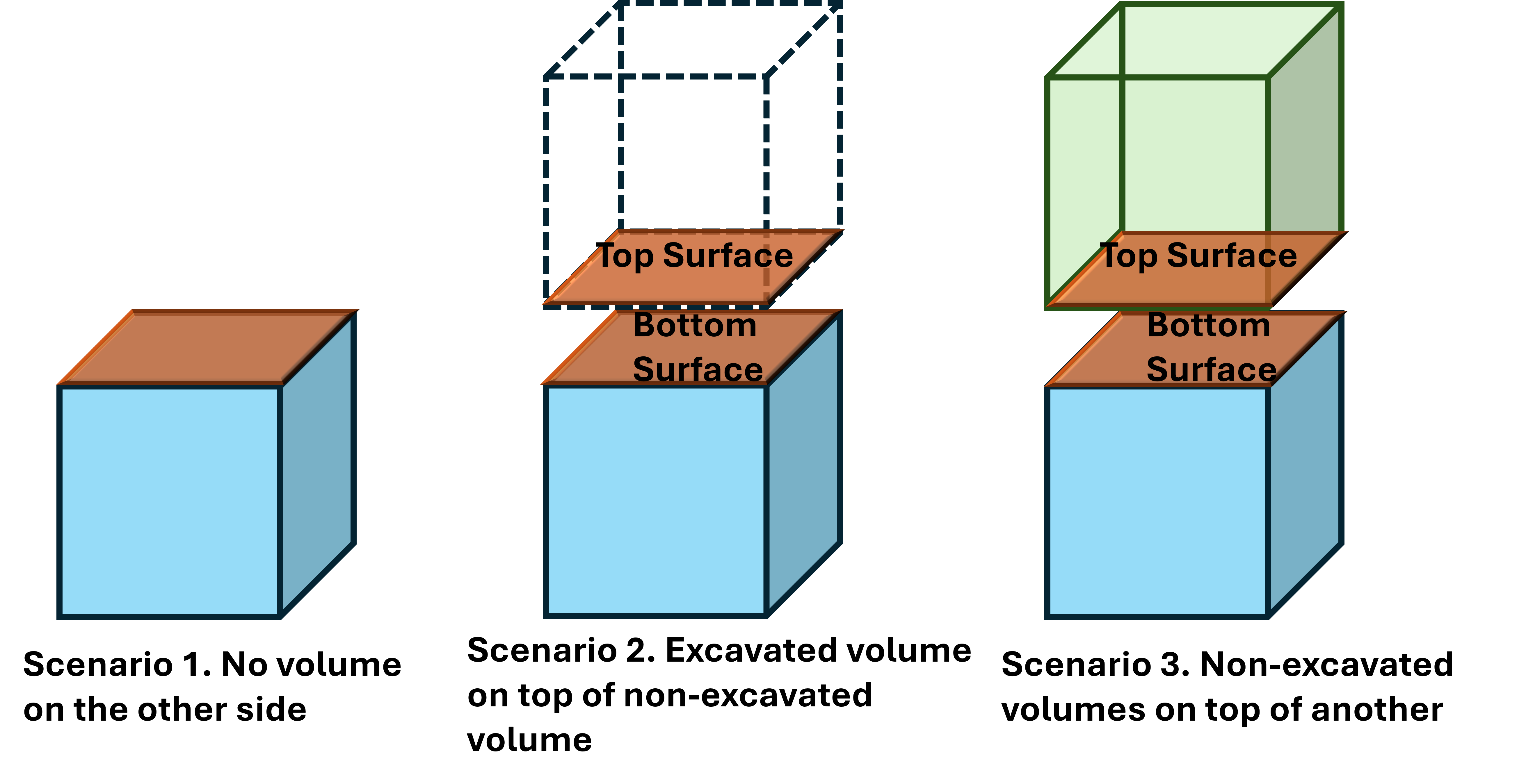
Scenario 1: When no volume exists on the opposite side of the surface
The upper interface layer of the composite liner is not generated due to the absence of a medium above the liner. The sequence of composite liner and load application is considered:
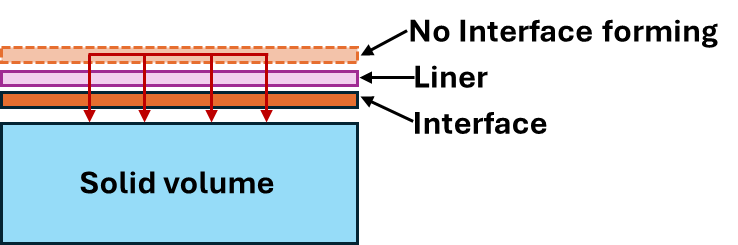
- If the load is applied at the same stage or after the composite liner is installed, the load is applied to the liner elements.
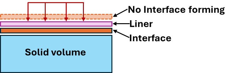
- If the load is applied before the liner is installed, the load remains applied to the solid elements even after the liner is added (below the interface).
Scenario 2: When excavated volume exist on the opposite side
In this scenario, the upper interface layer of the composite liner is not generated between the liner and the excavated volume. This scenario includes four cases of the load being applied to the liner or on solid surface (below the interface):
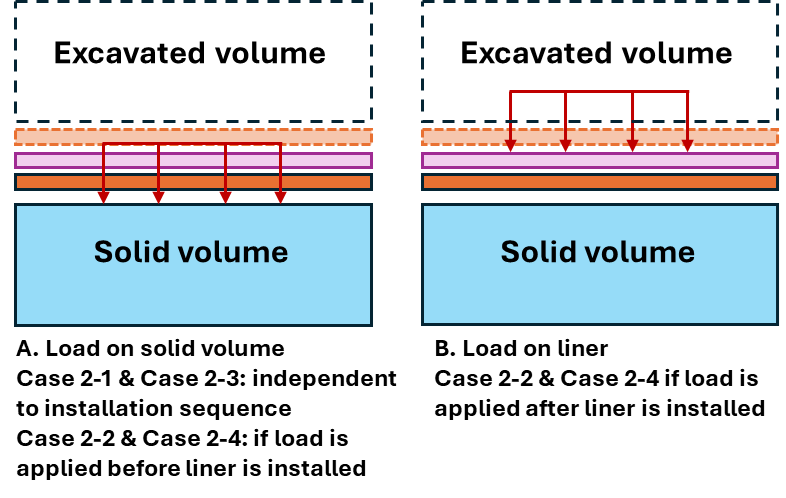
- Case 2-1 Both load and liner on the bottom surface (solid volume): The load is always applied to the solid elements, regardless of the application sequence.
- Case 2-2 Liner on bottom surface (solid volume) & load on top surface (excavated volume):
- If the load is applied at the same stage or after the composite liner is installed, the load is applied to the liner elements.
- If the load is applied before the liner is installed, the load remains applied to the solid elements even after the liner is added (below the interface).
- Case 2-3 Load on bottom surface (solid volume) & liner on top surface (excavated volume): The load is always applied to the solid elements, regardless of the application sequence.
- Case 2-4 Load & liner on top surface (excavated volume):
- If the load is applied at the same stage or after the composite liner is installed, the load is applied to the liner elements.
- If the load is applied before the liner is installed, the load remains applied to the solid elements even after the liner is added (below the interface).
Scenario 3: When volumes on both sides are not excavated
In this scenario, the load is always applied to the solid elements, ensuring it is applied to the selected solid surface. In the other word, if the load is applied to the bottom surface of the top solid, the load is assigned to the top of liner composition, and if the load is applied to the top of the bottom solid, the load is assigned to the bottom of the liner composition.
Liner interaction with other support elements
Liners are commonly used for ground surface support and interact directly with other support elements. This section outlines the connection logic implemented for structural elements in RS3.
Bolt-Liner Interaction
To simulate the interaction between the liner and the bolt, enabling the Face Plates option for bolts is necessary. The Face Plates option simulates the effect of face plates used on bolts.
- If the Face Plates checkbox is selected, the first vertex of each bolt is fixed to the external solid volume surface or existing liner, allowing the bolt to develop load starting at the face plate.
- If the Face Plates checkbox is not selected, the load at the bolt head is zero, meaning that the bolt is not connected to the liner or anchored at the surface of external solid volume
Note: The installation sequence assigned for bolt installation relative to the liner installation plays a role. For instance, if bolt with face plate is installed on a tunnel wall at the stage prior to the liner installation, load will not transfer from liner to the bolt or vice versa. This implies that the face plate remains directly on the surface of external solid volume element and does not update its location when the liner is applied.
Beam-Liner Interaction
Beam elements are typically used in pair with liner to represent the ground support systems for wall reinforcement and retainment functions. They are often used when modeling shores and deep excavation to represent sheet pile walls and structs and braces; and when modeling tunnels and shaft, beams and liners are used together to represent steel sets (or steel ribs) or lattice girder and shotcrete. In most cases, they are installed sequentially and RS3 attempts to connect those that are installed at the same stage or in subsequent stages. However, in current version of RS3 (4.037) and until further notice, controls are not provided to the beam elements over which liner layer the beam elements to connect with when they intersect a composite liner. If there is only one liner in the lining composition (typical case) the beam and the liner will be connected.
Pile-Liner Interaction
The connection between the pile head and the liner can be controlled from the pile properties dialog, in Connection Type section. For more information on the pile-liner connection, see Lining Connection Type section of Define Pile Properties documentation page here.