Import RS2 Project to RS3
This tutorial introduces the RS2 Import feature in RS3. You will be importing an RS2 project to RS3. All the RS2 supporting features are listed on the Import RS2 Project help page. The finished product can be found in the Materials and Staging - final.rs3v3 file.
1.0 Import RS2 Project
- Select File > Import > Import RS2 Project.
- In the RS3 tutorials folder, go to the Import RS2 Project to RS3 tutorial folder and select the Materials and staging.fez file. Note that the directory to the tutorials folder can be determined if you select File > Recent> Tutorials Folder
- The RS2 Import wizard will open as shown below.
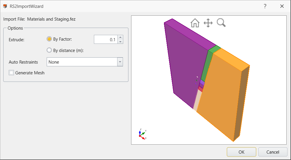
1.1 EXTRUDE
The Extrude option allows you to extrude the model in a factor. For instance, this RS2 project has dimensions of 332 meters in width by 348 meters in height. The RS2 model is projected in the XZ plane. When you choose Extrude with a factor of 0.1, RS3 extrudes the model along the y-axis in approximately 34.5 meters.
- For this tutorial, we will use Extrude By Factor of 0.1 (default option). We will keep the Auto Restraints option set to None and the Generate Mesh option unselected to prevent RS3 from automatically generating restraints and mesh.

- Click OK.
- The RS2 Import summary will appear.
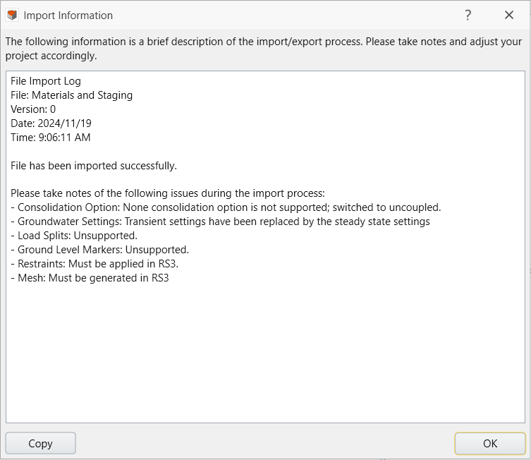
- Click OK.
3.0 RS3 Model
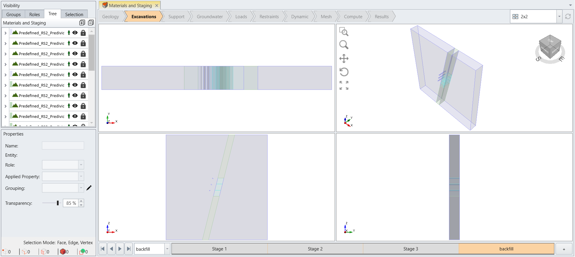
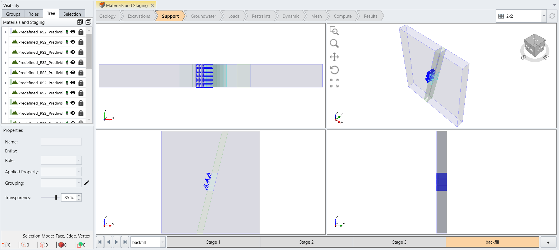
The imported model consists of orebody and the host rock. Longhole stopes are excavated over stages, and the access drifts are present to apply the cable support from the drifts to the hanging wall. This section explores the RS3 model settings automatically applied from the import function.
3.1 EXCAVATIONS
- Select the Excavations workflow tab

- Select the last stage (backfill). The model shows the three inclined stopes backfilled.
3.2 SUPPORT
- Select the Support workflow tab
 and you will see the applied bolts in the RS3 model.
3.3 RESTRAINTS
- Select the Restraints workflow tab

- Select Edit > Selection Mode > Faces Selection

- Under the Visibility pane, switch from the Tree tab.
- Select all front and back surfaces.
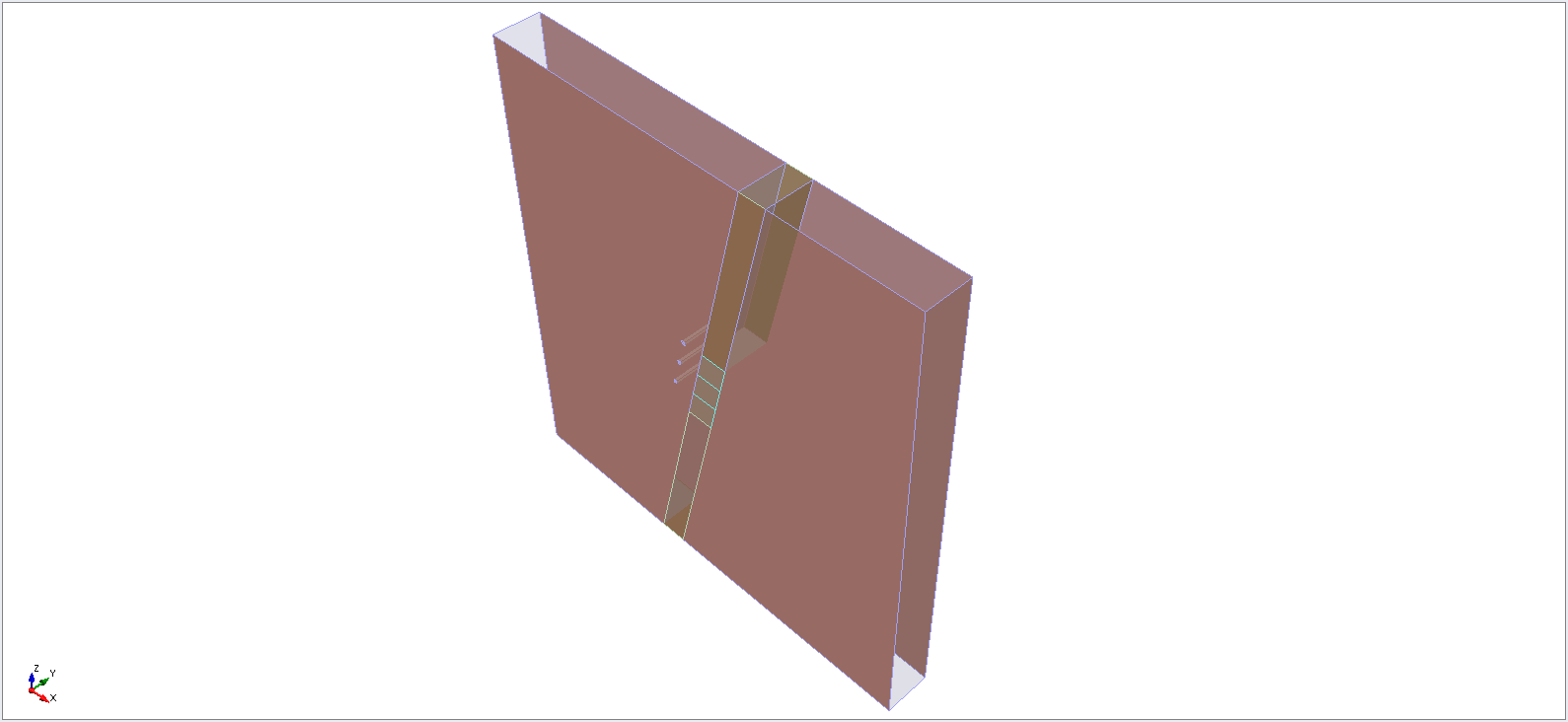
- Select Restraints > Add Restraints/Displacements > Restrain Y.
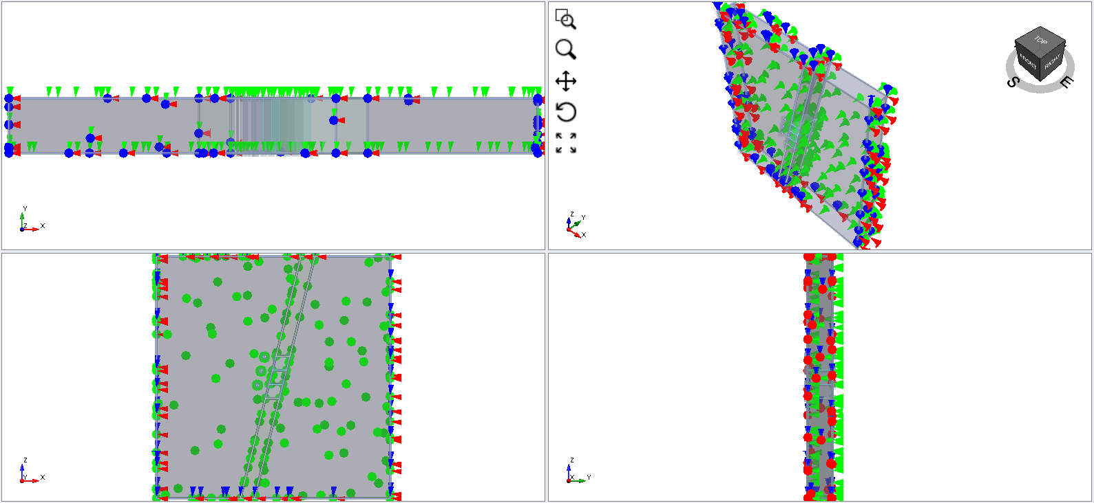
- Select the rest of the external surfaces (Right, Left, Top, and Bottom).
- Select Restraints > Add Restraints/Displacements > Restrain XYZ.
3.4 MESH
- Select the Mesh workflow tab

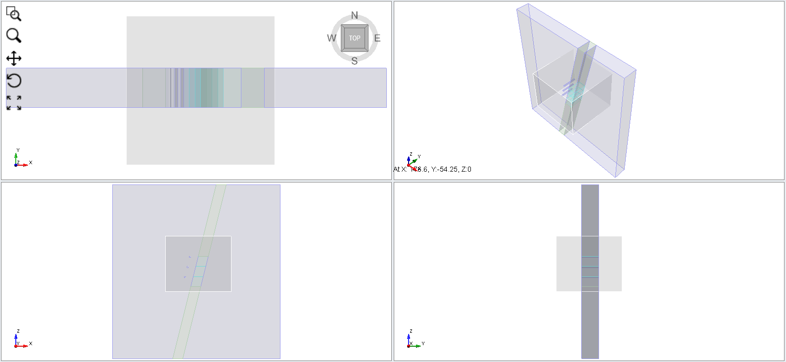
- Select Mesh > Mesh Refinement Region. Enter the following coordinates for two box corners:
- First corner: (-50, -50, 10).
- Second corner: (80, 80, 120).

- Select OK.
- You will be directed to set the distribution of the refined region. Keep it as Uniform, and change the Element Size to 4(m) and select OK.

- This generates a refinement box that represents the defined refinement region.
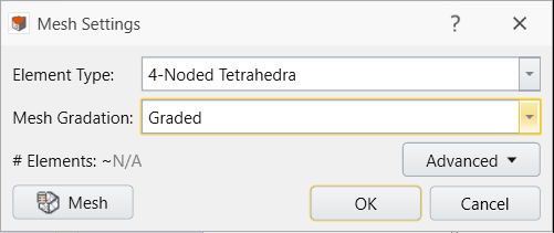
- Now select Mesh > Mesh Settings to apply these settings to the model.
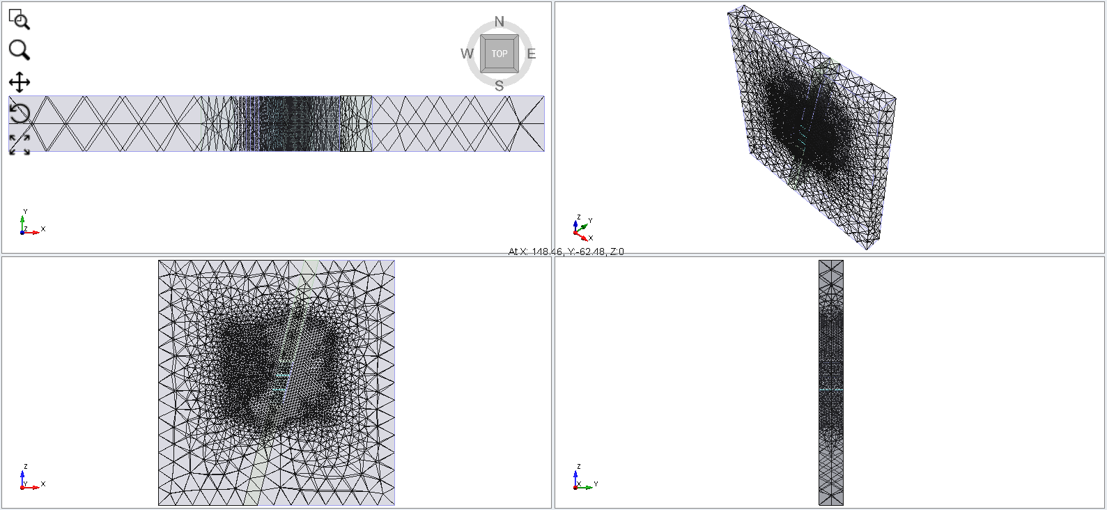
- The Mesh is generated as shown below:
4.0 Compute
- Select the Compute workflow tab

- From this tab, we can compute the results of our model. Before commencing the stress analysis computation, it is recommended to save the final model as a separate file so that you can access the original file anytime (File > Save As).
- Select Compute

5.0 Results
- Select the Results workflow tab

- Select Interpret > Show Excavation Contour.
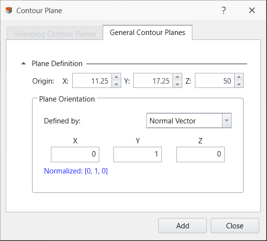
- Select Interpret Show Data on Plane > XZ and click Add with the default settings.
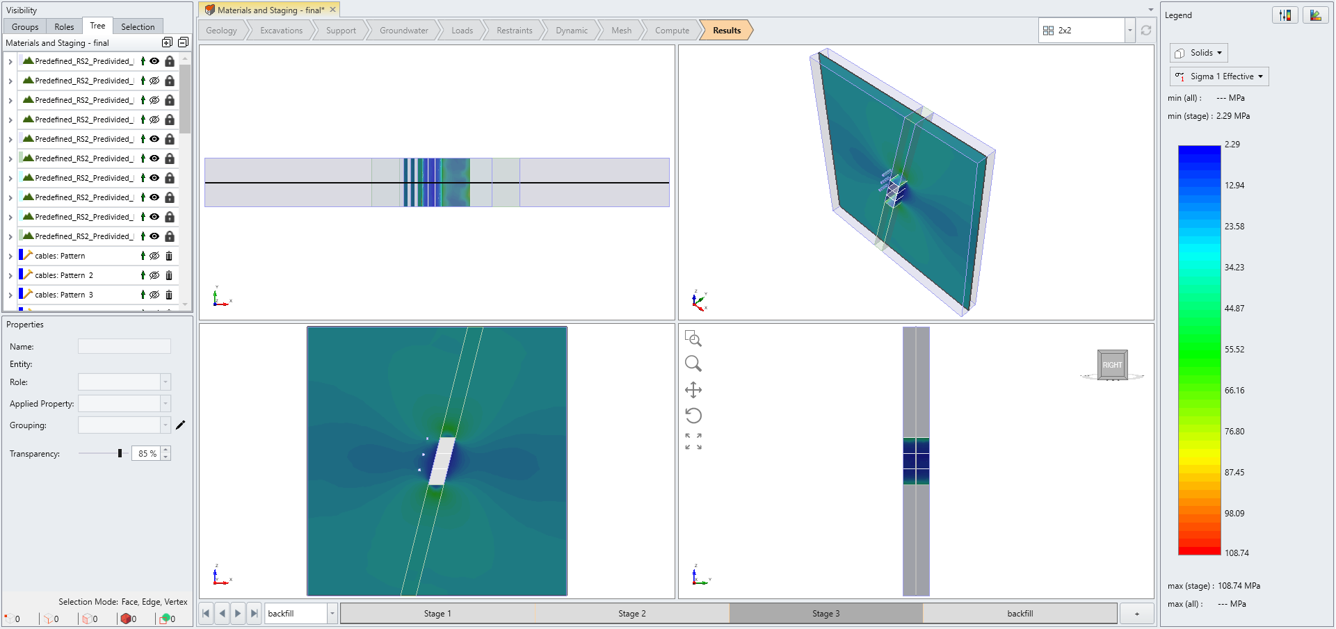
- For Solids > Sigma 1 Effective Stress, you will see the excavation contour with bolts at Stage 3 as shown below:
5.1 TOTAL DISPLACEMENT
- Select Solids > Total Displacement.
- Load the data for all stages by opening all four stages.
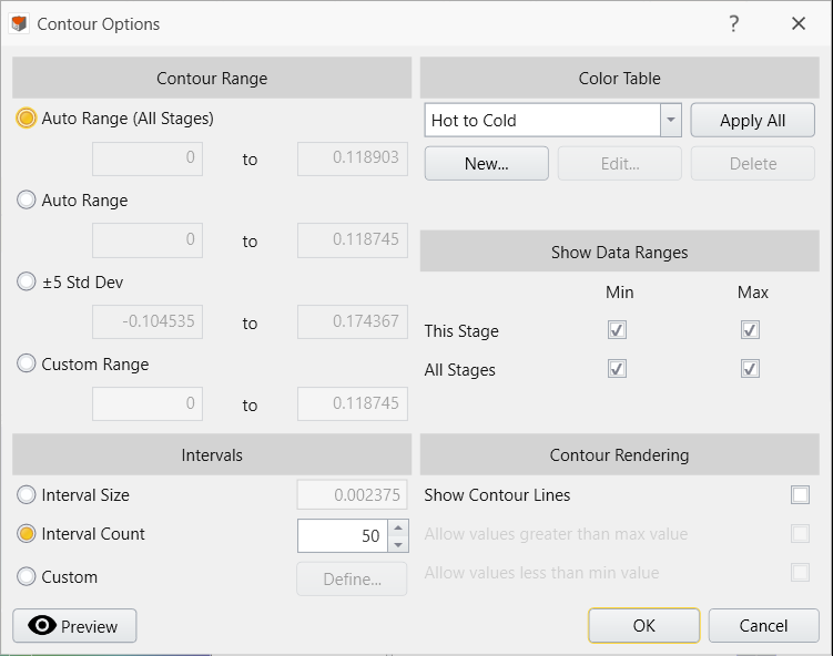
- Select Interpret > Contour Options > Contour Legend.
- Select Auto Range (All Stages).
Stage 1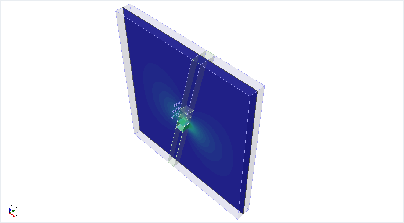 | 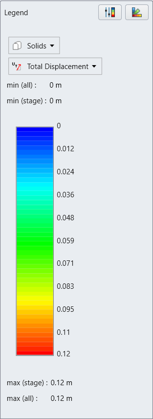 |
Stage 2  | |
Stage 3 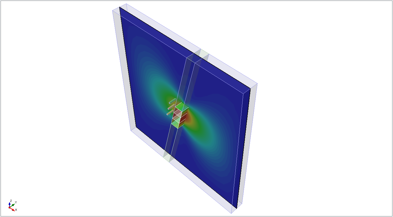 |
5.2 STRENGTH FACTOR AND YIELDED ELEMENTS
- Select Solids > Strength Factor to observe the strength factor of the excavated regions at different stages.
- Select Interpret > Contour Options > Contour Legend.
- Select Custom Range and set the range as 0 to 11.
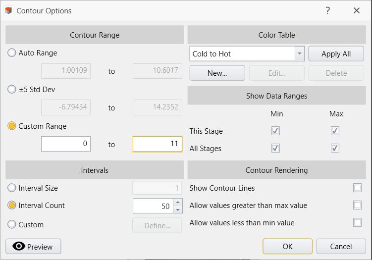
- Change the data contour to Yielded Elements.
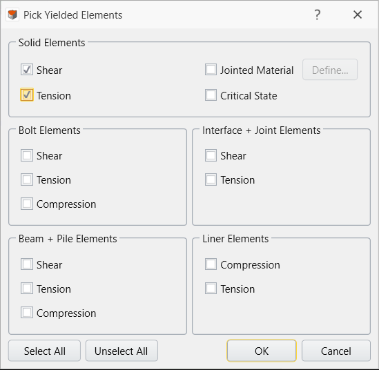
- Then select Interpret > Yielded Elements. Check off Shear and Tension yielded elements.
Stage 1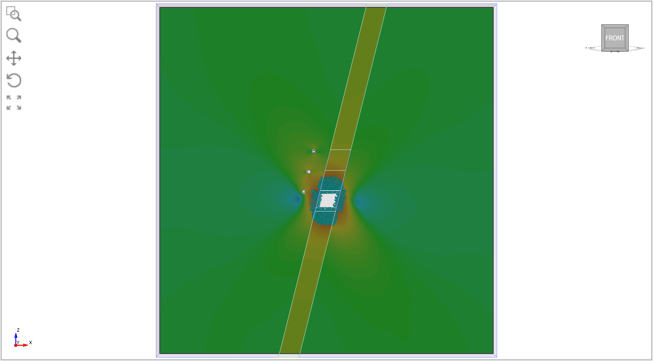 | 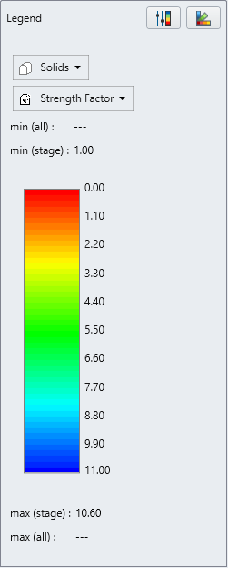 |
Stage 2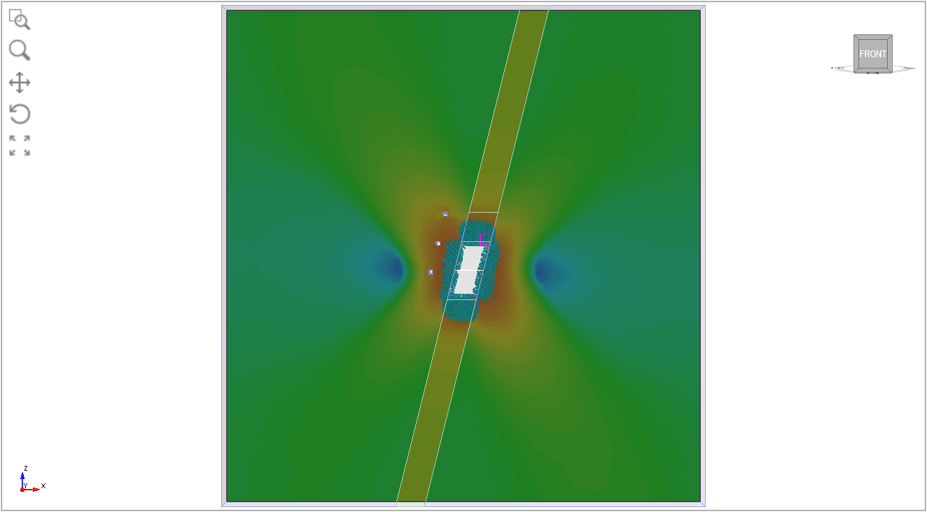 | |
Stage 3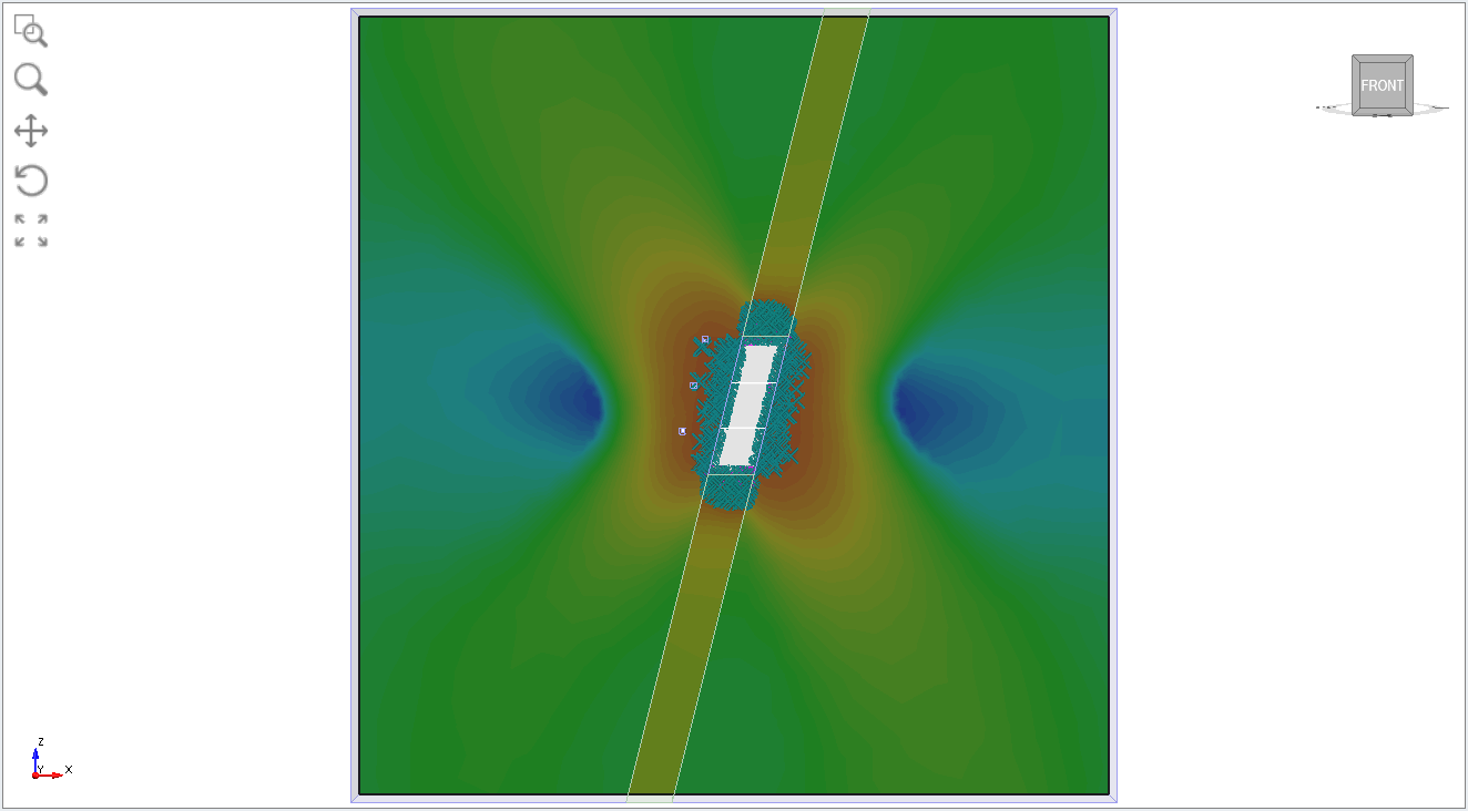 |
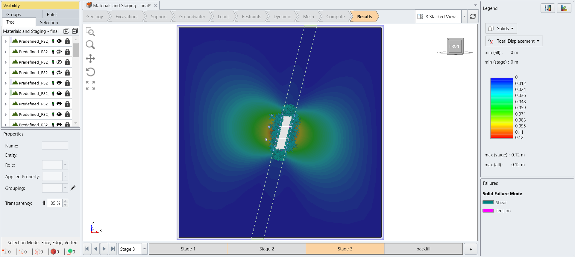
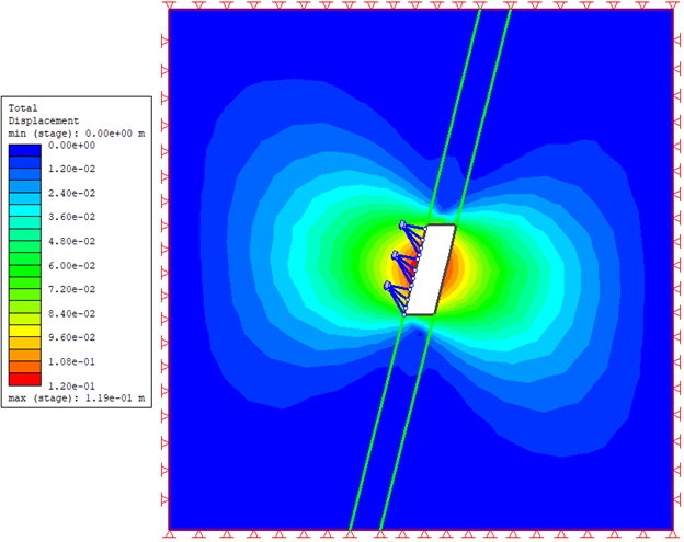
5.3 TOTAL DISPLACEMENT COMPARISON WITH RS2
This section provides a deformation comparison between RS2 and RS3 at Stage 3. The RS3 model was created by extruding the RS2 section by 1m, rather than by a factor of 1, to produce a thinner model. This model can be found in the same RS2 import tutorial folder under the name Material and Staging- ThinModel.rs3. Note that the computation time for this model may be longer than that of the tutorial model. By using a geometry that more closely resembles a 2D representation, the RS3 model produces results that align more closely with those of RS2.
This concludes the tutorial.