18 – Helical Pile Capacity
1.0 Introduction
This tutorial demonstrates how to analyze a single helical pile in multiple soil layers under various conditions in RSPile.
Topics Covered in this Tutorial:
- Multi-layer model
- Soil types for helical piles
- Pile properties
- Export data to Excel
Finished Product:
The finished product of this tutorial can be found in the Tutorial 18 Helical Pile Capacity.rspile2 data file. All tutorial files installed with RSPile can be accessed by selecting File > Recent Folders > Tutorials Folder from the RSPile main menu.
2.0 Model
When the RSPile program is started, a new blank document is already opened, allowing you to begin creating a model immediately.
2.1 Project Settings
- Select Home > Project Settings (CTRL + J)

- In the General tab enter:
- Units = SI (Metric)
- Program Mode Selection = Capacity Calculations
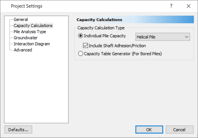
- In the Capacity Calculations tab enter:
- Capacity Calculation Type = Helical Pile
- Tick the checkbox for Include Shaft Adhesion/Friction
-
In the Groundwater tab, tick the Groundwater Analysis checkbox.
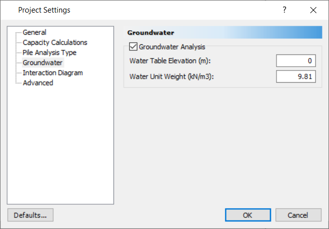
- Click OK to close the dialog.
2.2 Soil Properties
- Select Soils > Soil > Define Soil Properties (CTRL + 8)

- Define the material properties as shown below:
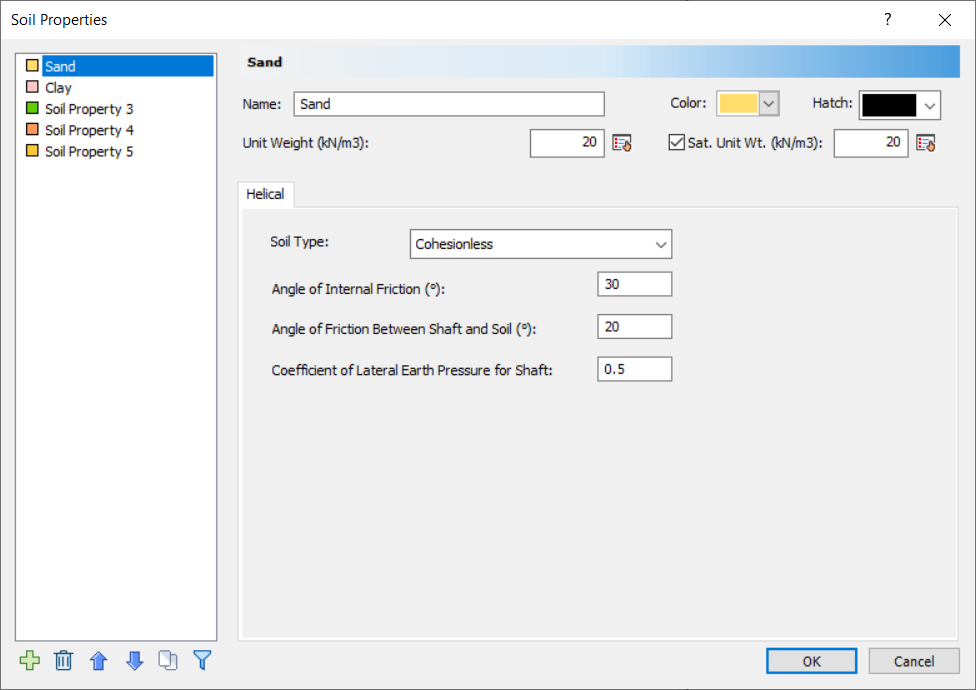
Soil Property 1:
- Name = Sand
- Unit Weight = 20 kN/m3
- Sat. Unit Weight = 20 kN/m3
- Soil Type = Cohesionless
- Angle of Internal Friction = 30 degrees
- Angle of Friction Between Shaft and Soil = 20 degrees
- Coefficient of Lateral Earth Pressure for Shaft = 0.5
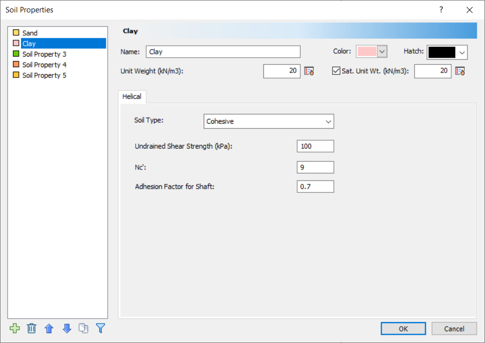
Soil Property 2:
- Name = Clay
- Unit weight = 20 kN/m3
- Sat. Unit Weight = 20 kN/m3
- Soil Type = Cohesive
- Undrained Shear Strength = 100 kPa
- Nc’ = 9
- Adhesion Factor for Shaft = 0.7
- Click OK to close the dialog.
2.3 Soil Layers
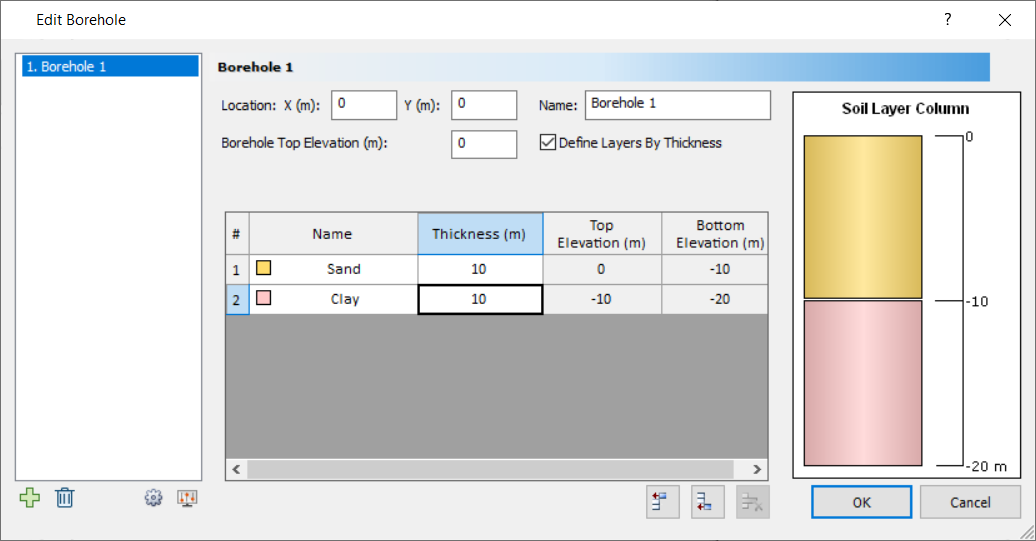
RSPile supports multiple boreholes and non-horizontal soil strata. When multiple boreholes are defined, the program will automatically interpolate between the boreholes. In this tutorial, we will model horizontal soil strata with a single borehole. To begin:
- Select Soils > Boreholes > Edit All
 to open the Edit Borehole dialog.
 - We will keep the borehole location and top elevation 0 for this tutorial.
- Click on Insert Layer Below
 to add another layer below the first.
 - Specify the following layer thicknesses:
- Click OK to save the soil layers and exit the dialog.
| # | Name | Thickness (m) | Top Elevation (m) | Bottom Elevation (m) |
| 1 | Sand | 10 | 0 | -10 |
| 2 | Clay | 10 | -10 | -20 |
2.4 Pile Section Properties
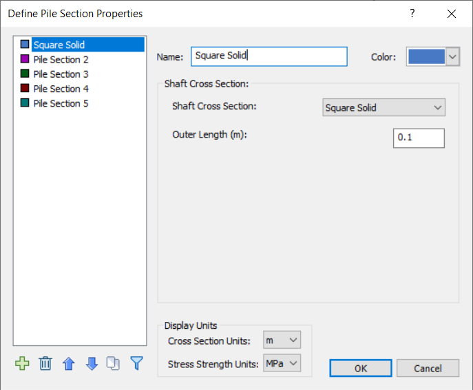
To define the shaft’s cross section properties:
- Select Piles > Pile Properties > Pile Sections

- For this tutorial, we will examine a built-up helical pile consisting of two sections:
- For Pile Section 1, set the following:
- Name = Square Solid
- Shaft Cross Section = Square Solid
- Outer Length = 0.1m
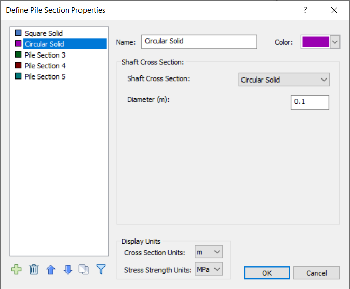
- For Pile Section 2, set the following:
- Name = Circular Solid
- Shaft Cross Section = Circular Solid
- Diameter = 0.1m
- For Pile Section 1, set the following:
- Click OK to save the sections and proceed with defining the shaft.
2.5 Pile Types
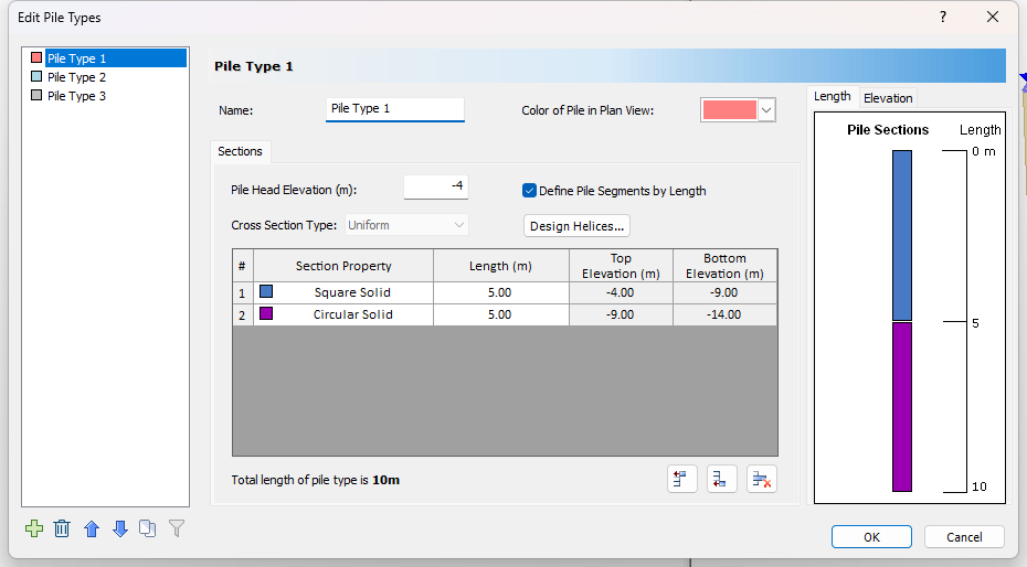
To define the shaft:
- Select Piles > Pile Properties > Pile Types

- Enter Pile Head Elevation (m) = -4
- Click Insert Segment Below to add another segment below Segment #1.
- Change the Section Property of the second segment to Circular Solid.
- Set the Length of each segment to 5m.
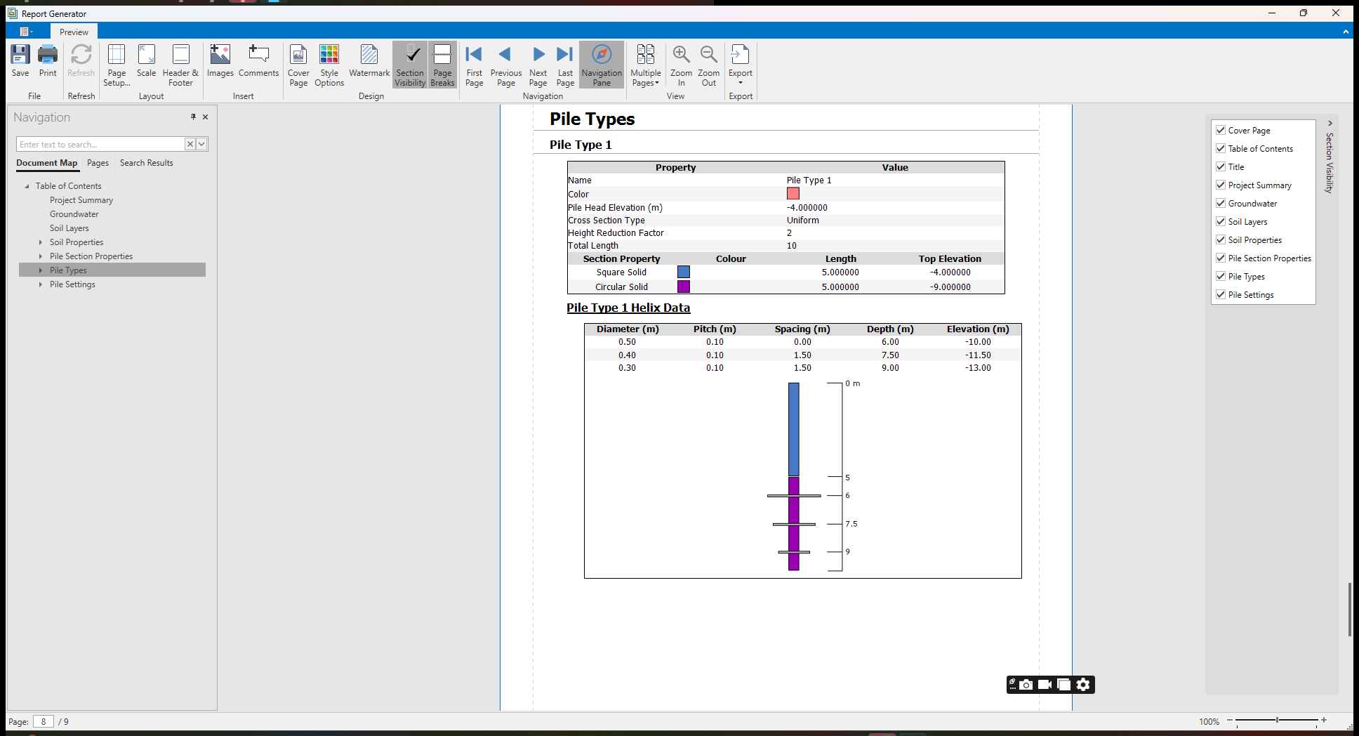
The pile type configuration should appear as follows:
2.5.1 Define Helices
After creating the shaft in the Edit Pile Types dialog, define helices along the shaft:
- Click Design Helices to open the Edit Helices dialog.
- Enter Depth of First Helix from Pile Head = 6m
- Keep the default radio button selection as Spacing.
- Keep the default Height Reduction Factor as 2.
- Click Add Helix Below to add a helix.
For this tutorial, we will determine the capacity of a helical pile with three helices.
- Set the helix properties to the following:
- Click OK to save the input and close the Edit Helices dialog. Click OK again to close the Edit Pile Types dialog.
| # | Diameter | Pitch (m) | Spacing (m) | Depth (m) | Elevation (m) |
| 1 | 0.5 | 0.1 | - | 6 | -10 |
| 2 | 0.4 | 0.1 | 1.5 | 7.5 | -11.5 |
| 3 | 0.3 | 0.1 | 1.5 | 9 | -13 |
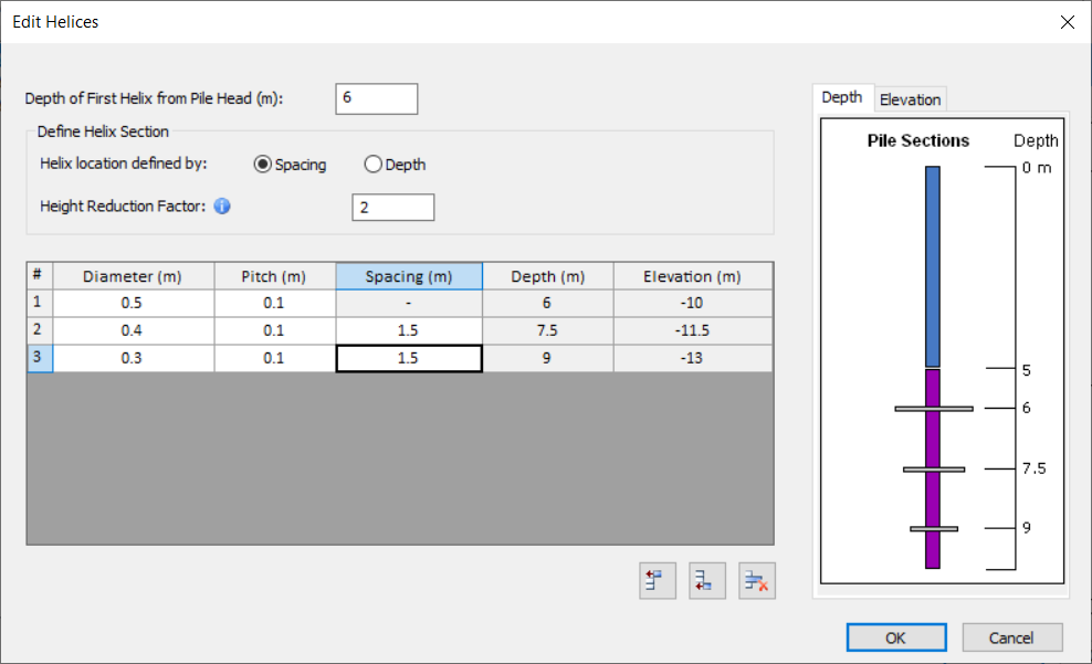
Users can specify helix locations either by depth or by spacing:
- By Spacing: When defining helix locations using spacing, the entered spacing value is measured relative to the helix positioned above it. The position of the first helix is determined by the Depth of First Helix input from the pile head.
- By Depth: Alternatively, if helix locations are defined by depth from the pile head, users can manually input the position of each helix along the length of the pile.
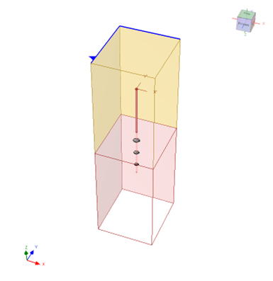
2.6 Add Pile
To add the helical pile:
- Select Piles > Add Piles > Single

- Leave the default (X, Y) location as (0, 0) and click OK to add the pile to the screen.
To view the helical pile, you may disable Boreholes from the View Controls on the left side of the screen.
3.0 Results
To compute the capacity of the pile:
- Select Results > Compute (Ctrl + T)

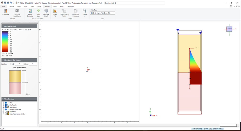
3.1 Result Visualization
After computing, the Unit Skin Friction on the shaft is shown along the length of the pile by default. In the Results tab, use the Data Type dropdown to control what results are shown.
The results can be viewed along the depth of the pile in the 3D view. Below are the results for Shaft Friction/Cyl. Shear (C):
3.2 Charts
- Right-click on the pile and select Graph Pile

You will see results for compression and uplift in separate tabs, and by default the first tab is for Total Compression Results.
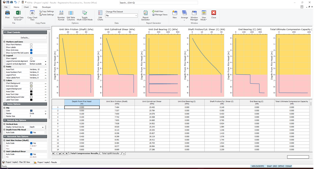
For both compression and uplift, you will see the following results:
- Unit Skin Friction (Shaft) vs. Depth
- Unit Cylindrical Shear vs. Depth
- Unit End Bearing vs. Depth
- Shaft Friction/Cyl. Shear vs. Depth
- End Bearing vs. Depth
- Total Ultimate Capacity vs. Depth
The sidebar contains the Chart Controls, which allow you to select what information is displayed and customize the appearance. The charts that are displayed, as well as the displayed tables, can be changed by right-clicking in the chart area and selecting what data you would like to edit in the dropdown menu.
3.3 Export to Excel
From the Chart tab, you can export the data to Excel.
- Click the Export Data to Excel
 icon in the toolbar.
Each data type will be exported to its own sheet in the Excel file.
4.0 Report Generator
- Return to the model view and select Results > Report Generator > Report Generator

The Report Generator will contain a summary of the model input data:
- Project Summary
- Soil Layers
- Soil Properties
- Pile Section Properties
- Pile Types
- Pile Settings
The toolbar contains the Report Generator Controls, which allow you to select what information is displayed and customize the appearance.
The data can be exported in a variety of ways. It may be manually copied, viewed in a browser, printed, or the information may be saved as a .pdf file.
The helix data is viewable under the Pile Types section of the Report Generator.
Close the Report Generator window to return to the model view.
This concludes the Helical Pile Capacity Tutorial. You may now exit the RSPile program.