21 - Pile Head Stiffness Matrix and Spring Constants
1.0 Introduction
This tutorial covers how to obtain the Pile Head Stiffness Matrix and Simplified Spring Constants of a reinforced concrete pile under various loading conditions in RSPile.
Topics Covered:
- Pile Head Stiffness Matrix
- Simplified Spring Constants
Finished Product
The finished product of this tutorial can be found in the Tutorial 21 - Pile Head Stiffness and Spring Constants.rspile2 data file. All tutorial files installed with RSPile can be accessed by selecting File > Recent Folders > Tutorials Folder from the RSPile main menu.
1.1 Problem description
Say we have a reinforced concrete rectangular pile with:
- B = 0.8 m
- W = 1.2 m
The section is reinforced with 32 mm bars. There are 7 peripherally distributed bars on each width side (x’) and another 3 intermediate 32mm bars at each of the breath sides, giving a total of 20 bars.
- f’c=50MPa
- Es=200000MPa
- Fy=420MPa
The pile will be 20m long in a competent stiff clay, with an undrained shear strength Su=250kPa, and the adhesion factor for skin friction = 0.5.
Required:
We will use RSPile to obtain the following:
- The pile head stiffness matrix for the following loading conditions
Fx = 1000 kNMy = 750 kN.mFy = 500 kNMx = -750 kN.mFz = -10 000 kNusing 10 equal steps of load levels. - The direct spring constants using the simplified spring constants option.
2.0 Model Pile Head Stiffness Matrix
2.1 Project Settings
Begin by defining your Project Settings:
- Select Home > Analysis > Project Settings

- Go to the Pile Analysis Type tab.
- Select Individual Pile Analysis = Axially / Laterally Loading
- Check the box for Include P-Delta Effect
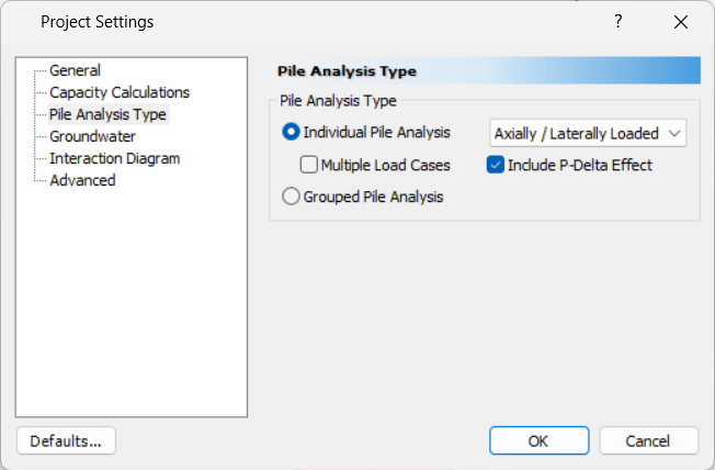
- Click OK to close the dialog.
2.2 Soils
- Select Soils > Soil > Define Soil Properties

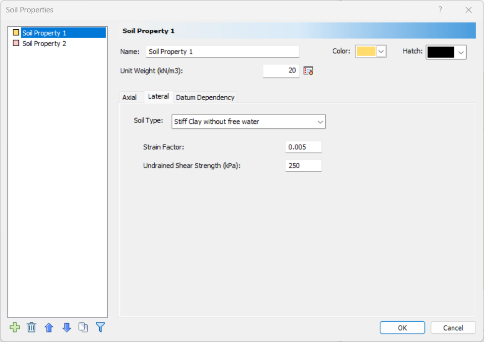
- For Soil Property 1, select the Lateral tab.
- Enter:
- Soil Type = Dry Stiff Clay
- Undrained shear strength = 250kPa
- Select the Axial tab.
- Enter:
- Soil Type = Drilled Clay
- Ultimate Shear Resistance = 125 kPa (assuming adhesion=0.5*cohesion)
- Enter Ultimate End Bearing Resistance = 2250 kPa (maximum end bearing is 9*250 = 2250kPa)
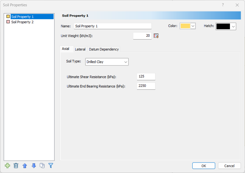
- Click OK to close the dialog.
2.3 Piles
2.3.1 Define Pile Section Properties
- Select Piles > Pile Properties > Pile Sections

- For Pile Section 1, select Section Type = Reinforced concrete.
- Enter Compressive Strength f’c = 40MPa
- For the Cross Section enter:
- Cross Section = Rectangular
- Section Width = 1.2 m
- Section Depth = 0.8 m
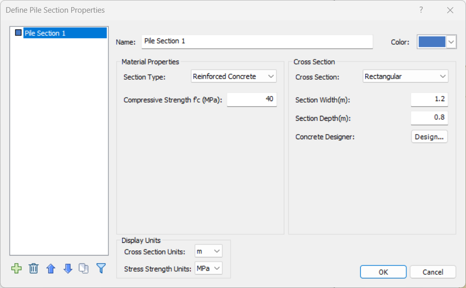
- Open the Concrete Designer by clicking Design…
- In the Reinforcement tab, click Add to add a Reinforcement pattern.
- Enter:
- Rebar Size = Europe > CEB 32 mm
- Pattern Type = Rectangle
- Check the Peripheral bars box for peripheral distribution.
- Number of Bars in X’ = 7
- Number of Bars Y’ = 5
- Min Cover Depth = 87 mm
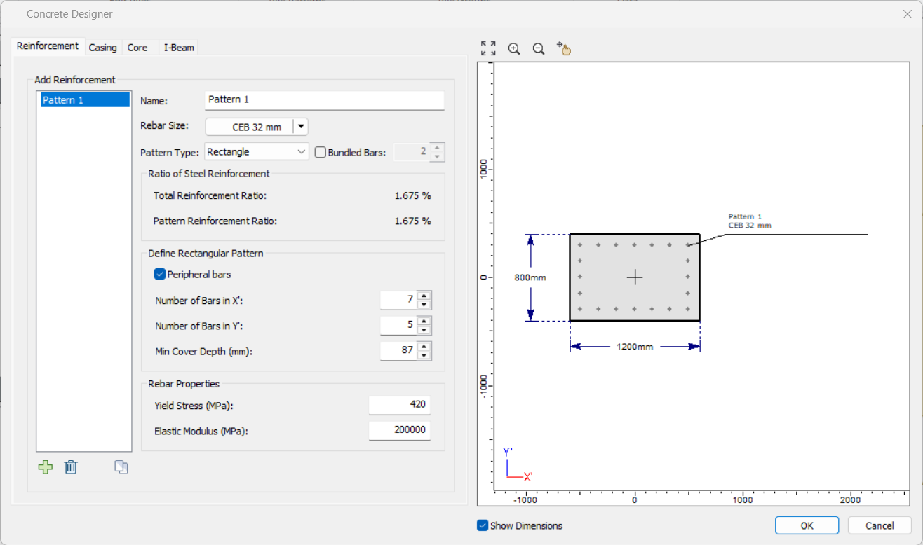
- Click OK to close the Concrete Designer. Your section is ready.
- Click OK again to close the Pile Section dialog.
2.3.2 Pile Types
- Select Piles > Pile Properties > Pile Types

- For Pile Type 1:
- Section Property = Pile Section 1
- Length = 20m

- Click OK to close the dialog.
2.3.3 Define Loading Property
- Select Piles > Add Piles > Single

- In the Loading tab, click Add to add a Loading Property.
- Change the Loading Direction to General.
- Click the Add
button at the bottom of the dialog to add the following loads:
- Force X (kN) = 500
- Moment Y (kNm) = 375
- Force Y (kN) = 250
- Moment X (kNm) = -375
- Force Z (kN) = - 5000
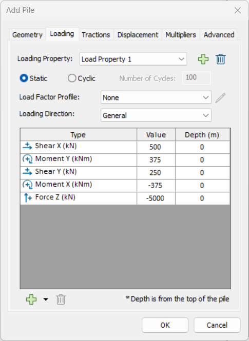
The loads are as shown above (as required to be half of the maximums given in the problem data).
2.3.4 Stiffness Matrix Calculator
- In Advanced tab, check the box for Stiffness Matrix Calculator.
- A dialog will open. Enter Number of Steps = 10 and Load Division = Evenly Spaced. Fill in the loads as below:
- X Direction
- Force X (kN) = 1000
- Moment Y (kNm) = 750
- Y Direction
- Force Y (kN) = 500
- Moment X (kNm) = -750
- Z Direction
- Force Z (kN) = -10 000
- X Direction
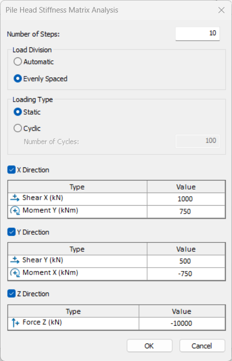
Here you filled the maximum loads given in the problem data.
- Click OK to close the dialog and return to the Advanced tab.
2.3.5 Simplified Spring Constants
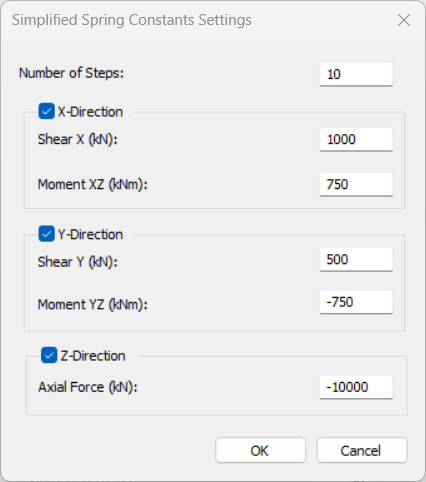
- In the Advanced tab, check the box for Simplified Spring Constants. A dialog will open asking for the loads and the steps.
- Enter Number of Steps = 10 and then enter the loads as shown below:
- X-Direction
- Force X (kN) = 1000
- Moment XZ (kNm) = 750
- Y-Direction
- Force Y (kN) = 500
- Moment YZ (kNm) = -750
- Z-Direction
- Axial Force (kN) = -10 000
- Axial Force (kN) = -10 000
- X-Direction
- Click OK to close Simplified Spring Constants dialog.
- Click OK to close the Add Pile dialog and add the pile.
3.0 Save and Compute
3.1 Number format
- Before computing, select View > Settings > Contour

- Click Number Format…
- Select Decimal and enter Decimal places = 3.
- Click Defaults… and select Make current settings the default. Click OK to save the new default.
- Click OK and then Done to close the Contour options dialog.
3.2 Save the model
- Select File > Save
 and save the model in the desired name and folder.
The program is ready to compute now.
3.3 Compute
- Select Results > Results > Compute

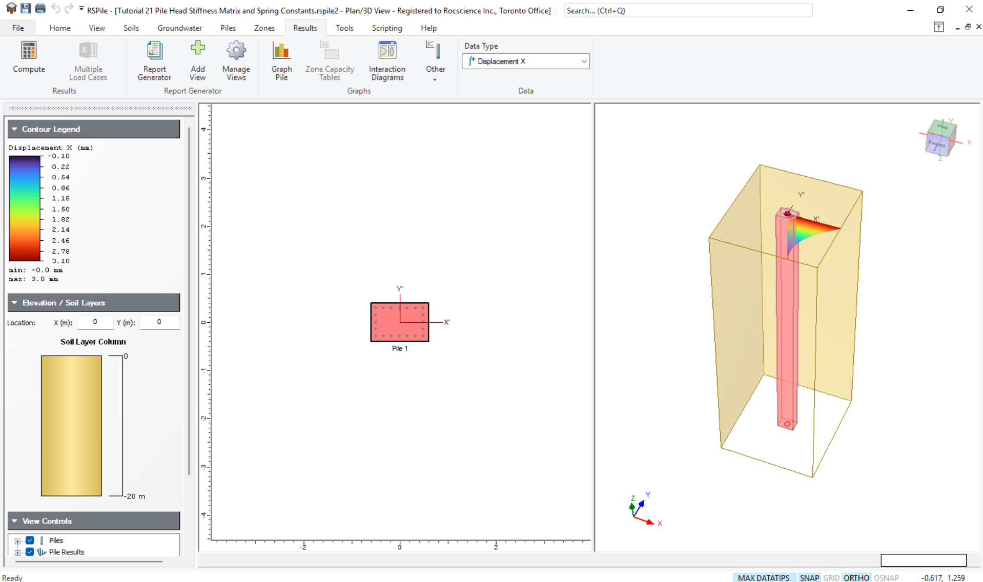
4.0 Results
After the run is finished, you can view the results for pile head stiffness matrix and your spring constants by selecting Results > Graphs > Other.
4.1 Pile Head Stiffness Matrix
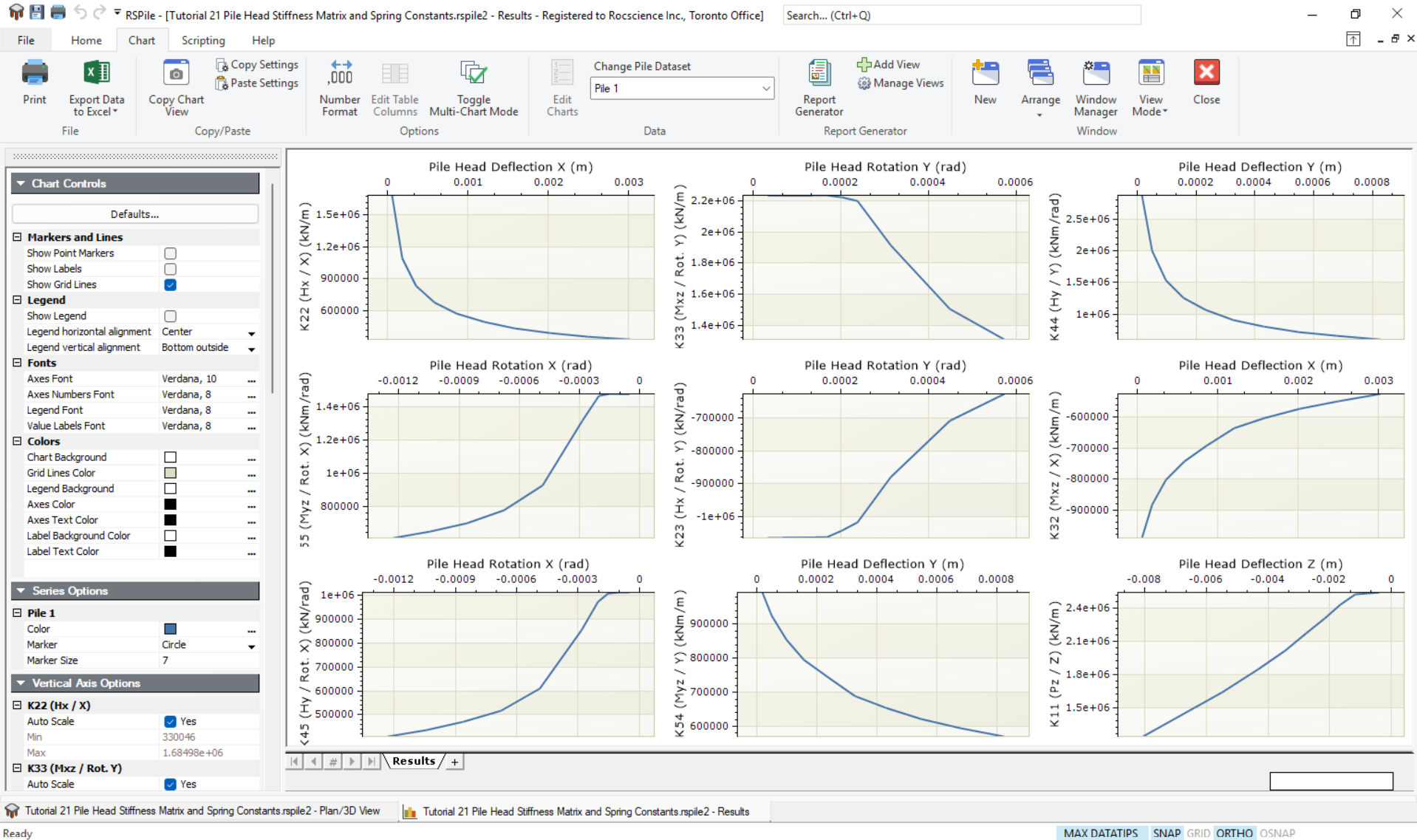
- Select Results > Graphs > Other

- Choose Pile Head Stiffness from the drop down.
- A small square cursor will appear. Put the cursor on the pile, left click to choose the pile, and press Enter.
The results will be shown as 9 graphs as follows:
The data can then be exported to an excel sheet by selecting:
- Chart > File > Export to Excel

- In the drop down, select Export Data to Excel.
The results for the nine graphs will appear in 9 sheets similar to the following:
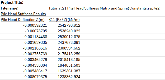
The above is for K22. There are 8 more sheets for K11, K23, K32, K33, K44, K45, K54, and K55.
4.2 Spring Constants
If simple spring constants are required, the results may be obtained the same above.
- Return to the modeller view.
- Select Results > Graphs > Other
- Choose Pile Spring Constants from the drop down.
- A small square cursor will appear. Left click to choose the pile, and press Enter.
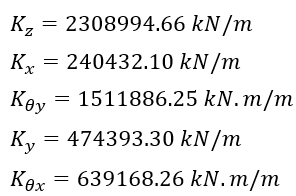
Using the same approach, we shall get 5 graphs this time:
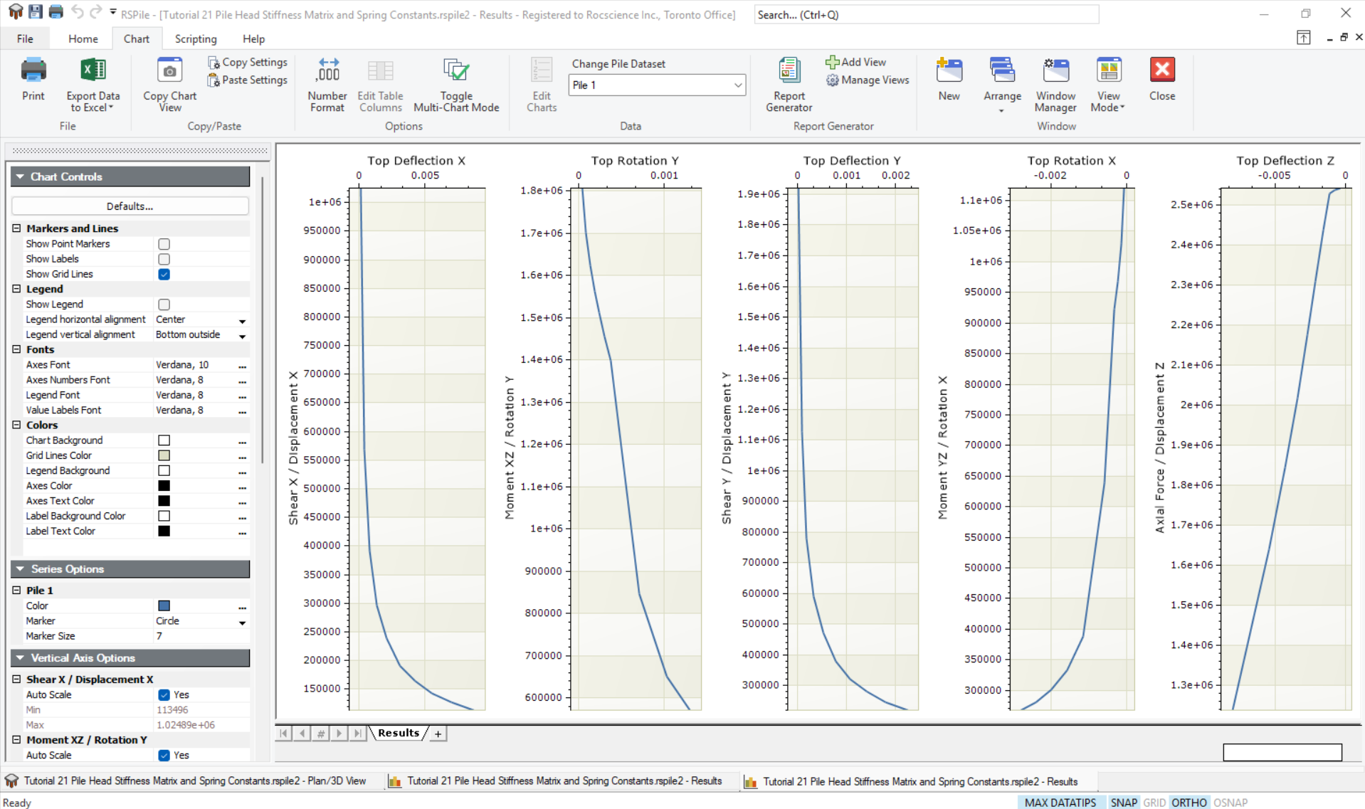
In this method the stiffness matrix is made of diagonals only. Again, you may export the data into an Excel spread sheet by selecting:
- Chart > File > Export to Excel
- In the drop down, select Export Data to Excel.
Below are the spring constants for the fifth loading step: