Design Standard
The analysis of a retaining wall is governed by the procedures stipulated in regional design standards. The following design standards are explicitly supported in RSWall:
- AASHTO LRFD Bridge Design Specifications (10th edition, 2020)
- NCMA Design Manual for Segmental Retaining Walls (3rd Edition, 2009)
- EN1997:2004 (Eurocode 7) and accompanying Eurocodes
- BS 8006-1:2010+A1:2016 (British Standard)
- AS 4678-2002 Earth-retaining structures
- User-defined design standard
Options
- View: View the design factors for the currently selected design standard
- Add: Add a new design standard based on one of the existing standards, where you can define custom factor values
- Delete: Remove a user-defined design standard from the list
- Import: Import an exported user-defined standard previous saved by this program
- Export: Export the current design standard as a separate file, which can be imported by another instance of this program (via Import)
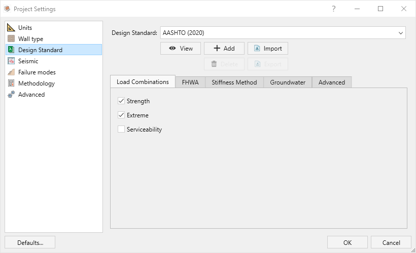
Load Combinations
Some design standards have multiple load cases and limit states that need to be considered during the analysis. By default, RSWall selects the most common cases to analyze. However, you can toggle which limit states you wish to analyze in this dialog, depending on the design standard.
If multiple limit states are selected, then analyses of the failure modes will be repeated for each limit state and all combinations of the results can be displayed.
AASHTO
Loads and resistances are factored using various combinations of the design factors defined from the columns in the tables.
- Strength - Strength limit state
- Extreme - Extreme limit state (used for seismic calculations)
- Service - Serviceability limit state (factors set to 1)
Note that AASHTO provides more in-depth list of factors in its tables in Section 3.4 (AASHTO 2020).
Eurocode
Loads and resistances are factored using various combinations of the design factors defined from the columns in the tables.
- Design Approach 1 Combination 1 - considers the factor set "A1 + M1 + R1"
- Design Approach 1 Combination 2 - considers the factor set "A2 + M2 + R1"
- Design Approach 2 - considers the factor set "A1 + M1 + R2"
- Design Approach 3 - considers the factor set "A2 + M2 + R3"
- Equilibrium - considers the factor set "EQU + R3"
- Note that during seismic analysis, the design factors listed under the "Seismic" column are assumed during the computations
(*) Note: The Equilibrium limit state is based on the "EQU" limit state defined in the Eurocode's EN1997:2004, and is typically only used when considering Overturning and other equilibrium-based failure modes.
AASHTO ASD & Eurocode ASD
RSWall also supports Allowable Stress Design (ASD) variants for AASHTO and Eurocode. In these ASD standards, all load and resistance factors are set to 1.0, so factored and unfactored values are identical. As a result, only a single load combination/load case is relevant for analysis, since all other combinations would yield the same results.
- AASHTO ASD – Based solely on the Service load case from the AASHTO LRFD framework.
- Eurocode ASD – Based solely on Design Approach 1, Combination 1 (A1 + M1 + R1).
Because only one combination is used, the Load Combinations tab is not shown for these standards. This avoids redundant output while keeping the results consistent with the governing methodology.
Australian Standard
Loads and resistances are factored using the various factors listed in Table J1 of the AS 4678.
- Load Case A - maximizes the factors on most effects
- Load Case B - maximizes some factors for some effects while minimizing the factors for favorable effects
- Load Case C - most factors set to either 1 or 0
British Standard
- Load Case A - maximizes the factors on all effects
- Load Case B - maximizes some factors for some effects while minimizing the factors for favorable effects
- Load Case C - factors set to either 1 or 0
NCMA
- The NCMA does not have limit states, but offers a seismic analysis which can be toggled via Project Settings > Seismic
Advanced Settings
AASHTO
Facing coefficient (Stiffness Method) - during the Stiffness method of calculating reinforcement tension, the value of 𝚽fs (see Allen & Bathurst, 2018).
Soil cohesion coefficient (Stiffness Method) - during the Stiffness method of calculating reinforcement tension, the value of 𝚽c (see Allen & Bathurst, 2018).
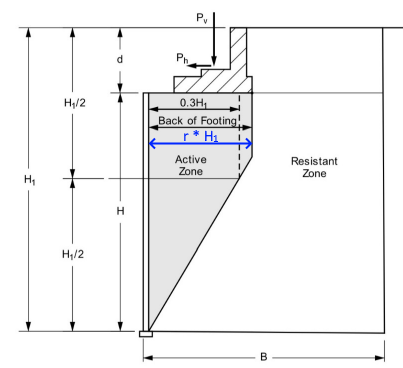
Horizontal extent of pullout zone (ratio of wall height) - the horizontal distance behind the wall, as a ratio of the total wall height, H1, for which the active zone is assumed to extent during pullout calculations. Typically it is 0.3 but it may be appropriate to extend it further if point loads exist. In other words, it is the value of r in the following diagram.
Normalized height of seismic active force - the assumed location of the seismic active force, as a ratio of the total length of the stress distribution measured from the bottom.
Change how Cwq and Cwy are calculated - During bearing capacity computations, AASHTO defines two coefficients, Cwq and Cwγ, which vary based on the anticipated position of the groundwater table to account for adjusting the effective weight of soil. You can choose for these values to either be calculated based on the effective stress in the soil, interpolated from the tables provided in AASHTO, or to select their values directly from the tables without interpolation.
Ignore the weight of wall facing during sliding calculations - neglects the contributing self-weight of the wall facing during computations of the sliding failure modes, and instead considers its area to be filled with soil to simplify the self-weight calculations.
Include the block-to-block resistance when sliding on reinforcements - when internal sliding is assessed on a reinforcement layer, keep this setting on to include the contribution of the block-to-block interface towards the total sliding resistance.
Use the hinge method - an option for using the hinge method to calculate the weight of blocks contributing to vertical stress in the wall. If it is turned off, then all the blocks above a given point will be be considered to contribute to the weight.
Ignore embedment of wall when computing bearing capacity - the term in Terzaghi's bearing capacity equation relating to the height of soil above the foundation can be conservatively ignored using this option.
Include load inclination factor for bearing capacity - the optional reduction coefficient which accounts for the relative magnitudes of horizontal and vertical loads on the foundation can be turned ON/OFF using this setting.
Use average depth of adjacent reinforcement layers when calculating Tmax - to determine the vertical stress for a given layer of reinforcement when calculating the maximum tensile force, you can either assume the actual depth of the given layer by turning this off, or assume (based on methodology from FHWA 2006; 2023) the average depth of the adjacent reinforcement layers by turning this on. Note that if this is turned on and the layer either the top or bottom layer, then the midpoint of its tributary area is taken. Note that the FHWA is typically used as a reference only and may not conform with regional requirements.
Use FHWA method when computing seismic inertial force - if this option is on, then the method for computing seismic inertial force in AASHTO is substituted with that of the FHWA (2006; 2023) methodology for seismic computations. Note that the FHWA is typically used as a reference only and may not conform with regional requirements.
Assume seismic active force acts horizontally - if this option is on, then the resultant active seismic force is assumed to act purely horizontally (based on methodology from FHWA 2006; 2023). Note that the FHWA is typically used as a reference only and may not conform with regional requirements.
F* function depth measured from ground topography - when computing the friction factor as a function of depth, the depth can be taken either as measured from the ground topography by toggling this on, or from the top of wall by toggling this off.
Ignore batter when calculating Ka - this option forces the wall's batter angle to be zero solely for the purpose of calculating the lateral pressure coefficient Ka.
NCMA
Ignore some vertical components of resisting forces and moments - in some NCMA calculations, particularly in the example computations of the 2009 edition, some vertical forces are conservatively ignored. The same forces are ignored in RSWall computations if this option is on.
Ignore interface friction during calculation of Ka - when computing the lateral earth coefficient Ka, the simplified formula is used if this option is on.
Allow negative eccentricity to be used when calculating the bearing width - according to the NCMA equations, the effective bearing width is the physical width of the base minus two times the eccentricity of loading. If the eccentricity is negative, this option allows for the effective bearing width to exceed the physical width of the base.
British Standard
Proportion of H for internal zone of maximum stress - during the Coherent Gravity method, this option defines the horizontal extent of the internal zone of maximum stress, affecting the mechanical height of the wall. It is expressed as a ratio of the total height of the wall, and typically has a value of 0.3.
Use prescribed thrust angle for active pressure - when calculating the direction of the active pressure force, the British standard adopts an empirical formula to estimate the angle. Turn this off to use theoretical values.
Include the block-to-block resistance when sliding on reinforcements - when internal sliding is assessed on a reinforcement layer, keep this setting on to include the contribution of the block-to-block interface towards the total sliding resistance.
Eurocode
Proportion of H for internal zone of maximum stress - during the Coherent Gravity method, this option defines the horizontal extent of the internal zone of maximum stress, affecting the mechanical height of the wall. It is expressed as a ratio of the total height of the wall, and typically has a value of 0.3.
Apply partial factor for friction angle also to interface friction angle - when calculating the design value of the interface friction angle, this option assumes the same partial factor for friction angles. If turned off, the interface friction angle will not be factored.
Use backfill slope angle as interface friction angle - if turned on, then sets the interface friction angle in the backfill soil to be equal to the backslope angle.
Australian Standard
Normalized height of seismic active force - the assumed location of the seismic active force, as a ratio of the total length of the stress distribution measured from the bottom.
Proportion of H for internal zone of maximum stress - during the Coherent Gravity method, this option defines the horizontal extent of the internal zone of maximum stress, affecting the mechanical height of the wall. It is expressed as a ratio of the total height of the wall, and typically has a value of 0.3.
Reduction factor to dynamic portion of seismic active force (Eac) - reduces the value of Eac by multiplying this factor during seismic computations (based on Annex I17 of AS 4678:2002)