Failure Modes
The Failure Modes tab allows you to select which failure modes are analyzed during the computations. If a failure mode is turned off, the calculations and results for the failure mode will not be shown in the results view or the report generator.
In RSWall, failure modes can be categorized under the following categories:
- External Stability - failure of the entire supporting structure.
- Internal stability - failure modes relating to internal failure within the supporting wall profile, such as through the interfaces between the internal layers of blocks.
- Reinforcement Strength - failure modes relating to the failure of the reinforcement, either in strength or in its connection with the rest of the supporting structure. In some contexts this is grouped under internal stability because the failure is internal to the supporting structure.
Failure Assessment
For each applicable failure mode that you choose to analyze, a final result - either a factor of safety or similar ratio, depending on the design standard - will be outputted in the computations.
LRFD
The AASHTO, British, Eurocode and Australian design standards are based on the Load and Resistance Factor Design (LRFD) philosophy.
- The outputted value is a ratio of the design resistance to design force, termed interchangeably as either the Capacity Demand Ratio (CDR) or Overdesign Ratio (ODR).
- LRFD factors are specified in the Design Standard tab of the Project Settings.
- A value greater 1.0 typically satisfies the design in these cases, because the loads and resistances have already been factored to account for uncertainties.
Working Stress Design
For the NCMA design standard, factors of safety are outputted since it is based on working stress design principles.
- Typically, factors of safety between 1.5 and 3 are recommended and may differ by failure mode. You can specify the allowable ratios in the Project Settings.
External Stability
These failure modes reflect the overall stability of the wall as a system.
- In general, an active soil wedge forms behind the supporting structure, and produces the primary driving force.
- The supporting structure is the wall section profile, and in the case of a reinforced wall, includes the soil within the reinforced region.
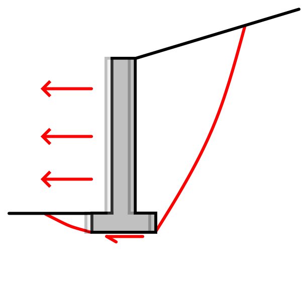
Sliding
This failure occurs by translational slipping along the base of the wall structure due to driving forces behind the wall acting parallel to the base of the wall.
- The resisting forces are typically based on the friction caused by the internal weight of the supporting structure above the base of the wall.
- If available, permanent cohesion and passive resistance from soil in the front face of the wall may contribute towards the sliding resistance, but only as permitted by the respective design standards.
- If the available resisting forces are exceeded by the driving forces then sliding failure will occur.
Note that if a leveling pad is specified in a conventional block wall, both sliding above and below the pad will be considered in the computations.
- For sliding below the leveling pad, the additional weight of the leveling pad is considered, but the active and passive zones extend to the bottom of the pad, resulting in higher active and passive forces.
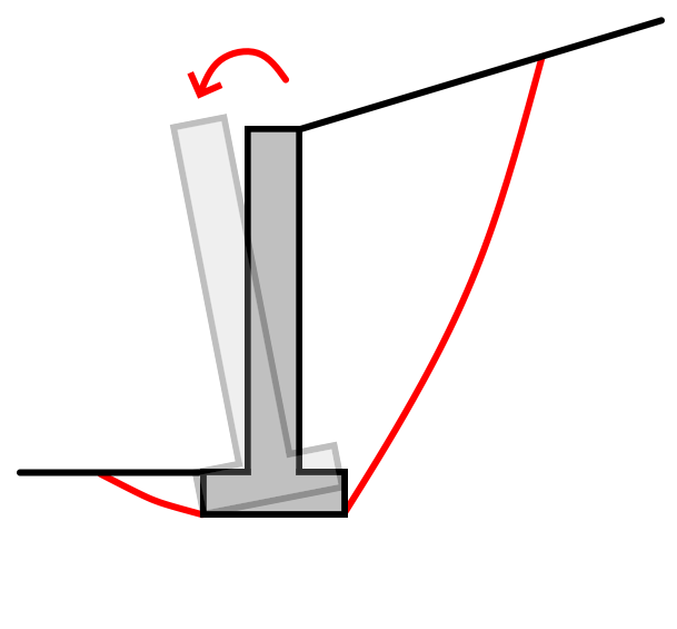
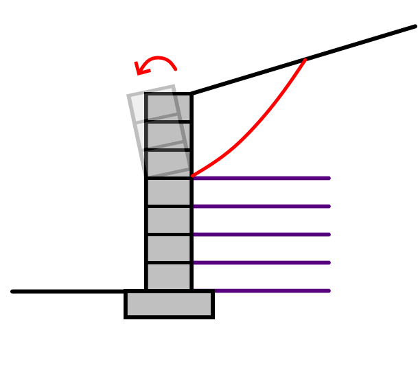
Overturning
This failure mode occurs by rotation of the wall about its toe point due to driving forces.
- The sum of driving moments (i.e. rotational actions which cause overturning) is compared against the sum of resisting moments.
- Similar to the external sliding failure mode, an active wedge is assumed when estimating the forces behind the wall.
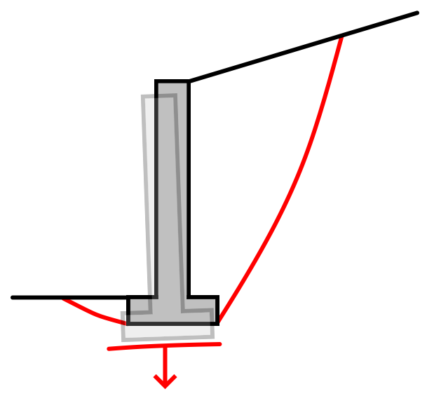
Bearing
This failure mode occurs when the bearing capacity of the foundation soil is exceeded due to excessive gravitational forces above it.
- Calculating the bearing stress involves computing the eccentricity of the resultant normal force at the base of the supporting structure, which reduces the effective bearing width of the supporting structure.
- The distribution of bearing stress along the effective bearing width depends on the design standard, and can be a function of the type of contact between the base of the wall with the foundation soil.
- If the eccentricity is too high, the width of the base may not be adequate and either a Warning or Failed Check will be produced during the computations, depending on the selected design standard.
Internal stability
These failure modes apply only for segmental and gabion walls. Note that the internal strength of concrete in the wall section profile is not within the scope of this program.
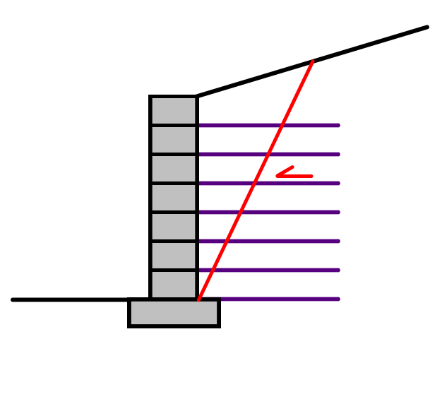
Internal sliding
This failure mode occurs by translational slipping along any of the intermediate layers of the wall.
- RSWall checks this failure mode at every layer interface of the wall section profile that has a reinforcement layer, or in the case of unreinforced segmental walls (including gabions) it is assessed at every layer.
- It is similar to the external sliding mode in that the active wedge is formed behind the supporting portion of the structure above the sliding interface, and the driving forces parallel to the sliding interface are compared against the frictional resisting forces.
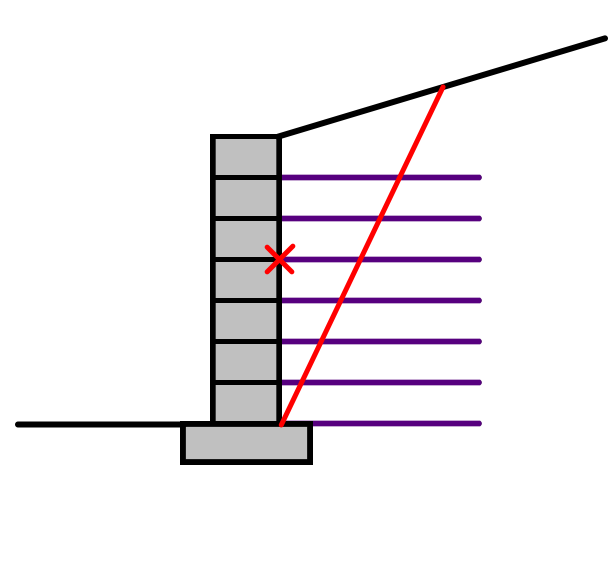
Crest toppling
This failure mode occurs by rotation of the wall about the facing point at an intermediate layer of the wall.
- It is computed in the same way as for overturning whereby the driving moments above the pivoting point are compared against the resisting moments.
- It is computed for each layer in the wall section profile that is above the highest level of reinforcement.
Reinforcement strength
These failure modes apply only for walls with reinforcements (i.e. segmental walls).
- They are technically also internal failure modes, but are made distinct from the others because they involve the reinforcements.
- They are assessed for each layer in the wall section.
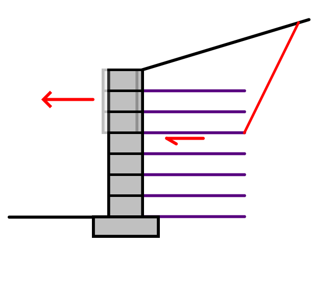
Tensile strength
This failure mode occurs by rupture of the reinforcements at any layer caused by exceeding its tensile strength.
- An active wedge forms internally causing the wall and soil within the wedge to pull outwards, resulting in tensile stresses in the reinforcements.
- The maximum tensile force can be estimated using a variety of methods available in the Project Settings.
- The available methods for determining the tensile force vary depending on the design standard, and sometimes the type of reinforcement (e.g. AASHTO does not permit use of the Coherent Gravity method for geosynthetic reinforcements).
- If these tensile stresses are exceeded then the reinforcements will fail by rupture.

Pullout strength
This failure mode occurs by detachment of the wall body along with any layer of reinforcement from the reinforced soil region.
- Similar to the assessment of tensile strength, an active wedge is assumed to form internally through the reinforcement layers, and the wall along with the soil inside the active wedge pulls outwards.
- The maximum pullout force is calculated in a similar or identical way to the maximum tensile force, depending on the design standard.
- The resisting normal stress is computed above the length of the reinforcement outside of the failure wedge, and a frictional resistance is determined.
- If the pullout force exceeds the frictional resistance then failure occurs.
Connection strength
This failure mode occurs by exceeding the connection strength at the wall facing relative to the tensile force in any layer of reinforcement.
- The connection strength can be defined in the Reinforcement Properties and may either be constant or defined to vary frictionally depending on the weight of the wall above it.
- The tensile force experienced at the location of the connection is estimated based on the various procedures stipulated in the design standards. In the worst case, it is equal to the tensile force used to evaluate tensile strength.
Other failure modes
All of the above failure modes can be checked within the RSWall program. There are some other failure modes that may need to be considered during your design.
Overall Stability
Overall or global stability failure occurs when the underlying soil fails as a result of the slope that is created by the retaining wall. You can use the Export to Slide2 feature to generate a slope stability model with the model geometry and parameters.
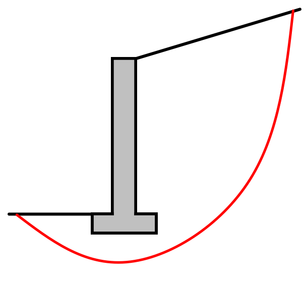
Note that RSWall does not in itself check for the global, overall or internal compound stability of the inputted wall.
Internal Compound Stability
Internal compound stability involves shear failure through the various layer interfaces in a segmental wall, with failure planes of varying shapes extending behind the facing, either through reinforcement layers or into the backfill region. This failure mode can also be analyzed by exporting the model into Slide2.
Other Failure Modes
RSWall does not check the structural integrity of the actual mass of the wall profile (e.g. structural failure of the concrete in the wall profile's structure via shear and bending moments). These failure modes typically require analysis under separate assumptions and LRFD factors under different design standards.
Various other local failure modes can exist. It is up to the designer to ensure that all required failure modes as stipulated by the design standards are accounted for.