Define Reinforcements
Users can input a database of reinforcements that they can select to include throughout their model.
To open the Define Reinforcement Properties dialog:
- Select Loading and Support > Reinforcements > Define Reinforcements

The various design standards share many parameters in common. However, some parameters will be specific to the design standard, because each one has specified a slightly different procedure for assessing the strength of a reinforcement. Only the parameters relevant to the currently selected design standard will be shown in this dialog.
Reinforcement Type
RSWall supports the following classes of supports:
- Geotextile
- Geogrid
- Geostrip
- Metallic grid
- Metallic strip
Some design standards do not provide calculation procedures for certain types of reinforcements. For example, the NCMA does not support metallic reinforcements, so those options are hidden when NCMA is the selected design standard.
Manufacturer Library
RSWall has a list of manufacturer materials, which have
specified strengths and reduction factors. You can click the Edit  button to open a list of products, upon which the parameters in the table
will be automatically filled based on your selection.
button to open a list of products, upon which the parameters in the table
will be automatically filled based on your selection.
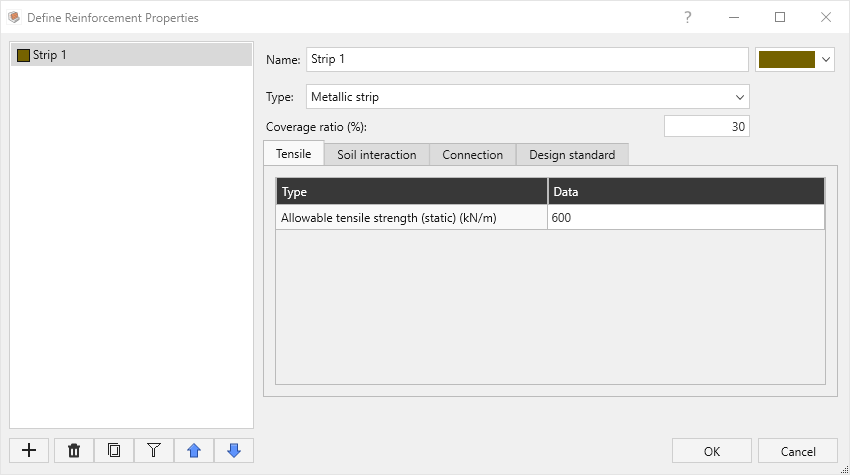
Parameters
Some reinforcements are not continuous over the length of the wall segment, but are placed at regular intervals. If the strips are not laid continuously (i.e. there are spaces between adjacent strips), then the Strip Coverage will be less than 100%. For example, if 4 meter wide strips were laid with a 2 meter spacing between each strip, then the Strip Coverage would equal 67% (i.e. 4 / (4 + 2)).
Tensile
Static design tensile strength: under static conditions, the allowable tensile strength of the reinforcement (with manufacturer factors such as the creep and installation factors applied)
Creep reduction factor: if seismic analysis is enabled, some design standards distinguish the static and seismic design tensile factors for geosynthetic reinforcements via a difference of the creep reduction factor (i.e. seismic strength = static strength * creep factor). You can specify the creep reduction factor, which will result in the seismic design tensile strength being automatically calculated based on the static value and the creep reduction factor.
Secant stiffness: if using the Stiffness Method (Allen & Bathurst 2018) of calculating tensile force in reinforcements, you can specify the individual stiffness value of the reinforcement here.
Soil Interaction
Interface sliding friction angle: (used in AASHTO and British Standard) specify the friction angle against sliding of soil along this reinforcement's material.
Pullout Method: for AASHTO analysis, you can choose either the Coefficient of Interaction or Friction Factor.
Coefficient of interaction: in this case the shear strength of the interface is defined as follows:
Where Ci is the coefficient of interaction, and c and ϕ are
the cohesion and friction angle of the material in which the
geosynthetic lies.
Friction factor function: if the Friction Factor pullout method is selected, the shear strength of the interface is defined as follows:
The friction factor input by the user is multiplied by the normal stress along the geosynthetic in order to obtain the shear strength of the interface.
You can specify a Constant value for the friction factor or define a function, F(depth), over which its value varies with depth:
- Friction factor at top: the value of F* at the top of the wall.
- Reference depth and Friction factor at reference depth: specify the value of F* at the specified depth below top of wall.
Alpha coefficient: in AASHTO, the friction factor and coefficient of interaction are further multiplied by the "α" coefficient when calculating the pullout strength.
Connection
Connection function: you can define the connection strength at the facing connection with the reinforcement layer using the following options:
- Constant: define a constant strength
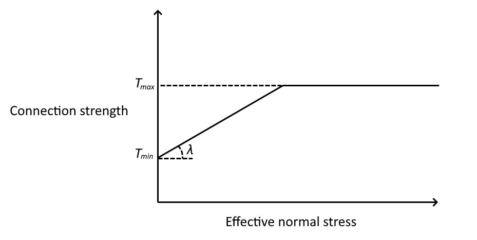
- Frictional (linear): the connection strength varies linearly as a function of the normal force, up to the maximum specified strength:
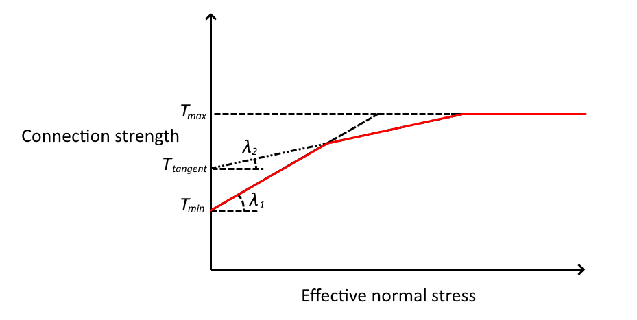
- Frictional (bilinear): the connection strength varies linearly as a minimum of two linear functions, up to the maximum specified strength:
- F(depth): the connection strength varies between the minimum strength (at the top of the wall) and increases by the rate of Change per unit depth specified up to the maximum specified strength.
Design standard
- Lists the partial factors or LRFD factors that apply to this reinforcement, which will be used in the computations.
- Some of these may not be editable because their values are prescribed directly in the design standard.