1 - MSE Wall
In this tutorial, a Mechanically Stabilized Earth (MSE) wall is designed using the AASHTO 2020 standard. A step-by-step guide through the design process is provided.
Topics Covered:
- MSE Wall Design
- Single Panel Wall
- Defining Soil Properties and Properties
- Loading and Support
- Overall Stability Analysis in Slide2
Finished Product:
The finished product of this tutorial can be found in the Tutorial 1 folder. All tutorial files installed with RSWall can be accessed by selecting File > Recent Folders > Tutorials Folder from the RSWall main menu.
1.0 Getting Started
This section will cover starting a new project and configuring the project settings.
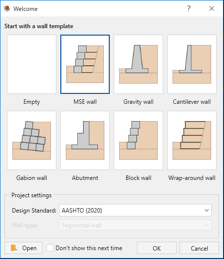
- Open RSWall and select MSE wall from the wall template options.
- For Design Standard select AASHTO 2020.
- Click OK.
2.0 Project Settings
- Select Home > Project > Project Settings
 from the toolbar.
 - In the Units
 tab, select Imperial, stress as psf.
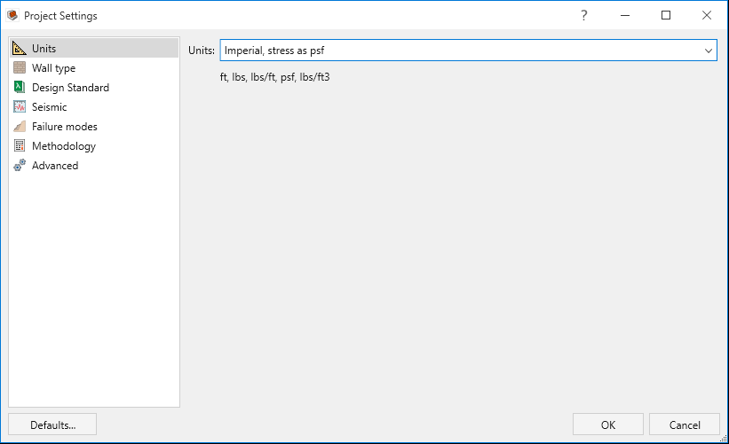
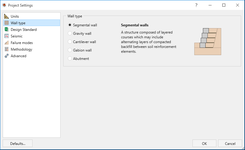
- Select the Wall type
 tab.
tab. - Segmental wall is selected by default
- Segmental wall is selected by default
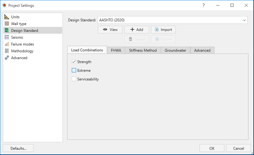
- Select the Design Standard
 tab.
tab. - Ensure AASHTO 2020 is selected. In the Load Combinations section,
deselect Extreme and Serviceability so that only Strength is
selected.
- Ensure AASHTO 2020 is selected. In the Load Combinations section,
deselect Extreme and Serviceability so that only Strength is
selected.
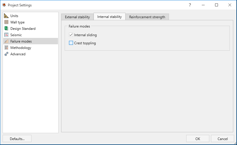
- Select the Failure modes
 tab.
tab. - Select the Internal stability
menu and deselect Crest toppling.
- Select the Internal stability
menu and deselect Crest toppling.
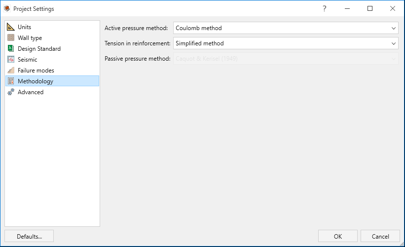
- Select the Methodology
 tab.
tab.- Set the Active pressure method to Coulomb method.
- Set the Tension in reinforcement
to Simplified method.
- Select OK to apply your changes.
3.0 Wall
In this section we will define the wall profile.
- Go to the Wall ribbon.
- Select Wall > Wall Profile > Define Wall Units
 from the
toolbar.
from the
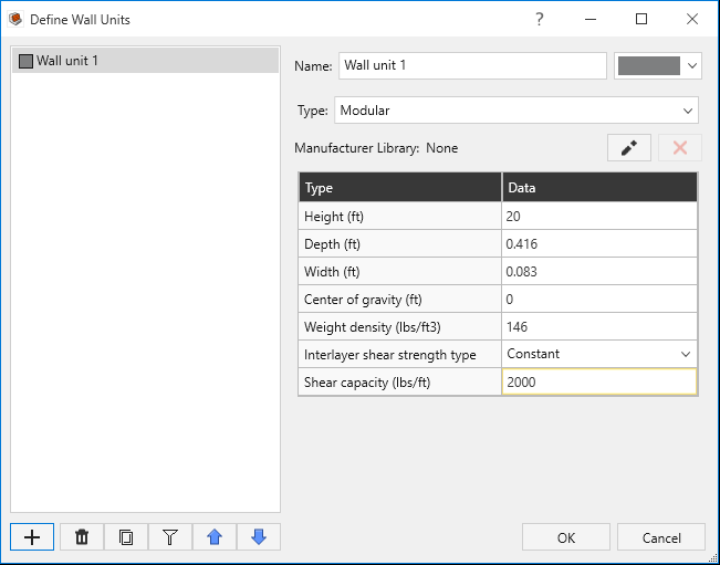
toolbar. - In the Define Wall Units dialog, edit the parameters for Wall Unit 1 as follows:
- Height (ft) = 20
- Depth (ft) = 0.4
- Width (ft) = 0.1
- Center of gravity (ft) = 0
- Weight Density (lbs/ft3) = 146
- Interlayer shear strength type = Constant
- Shear capacity (lbs/ft) = 2000
- Click OK to apply your changes and close the dialog.
- Select Wall > Wall Profile > Define Section Profile
 from the toolbar.
 - In the Define Section Profiles
dialog, change the following parameters of Profile 1:
- Set Number of wall courses = 1.
- Select Wall layer arrangement = Batter angle (degrees) and enter Batter angle (degrees) = 3.
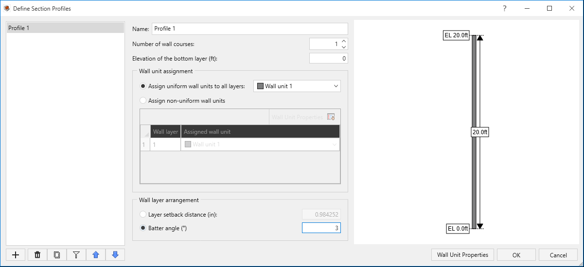
- Select OK.
- Select Wall > Single Segment Wall > Edit
 from the toolbar.
- In the Edit Wall dialog, you can see that a 20ft wall is created. Click OK to close the dialog.
- Select Wall > Base > Add Leveling Pad
 from the toolbar.
 - In the Add Leveling Pad
dialog, select the Add leveling pad checkbox and add the following dimensions:
- Thickness (in) = 6
- Width (ft) = 3
- Setback (in) = 3
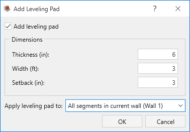
- Click OK.
- Select Wall > Base > Define Base Strength
 from the toolbar.
- Set Contact with soil = Soil on soil.
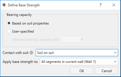
- Set Contact with soil = Soil on soil.
- Click OK.
4.0 Soil
In this section we will define the soil properties and assign them to different regions.
- Go to the Soil ribbon.
- Select Soil > Soil Geometry > Backslope Topography
 in the
toolbar.
in the
toolbar. - In the Backslope Topography
dialog, set the Terrain profile to Broken. Under Geometry, define
a 26.6o backslope as follows:
- Initial run (ft) = 0
- Slope run (ft) = 18
- Slope angle (°) = 26.6
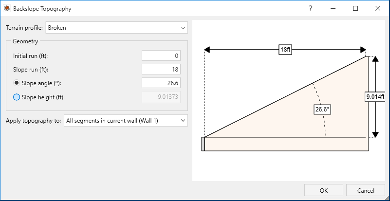
- Click OK to apply your changes and close the dialog.
- Select Soil > Soil Geometry > Front Face Topography
 in the toolbar.
 - In the Front Face Topography
dialog, set the Embedment depth (ft) = 3.
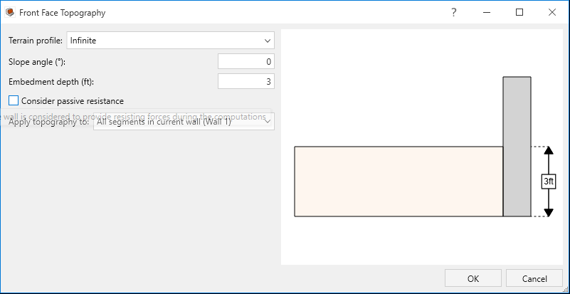
- Click OK.
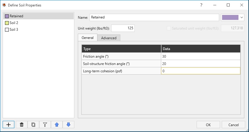
- Select Soil > Soil Conditions > Define Soil Properties
 in the toolbar.
 - In the Define Soil Properties dialog, add the following soil properties as they are defined in the table below:
- Click OK.
- Select Soil > Soil Conditions > Assign Soil Properties
 in the toolbar.
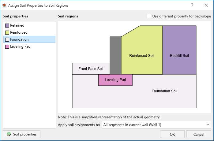
 - The Assign Soil Properties to Soil Regions dialog will open. To assign a soil
property to a region:
- Select the desired soil property from the left-hand menu.
- Click the desired region on the diagram to assign the property. You will see the region’s color change to correspond with the selected soil property.
- Assign the matching soil properties to the soil regions as follows:
- Front Face Soil = Foundation soil property.
- Reinforced Soil = Reinforced soil property.
- Backfill Soil = Retained soil property.
- Foundation Soil = Foundation soil property.
- Leveling Pad = Leveling Pad soil property.
- Click OK.
| Soil name\Property | Unit Weight (ld/ft3) | Friction Angle (o) | Soil-Structure friction Angle (o) | Long-term cohesion (psf) |
|---|---|---|---|---|
Retained |
125 |
30 | 20 | 0 |
Reinforced |
130 |
34 | 22 | 0 |
Foundation |
125 |
30 | 20 | 0 |
Leveling Pad |
150 |
40 | 27 | 200 |
5.0 Loading and Support
In this section we will define a live load, as well as our reinforcement properties and arrangement.
- Go to the Loading and Support ribbon.
- Select Loading and Support > Loads > Manage Loads
 from the toolbar.
 - In the Manage Loads dialog:
- Set Magnitude (psf) = 250
- Set Horizontal distance (ft) = 18
- Select the Assigned Segments tab and assign the load to Segment 1.
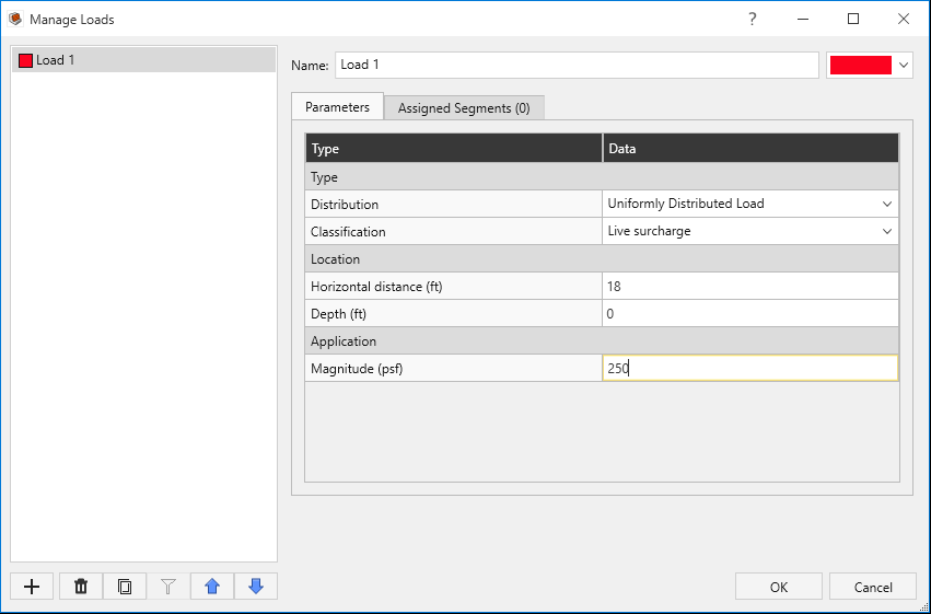
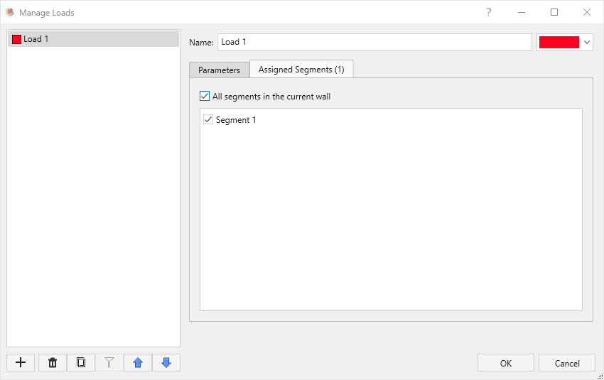
- Click OK to apply your changes and close the dialog.
- Select Loading and Support > Reinforcement > Define Properties
 in the toolbar.
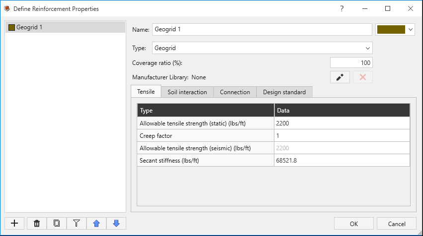
 - In the Define Reinforcement Properties
dialog, add Geogrid 1 and Geogrid 2 and change Type to Geogrid for both. Define the support properties with the parameters in
the following tables (coverage ratio for both supports is 100%):
- Tensile tab:
Name\Properties Allowable tensile strength (static) (lbs/ft) Geogrid 1
2200
Geogrid 2
2500
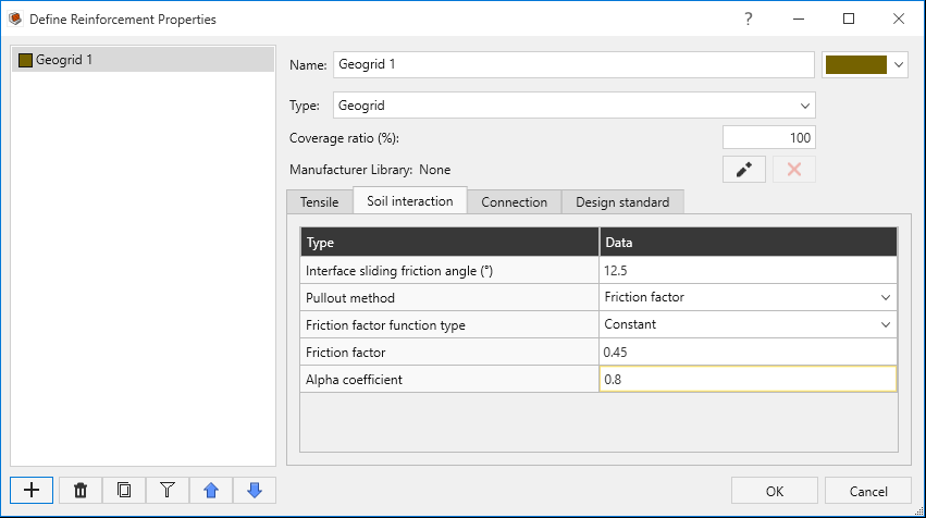
- Soil Interaction tab:
Name\Property Interface sliding friction angle (o) Pullout method
Friction Factor function type Friction factor Alpha Coefficient Geogrid 1
12.5 Friction factor Constant 0.45 0.8
Geogrid 2
15 Friction factor Constant 0.45 0.8
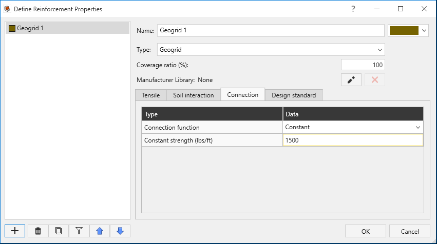
- Connection tab:
Name\Property Connection function Connection strength (lb/ft) Geogrid 1
Constant 1500
Geogrid 2
Constant 1800
- Tensile tab:
- Click OK.
- Select Loading and Support > Reinforcement > Add Layout
 from the toolbar.
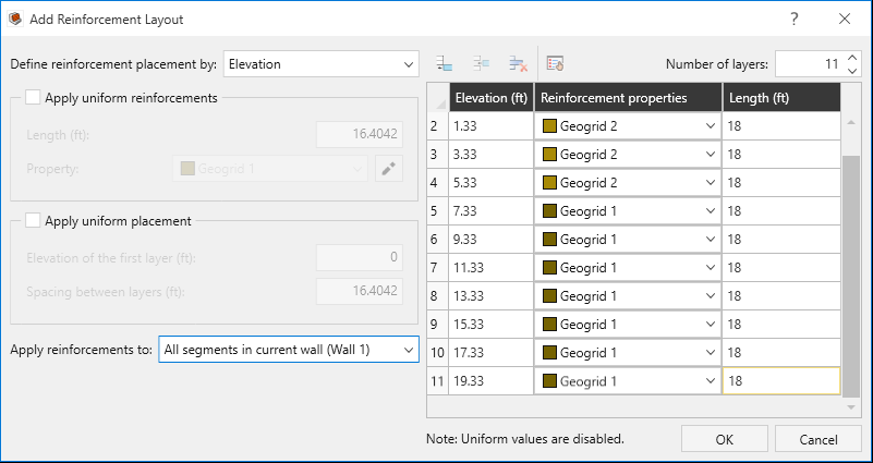
 - In the Add Reinforcement Layout
dialog:
- Set Define reinforcement placement by = Elevation.
- Set Length (ft) = 18 for row 1.
- Set Number of layers = 11. The data from row 1 will be copied to the additional rows.
- Use the table below to edit the properties of each row (every row’s
Length = 18):
Layer Elevation (ft) Reinforcement Properties 1
0.67
Geogrid 2
2
1.33
Geogrid 2
3
3.33
Geogrid 2
4
5.33
Geogrid 2
5
7.33
Geogrid 1
6
9.33
Geogrid 1
7
11.33
Geogrid 1
8
13.33
Geogrid 1
9
15.33
Geogrid 1
10
17.33
Geogrid 1
11
19.33
Geogrid 1
- Click OK.
- Select Home > File > Save > Save As
 and save the model as “Tutorial 1”.
6.0 Results
In this section, we will compute the analysis and review the results.
- Go to the Results ribbon.
- Select Results > Compute > Compute
in the toolbar.
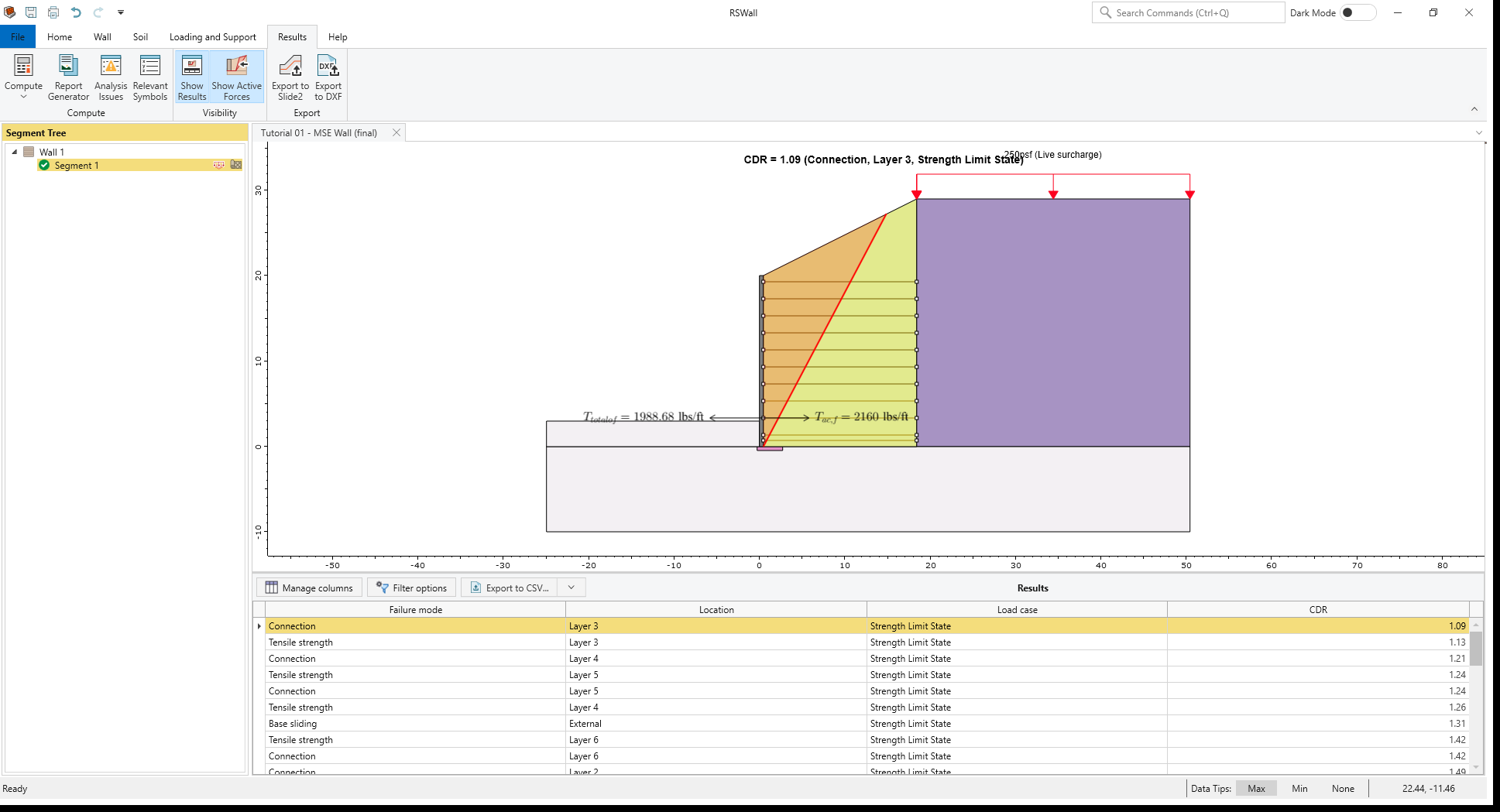
- After the computation is complete, the results will appear onscreen:
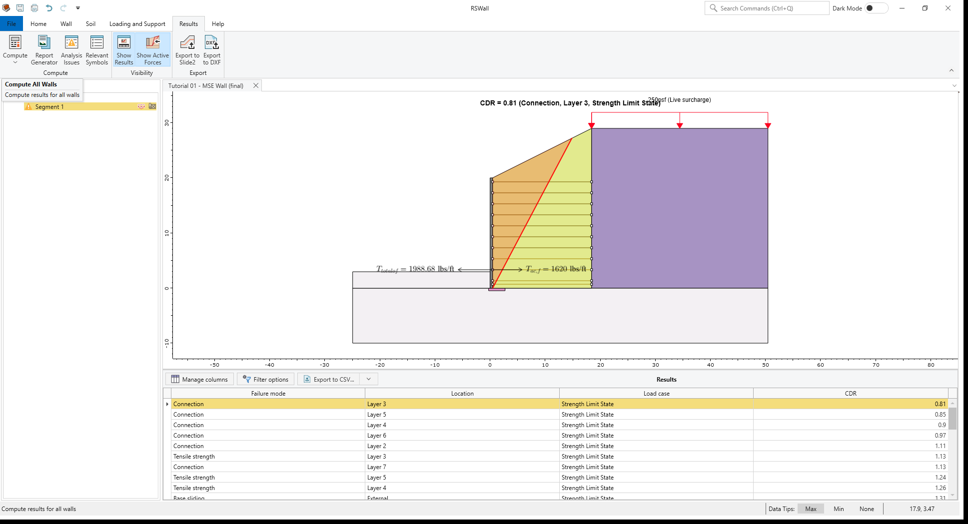
- The software shows the lowest Capacity Demand Ratio (CDR) value, which for this example is for the Connection failure
mode and Layer 3. The forces for this layer are shown on the model.
The table at the bottom of the program can be sorted by Failure mode, Location, Load case or CDR. Select any of these options to sort the table based on their order. In the table, go to the Filter Options and select Sliding, Overturning and Bearing. The table shows that all these modes have a CDR of above 1.3.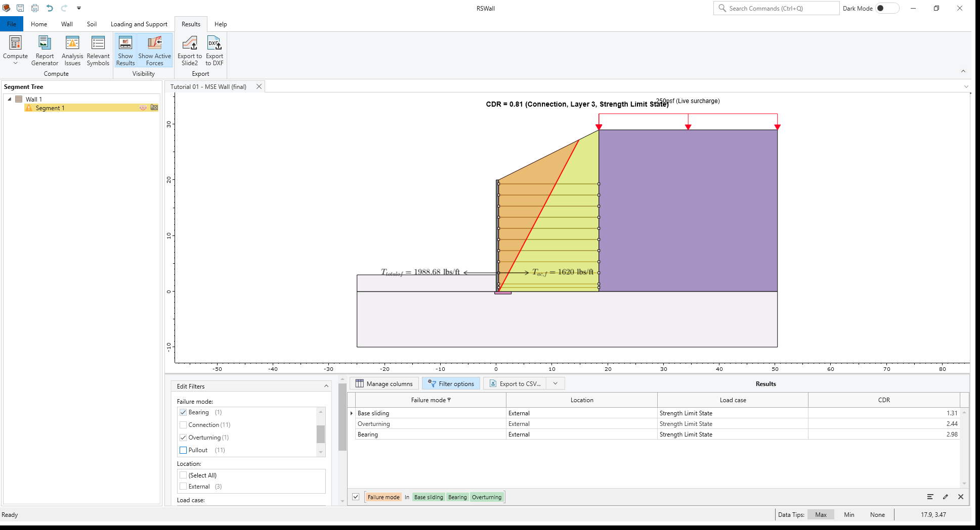
- Now select Tensile Strength only. You can see the tensile strength per layer.
You can double click on any row of the table to view the forces on the model.

- In the Segment Tree, there is a warning icon beside Segment 1. This means that the
Analysis Issues
dialog should be reviewed. Select Results > Compute > Analysis Issues
 from the toolbar to open this dialog.
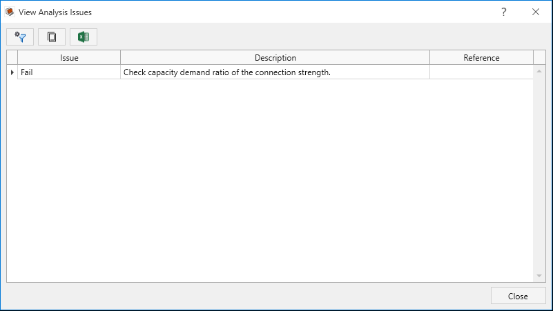
- In the Analysis Issues dialog, you will see that some reinforcement layers have failed in
connection (the results table indicates that layers 3-6 have failed in connection). Click Close to
close the dialog.
- Select Loading and Support > Reinforcements > Define Properties in the toolbar.
- In the Define Reinforcement Properties dialog, change the Connection strength
for each Geogrid to the following, then select OK:
- Geogrid 1: Connection strength (lbs/ft) = 2200
- Geogrid 2: Connection strength (lbs/ft) = 2400
- Select Results > Compute > Compute again. The icon beside the Segment 1 in the Segment
Tree is green now.
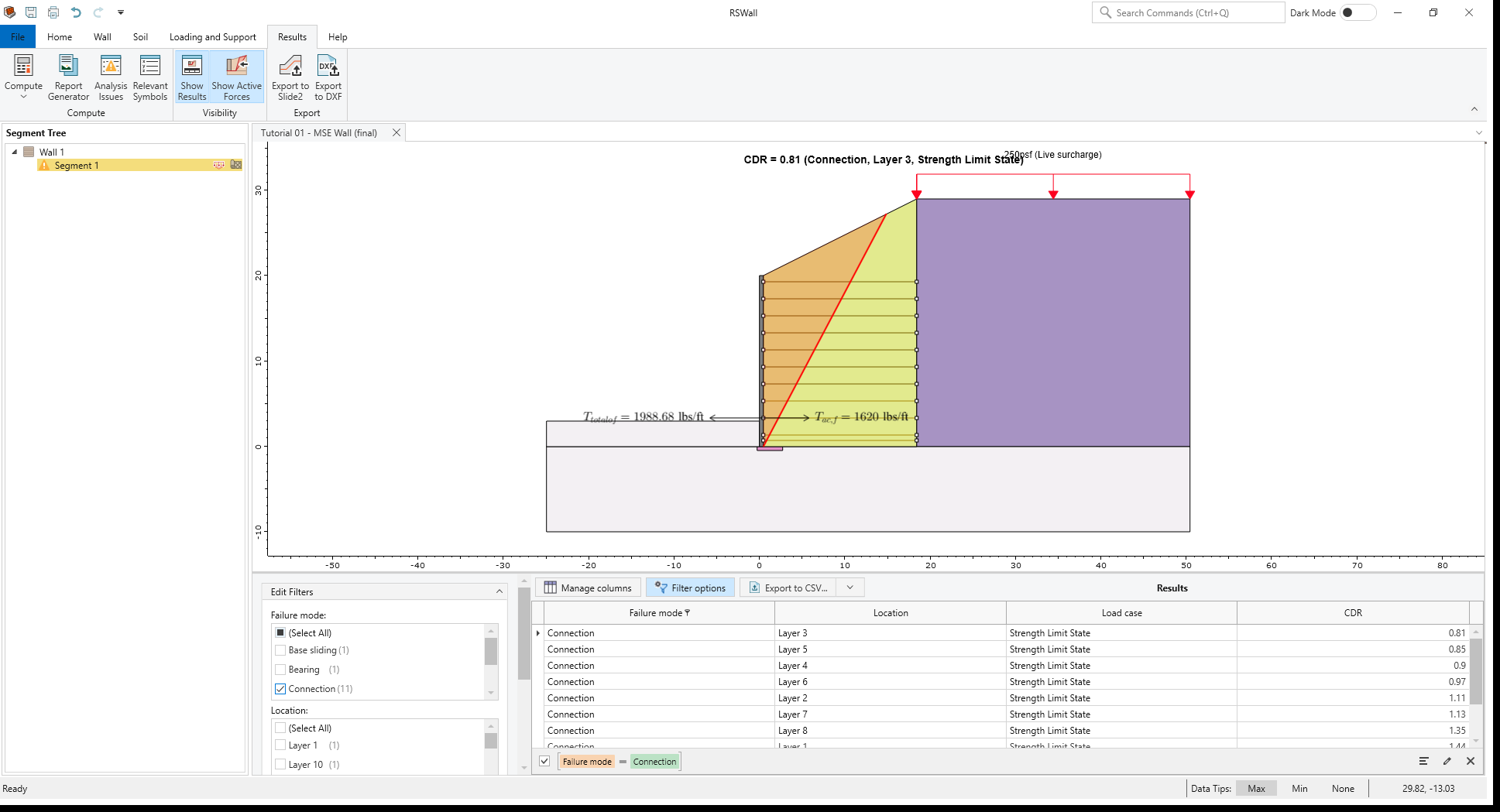
- Select Filter Options to open the Edit Filters side tab. Under Failure mode, select Connection and under Location, select Layers 3 to 6. You can see in the table that the factor of safety for these layers are above 1 and they don’t fail in connection.
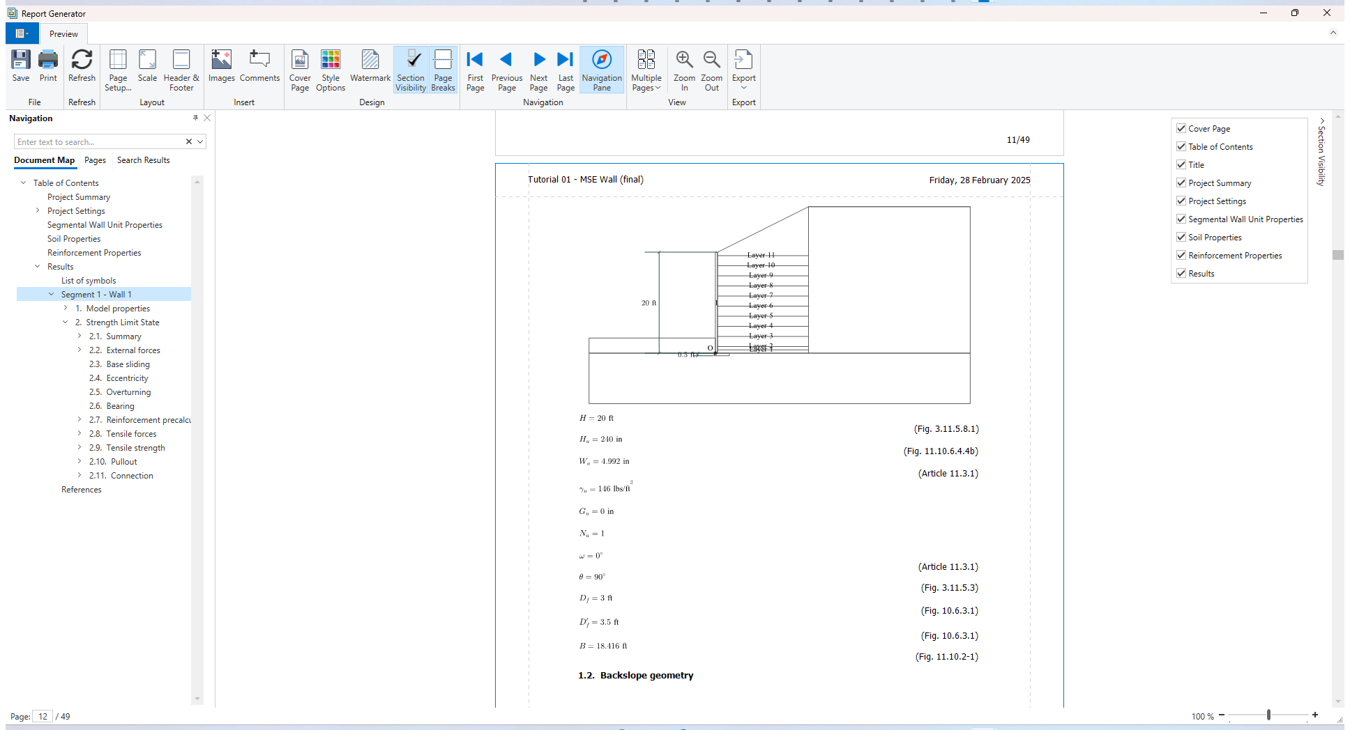
- Select Results > Compute > Report Generator
 in the toolbar. The Report
Generator in RSWall provides all the hand calculations for the output results of the RSWall program.
in the toolbar. The Report
Generator in RSWall provides all the hand calculations for the output results of the RSWall program. - Under Navigation, click on the Results section. At the beginning of the section, the List of symbols used in the analysis is provided.
- Select Segment 1 > Model properties. A summary of calculations and
detailed hand calculation for each failure mode is provided.
- Close the Report Generator.
7.0 Slide2 Overall Stability Analysis
This section will cover exporting the RSWall project to Slide2 and conducting a stability analysis.
- Select Results > Export > Export to Slide2
 in the toolbar.
 - In the Export to Slide2 dialog, select Segment 1 then click Open in Slide2.
- Once the file opens in Slide2, select File > Save As
 and save the Slide2 file as “Segment 1”.
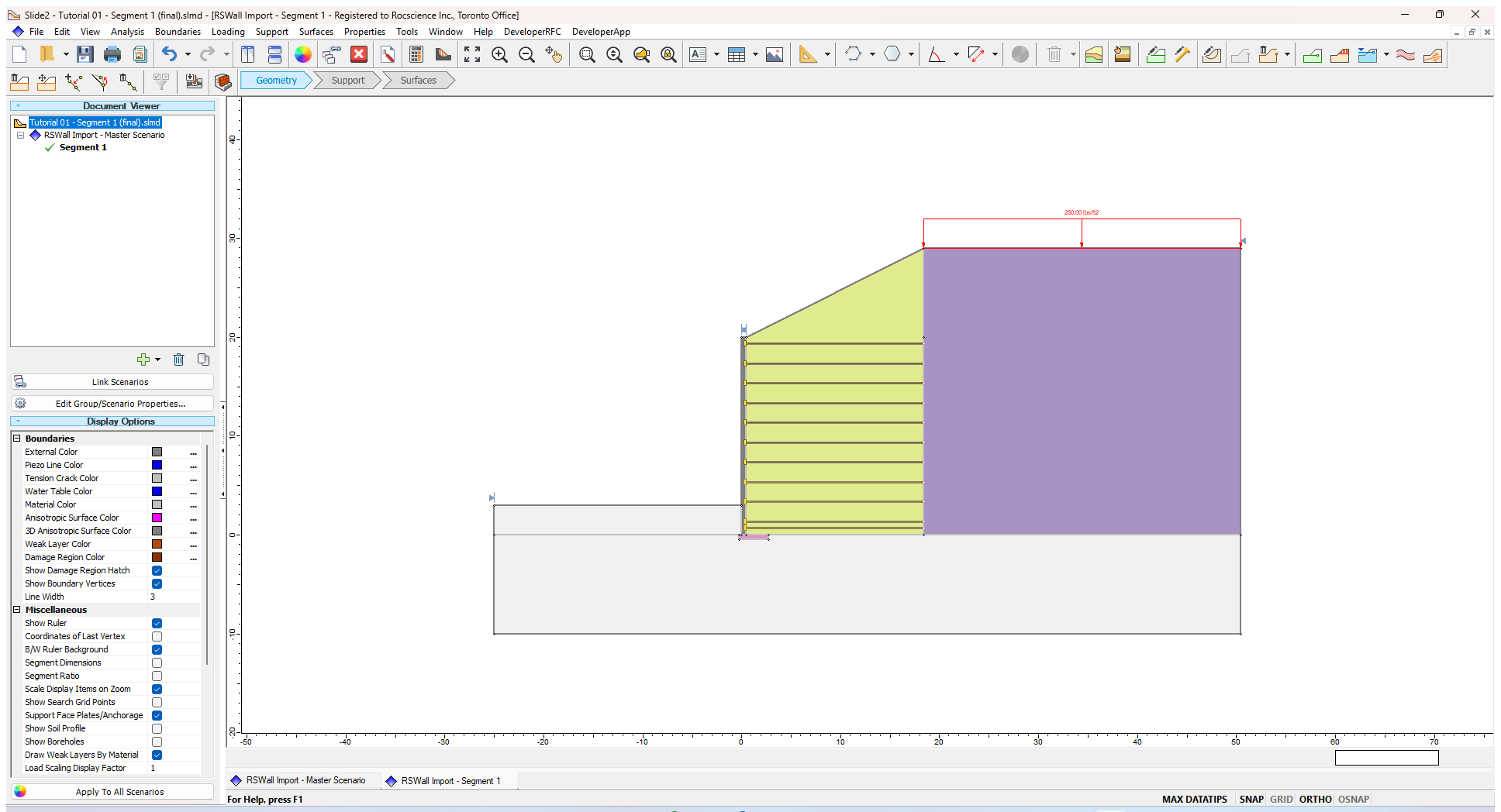
- Select Analysis > Compute

- Once the file is computed, select Analysis > Interpret
 .
. - The result is shown as below:
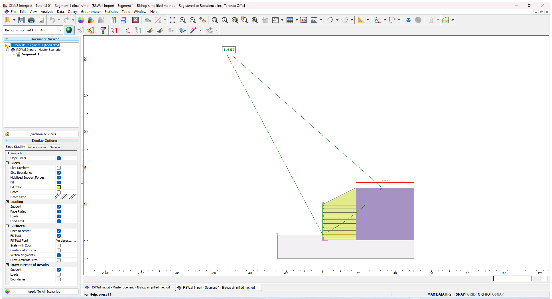
- It can be seen in this model that the factor of safety using the Circular Bishop method is 1.4, or, the overall stability analysis and the failure surface goes behind the support zone (external failure).
This concludes Tutorial 1.