2 - Multi-Segmental Wall
In this tutorial, a Multi-Segmental wall is designed in RSWall using the AASHTO 2024 standard. A step-by-step design process is provided.
Topics Covered:
- Multi-Segment Wall Design
- Manufacturer Library
- Wall Wizard
- Overall Slide2 Stability Analysis
Finished Product:
The finished product of this tutorial can be found in the Tutorial 2 folder. All tutorial files installed with RSWall can be accessed by selecting File > Recent Folders > Tutorials Folder from the RSWall main menu.
1.0 Getting Started
- Open the RSWall program.
- Select an empty project from the wall template options.
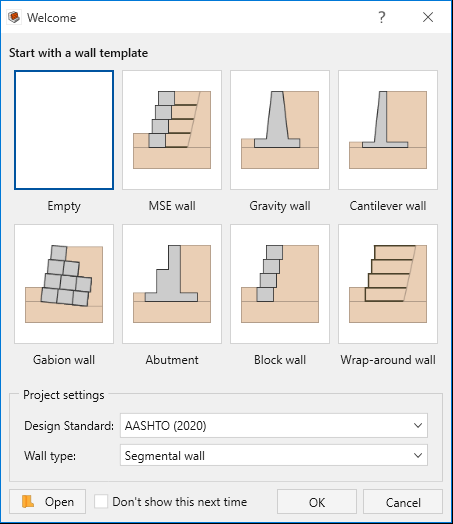
- Click OK.
2.0 Project Settings
- Go the Home ribbon and select Home > Project > Project Settings

- In the Units
 tab, confirm that the Units are set to Metric, stress as
kPa.
tab, confirm that the Units are set to Metric, stress as
kPa. - Select the Wall type
 tab. Confirm that Wall type is set to Segmental
wall.
tab. Confirm that Wall type is set to Segmental
wall.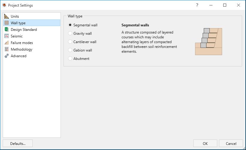
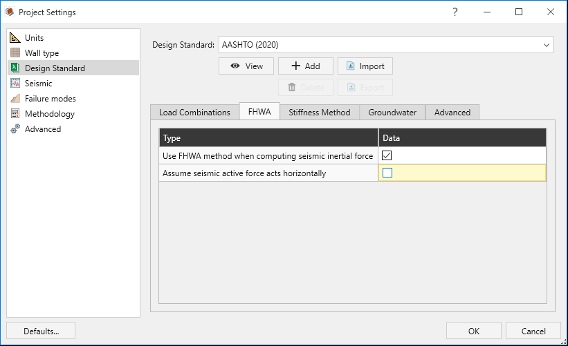
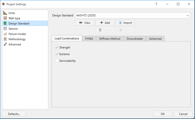
- Select the Design Standard
 tab.
tab. - Confirm that the design standard is set to AASHTO (2024), and that Strength and Extreme are toggled on under the Load Combinations options.
- Select the FHWA tab, and tick the checkbox for Use FHWA method when computing seismic inertial force.
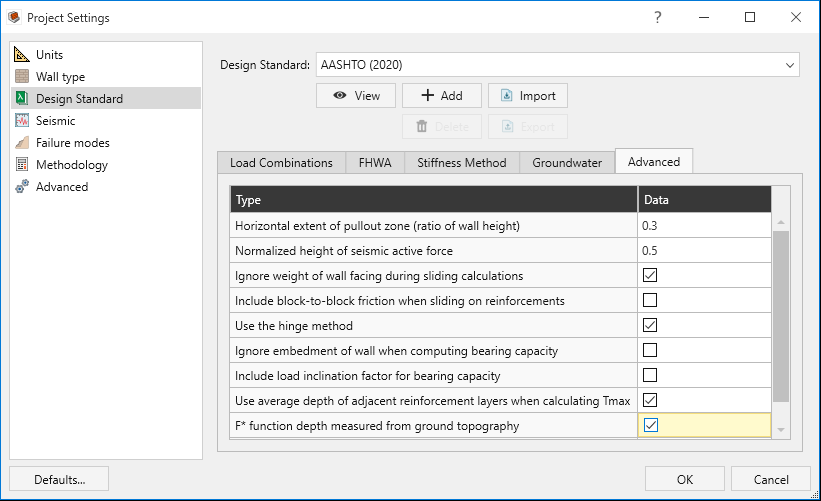
- Select the Advanced tab.
- Select the Ignore weight of wall facing during sliding calculations checkbox.
- Select the Use average depth of adjacent reinforcement layers when calculating Tmax
checkbox.
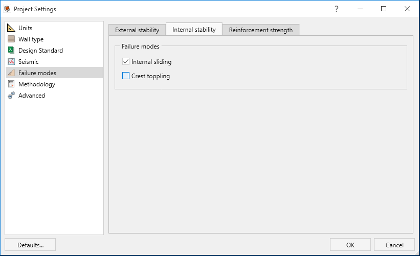
- Select the Failure modes
 tab.
tab. - Select the Internal stability
settings tab and deselect Crest toppling.
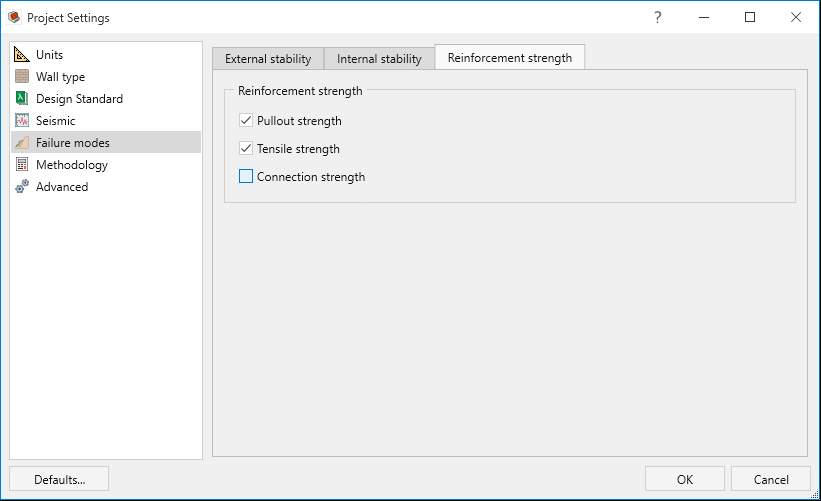
- Select the Reinforcement strength settings tab and deselect Connection
strength.
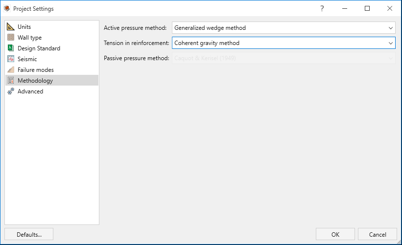
- Select the Methodology
 tab. Select the following:
 - Active pressure method = Generalized wedge method.
- Tension in reinforcement = Coherent gravity method.
- Click OK to apply the changes and close the dialog.
3.0 Wall Units
In this section, we define the wall units of the model.
- Go to the Wall ribbon.
- Select Wall > Wall Profile > Define Wall Units

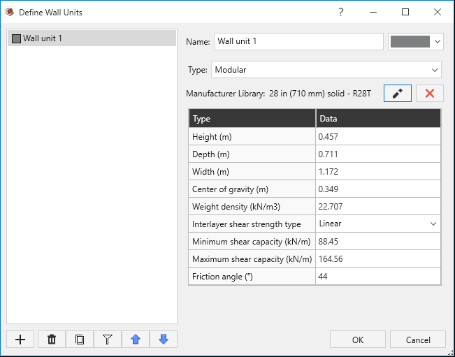
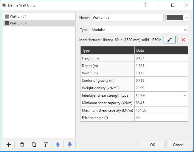
- In the Define Wall Units dialog, add a new wall unit using the +Add button.
- Add a Manufacturer Library to both Wall unit 1 and Wall unit 2 as shown below:
- Click on the
 button next to Manufacturer Library.
 - Set Manufacturer = RediRock for both wall units.
- For Wall Unit 1, under Blocks, select 28 in (710 mm) solid – R28T.
- For Wall Unit 2, under Blocks, select 60 in (1520 mm) solid – R60M.
- Click OK to close the Define Wall Units dialog.
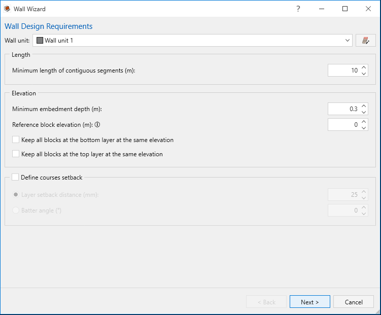
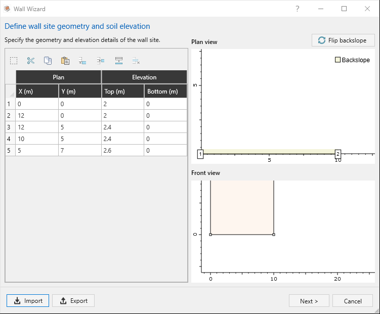
- Select Wall > Multi-Segment Wall > Wizard

- In the Wall Wizard dialog:
- Select the Import button.
- Import PlanElevationPoints.txt from the tutorial folder.
- Click OK in the Import CSV File dialog.
- Click Next in the Wall Wizard dialog.
- Click Next again. The last window shows the Wall Front view and Plan
view of the selected segment.
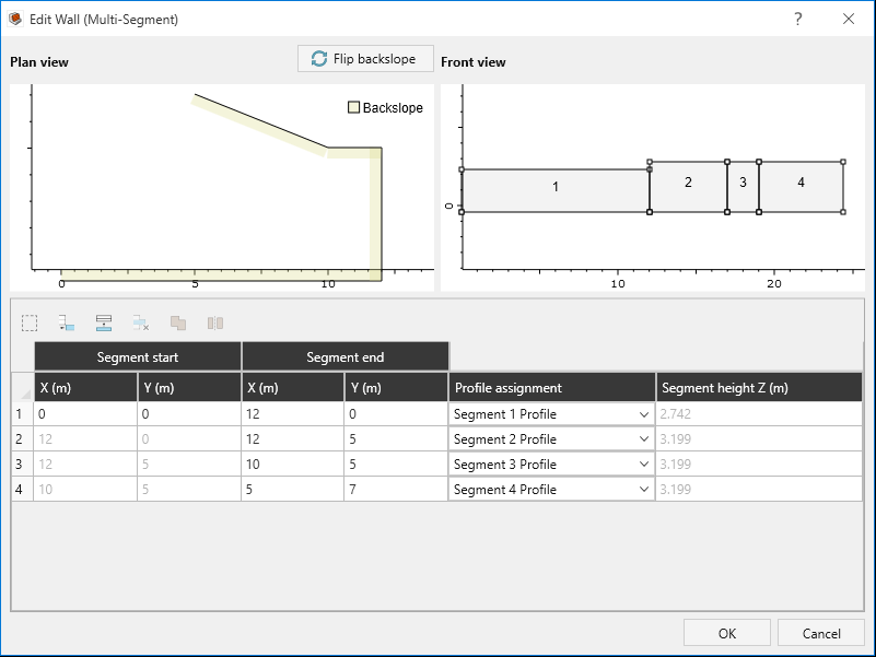
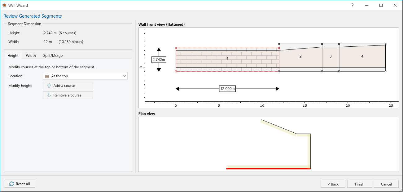 In this dialog you can make changes to each segment by adding and removing courses to the top and bottom of the segments or to the left and right of the segments. Also, other options such as splitting and merging segments are available.The segment heights are always equal to the highest elevation of the soil profile behind that segment.
 - Click Finish. You will see that multiple segments are created.
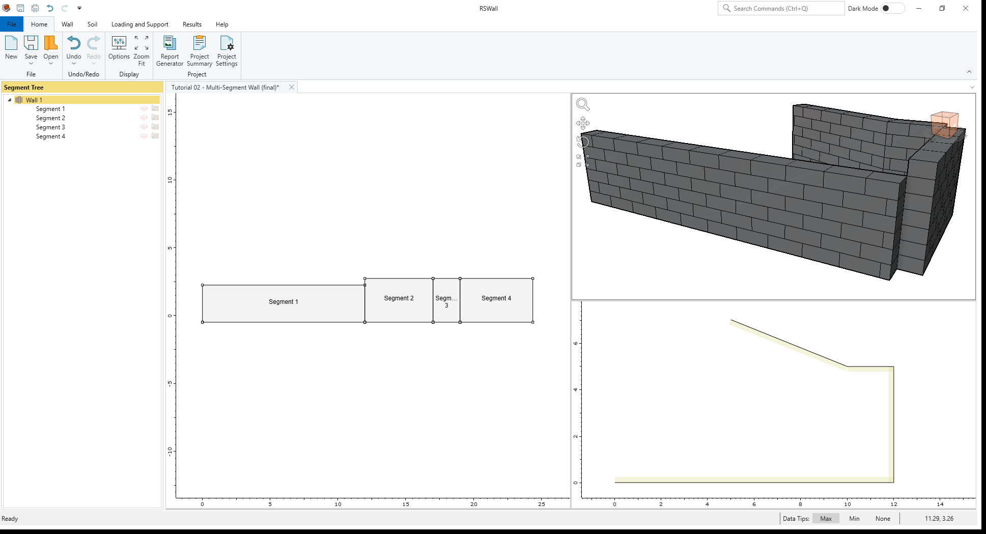
To edit segment coordinates, you can always:
- Select Wall > Multi-Segment Wall > Edit
 .
.
4.0 Section Profile
In this section, we will cover defining the wall section profile.
- Select Wall > Wall Profile > Define Section Profile
 in the toolbar. Assign the following
wall courses and Wall units (using the Assign uniform wall units to all layers
option) to the segment profiles:
in the toolbar. Assign the following
wall courses and Wall units (using the Assign uniform wall units to all layers
option) to the segment profiles: - Segment 1 Profile: 6 wall courses and Wall unit 1
- Segment 2 Profile: 7 wall courses and Wall unit 1
- Segment 3 Profile: 7 wall courses and Wall unit 1
- Segment 4 Profile: 8 wall courses and Wall unit 2
- Click OK to apply the changes and close the Define Section Profiles dialog.
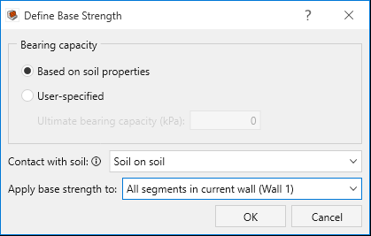
- Click on a segment from the Segment Tree, then select Wall > Base > Define Base
Strength

- Set Contact with soil = Soil on soil.
- Set Apply base strength to = All segments in current wall (Wall 1)
- Click OK to close the dialog.
5.0 Soil
In this step we define the soil properties, and we assign them to different regions.
- Go to the Soil ribbon.
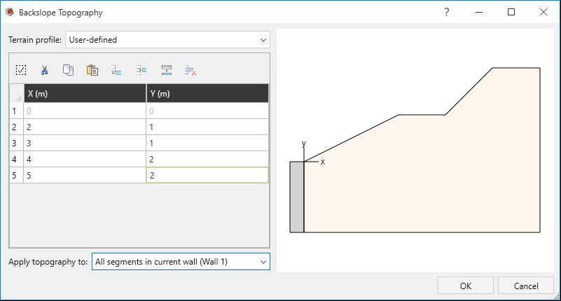
- Select Soil > Soil Geometry > Backslope Topography

- In the Backslope Topography dialog, set the Terrain Profile = User defined.
- Add 4 rows to the table and enter the following coordinates:
- X: 2, Y: 1
- X: 3, Y: 1
- X: 4, Y: 2
- X:5, Y: 2
- Click OK and close the Backslope Topography dialog.
- Select Soil > Soil Geometry > Front Face Topography

- In the front Face Topography dialog, enter:
- Terrain profile = Infinite
- Embedment depth (m) = 0.4 m
- Click OK to close the dialog.
- Select Soil > Soil Conditions > Define Soil Properties

- In the Define Soil Properties dialog, define soil properties according to the following table:
- Click OK to close the Define Soil Properties dialog.
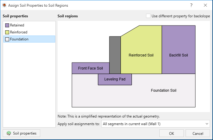
- Select Soil > Soil Conditions > Assign Soil Properties

- In the Assign Soil Properties to Soil Regions dialog, assign the properties as follows by selecting a soil property and then clicking on a desired soil region:
- Reinforced Soil: Reinforced soil property
- Backfill Soil: Retained soil property
- Leveling Pad: Retained soil property
- Front Face Soil: Retained soil property
- Foundation Soil: Foundation soil property
- Click OK to close the dialog.
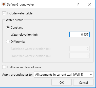
- Select Soil > Groundwater > Define Groundwater

- In the Define Groundwater dialog:
- Select Include water table to enable the water parameters.
- Under Water Profile, select Constant and set the Water elevation (m) = -0.457.
- Click OK apply your changes and close the dialog.
| Soil Name/Property | Unit Weight (kN/m3) | Friction Angle (o) | Soil-Structure friction Angle (o) | Long-term cohesion (psf) |
|---|---|---|---|---|
Retained |
20 |
30 | 20 | 8 |
Reinforced |
22 |
34 | 26.5 | 0 |
Foundation |
23 |
34 |
20 | 0 |
6.0 Loading and Support
In the Loading and Support ribbon, we will define a live load and our reinforcement properties and arrangement.
- Go to the Loading and Support ribbon.
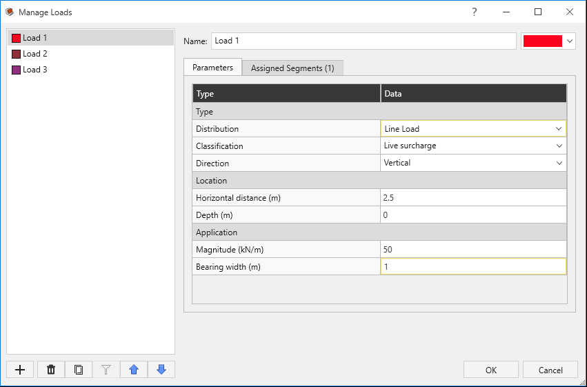
- Select Loading and Support > Loads > Manage Loads

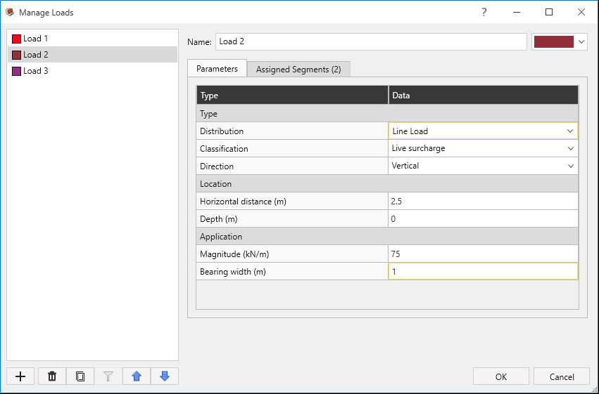
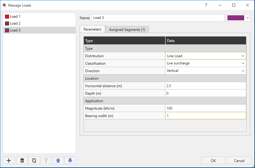
- In the Manage Loads dialog, define 3 Line Loads as follows:
- Click OK to close the dialog.
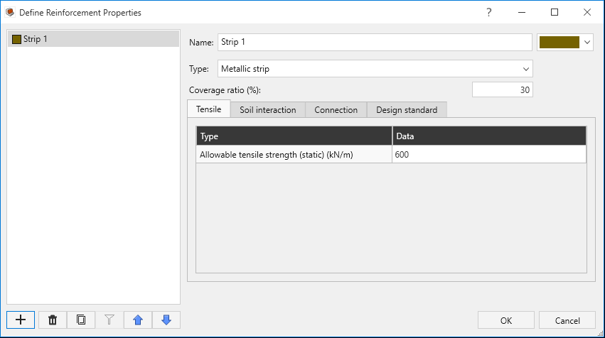
- Select Loading and Support > Reinforcement > Define Properties

- In the Define Reinforcement Properties dialog, define a property with the
values provided in the tables below:
- Tensile tab:
Name/Property Type Allowable tensile strength per strip (static) (kN) Strip width (mm) Strip spacing (m) Strip 1
Metallic strip
30 50 0.2
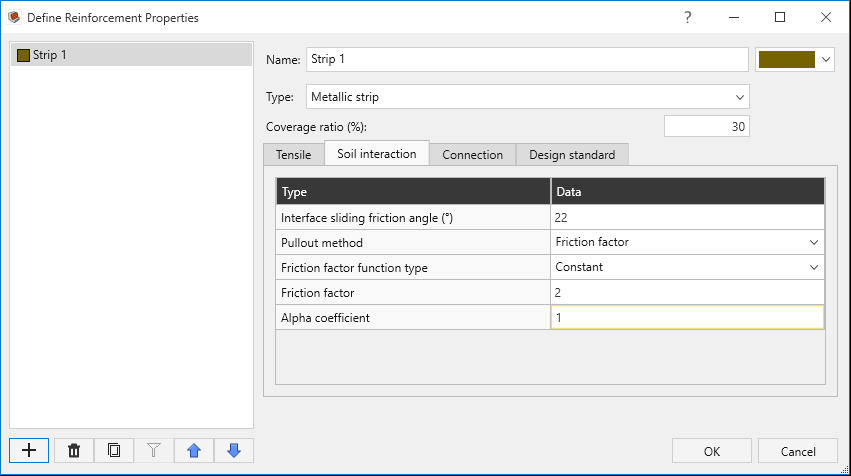
- Soil Interaction tab:
- For the Connection and Design standard tabs, leave the settings as they are. Click OK to close the Define Reinforcement Properties dialog.
- Click on a segment from the Segment Tree, then select Loading and Support >
Reinforcement > Add Layout
 in the toolbar.
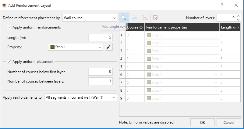
 - In the Add Reinforcement Layout dialog:
- Select the Apply uniform reinforcements checkbox.
- Set Length (m) = 5.
- Then, select the Apply uniform placement checkbox.
- Set Number of courses below first layer = 0 and Number of courses between layers = 1.
- Set the Number of layers = 9.
- Ensure reinforcement layout matches the table below, then click OK.
Name/Load |
Distribution | Horizontal distance (m) | Magnitude (kN/m) | Bearing width | Assigned segments |
|---|---|---|---|---|---|
Load 1 |
Line Load |
2.5 | 50 | 1 | Segment 1 |
Load 2 |
Line Load |
2.5 | 75 | 1 | Segment 2, Segment 3 |
Load 3 |
Line Load |
2.5 |
100 | 1 | Segment 4 |
| Name/Property | Interface sliding friction angle (o) | Pullout method | Friction factor function type | Friction factor |
Alpha coefficient |
|---|---|---|---|---|---|
Strip 1 |
22 |
Friction factor | Constant | 2 | 1 |
| Row | Course | Reinforcement properties | Length (m) |
|---|---|---|---|
1 |
0 |
Strip 1 |
5 |
2 |
1 |
Strip 1 |
5 |
3 |
2 |
Strip 1 |
5 |
4 |
3 |
Strip 1 |
5 |
5 |
4 |
Strip 1 |
5 |
6 |
5 |
Strip 1 |
5 |
7 |
6 |
Strip 1 |
5 |
8 |
7 |
Strip 1 |
5 |
9 |
8 |
Strip 1 |
5 |
7.0 Results
- Go to the Results ribbon.
- Select Results > Compute > Compute to run the analysis.
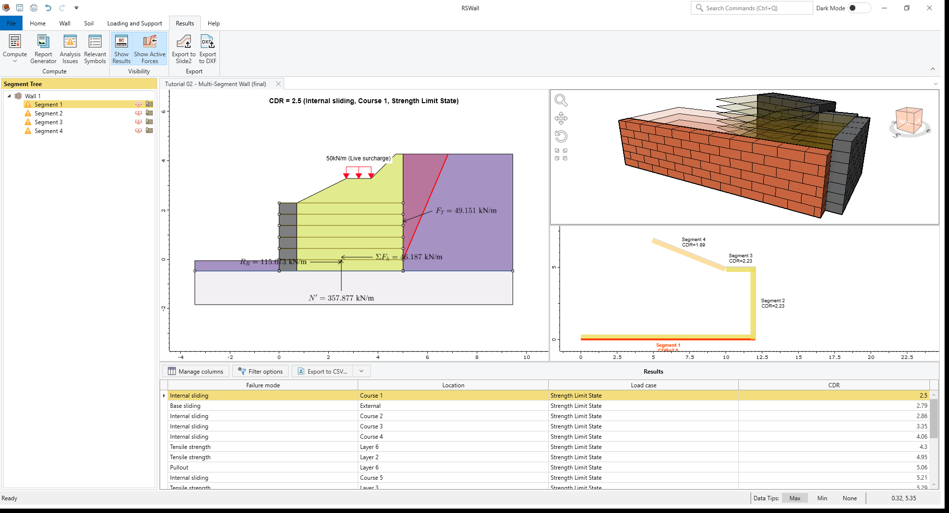
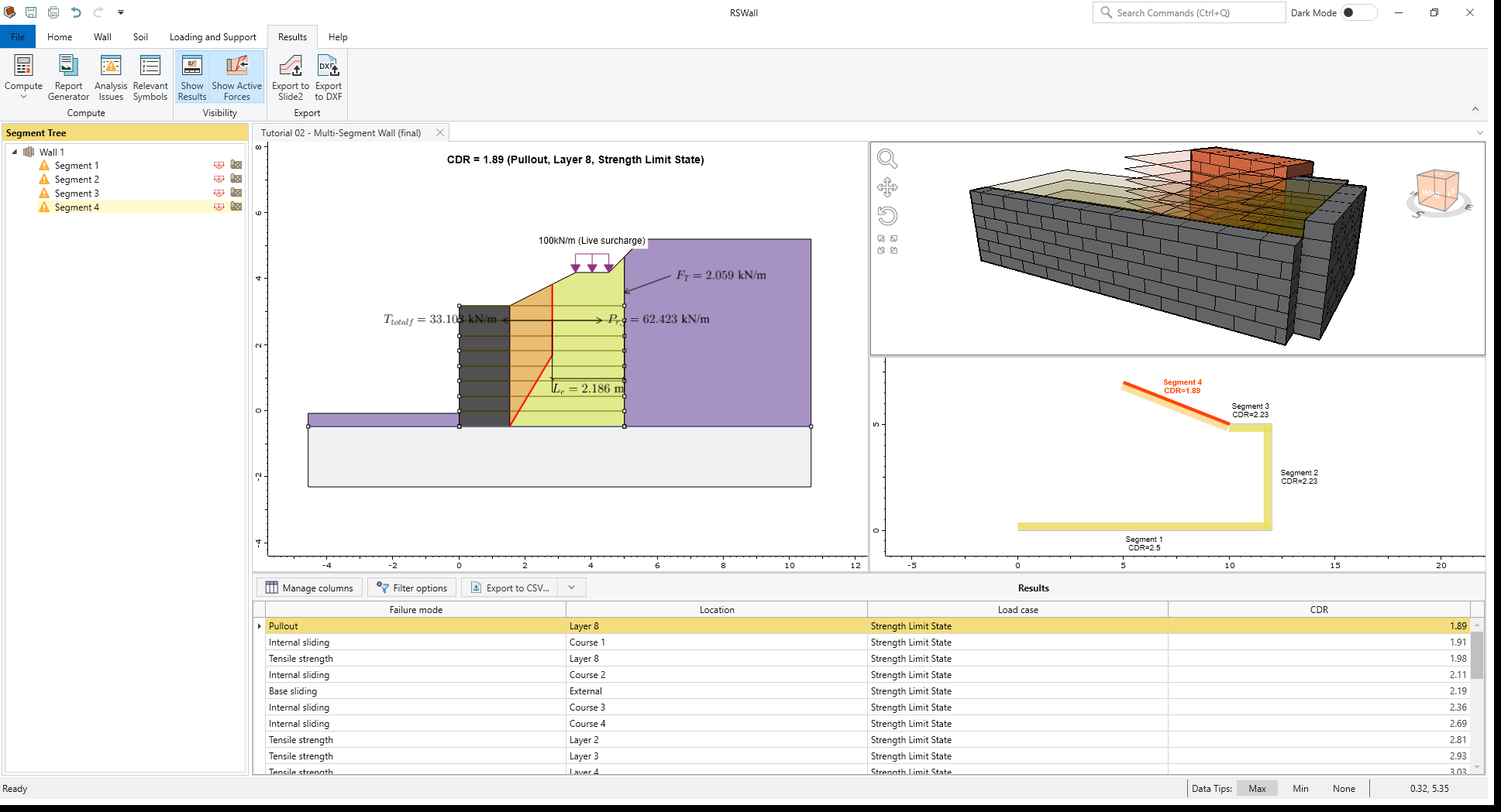
Once computed, the results will resemble the following image for segments 1 and 4:
- In the Segment Tree, there is a warning icon beside all the segments. This means that the
Analysis Issues
dialog should be reviewed. Select Results > Compute > Analysis Issues
 to open the dialog.
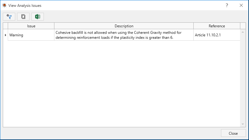
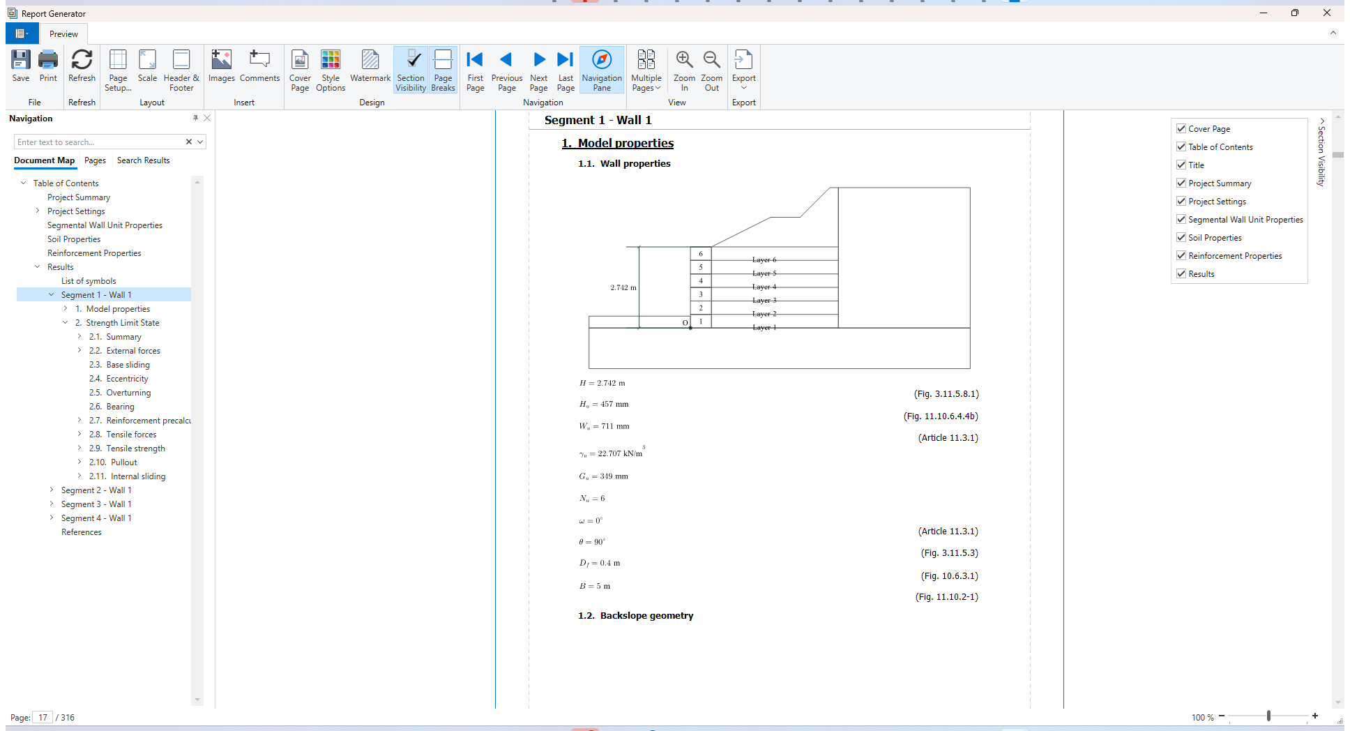
This is just a general warning and does not indicate that anything is wrong with the model. Close the dialog. - Select Results > Compute > Report Generator
 to render a report. The Report Generator in
RSWall provides all the hand calculations for the output results of the RSWall program.
to render a report. The Report Generator in
RSWall provides all the hand calculations for the output results of the RSWall program. - Once the report is ready, click on the Results section under Navigation.
- In the Results section, a List of symbols used in the analysis is provided. For each of the 4
segments modelled in this example, there are detailed hand calculations provided under their respective sections
in the report.
- Close the Report Generator.
8.0 Slide2 Overall Stability Analysis
This section will guide you through exporting the RSWall project to Slide2 and conducting an overall stability analysis.
- Select Results > Export > Export to Slide2

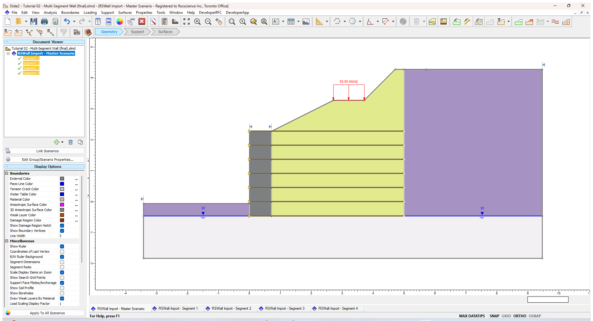
- In the Export to Slide2 dialog, select the All Segments checkbox and click Open in Slide2.
- The model will open in Slide2. After saving the file, you will see a warning regarding connecting water tables from the RSWall model to form a singular water table in Slide2.
- Select File > Save As and save the Slide2 file as Tutorial2 Multi Segment Wall.
- Ensure the model’s slope limits are in the same locations as the image below. To modify the location of a slope
limit, right click on a slope limit and select Move Limits. Then drag the limits to the desired
location on the model.
 RSWall models imported into Slide2 will run with the design standard imported from RSWall.
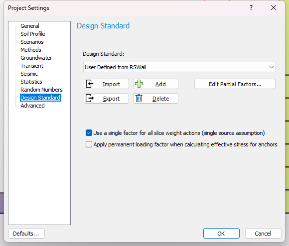
- Select Analysis > Compute
 to compute the model.
 - Select Analysis > Interpret
 . Open all segments in the Interpreter.
The results will display as they are shown below:
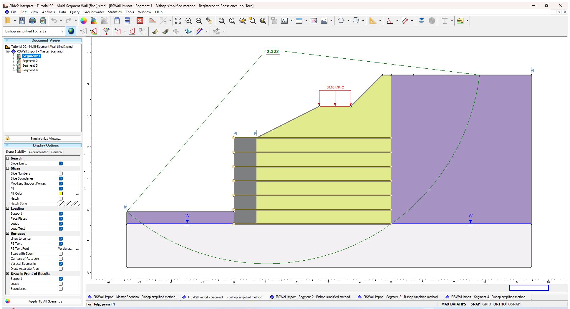
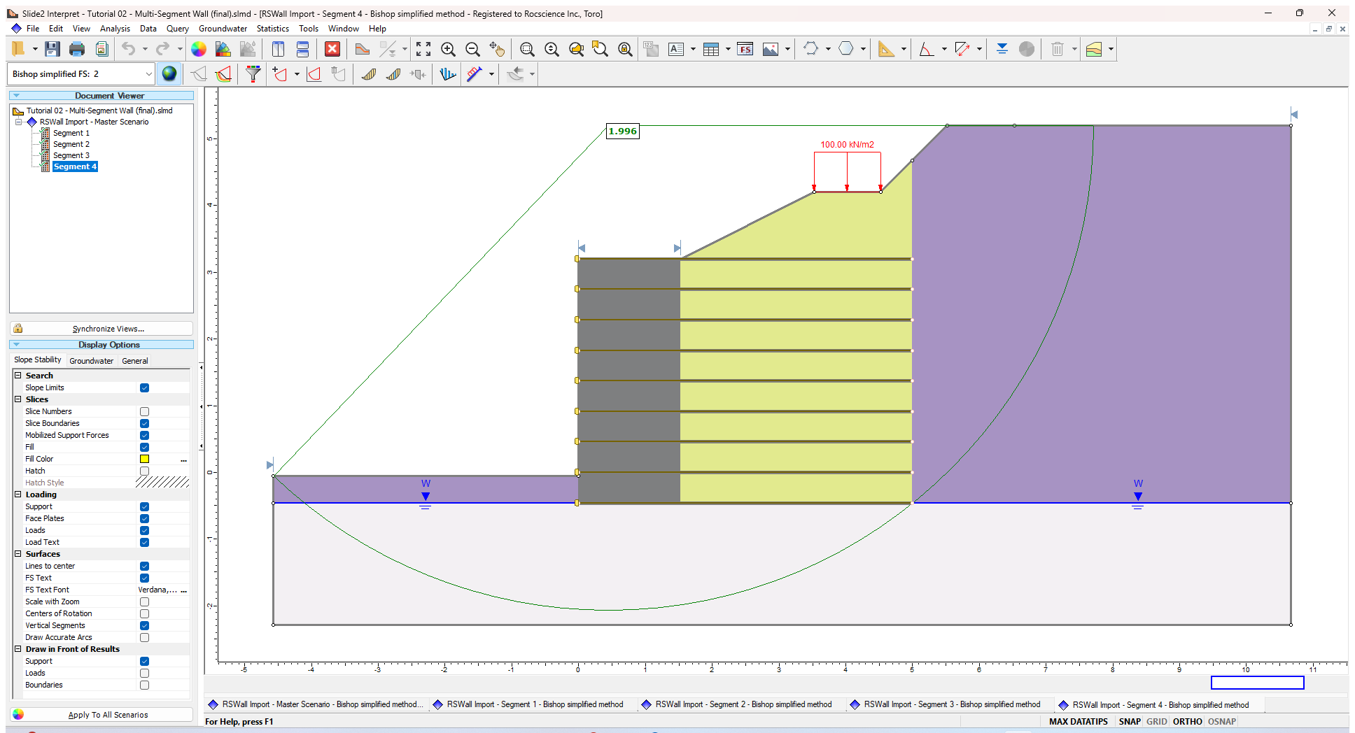
This concludes Tutorial 2.