3 - Gravity Wall
In this tutorial a Gravity wall is designed using the Eurocode 7 (EN 1997:2004) standard. The tutorial guides you step by step through the design process.
Topics Covered:
- Gravity Wall design
- Eurocode 7 Design Standard
- Overall Stability analysis in Slide2
Finished Product:
The finished product of this tutorial can be found in the Tutorial 3 folder. All tutorial files installed with RSWall can be accessed by selecting File > Recent Folders > Tutorials Folder from the RSWall main menu.
1.0 Getting Started
- Open the RSWall program.
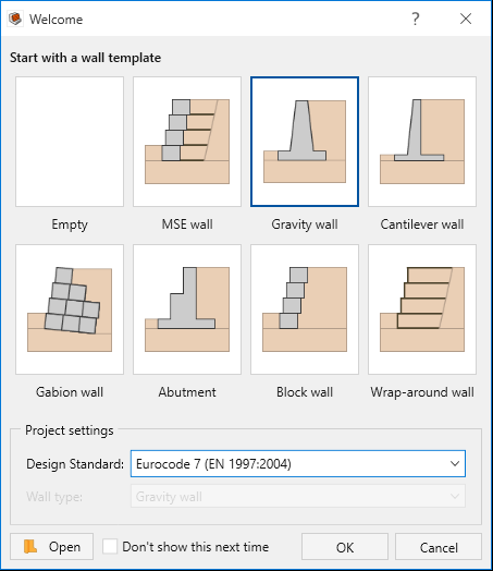
- In the Welcome dialog, select:
- Wall template = Gravity Wall
- Design standard = Eurocode 7 (EN 1997:2004)
- Click OK.
A Gravity wall will be created with the default values of the program. These will be modified later in the tutorial.
2.0 Project Settings
- Go to the Home ribbon and select Home > Project > Project Settings

- Select the Units tab. Change the Units to Imperial, stress as ksf.
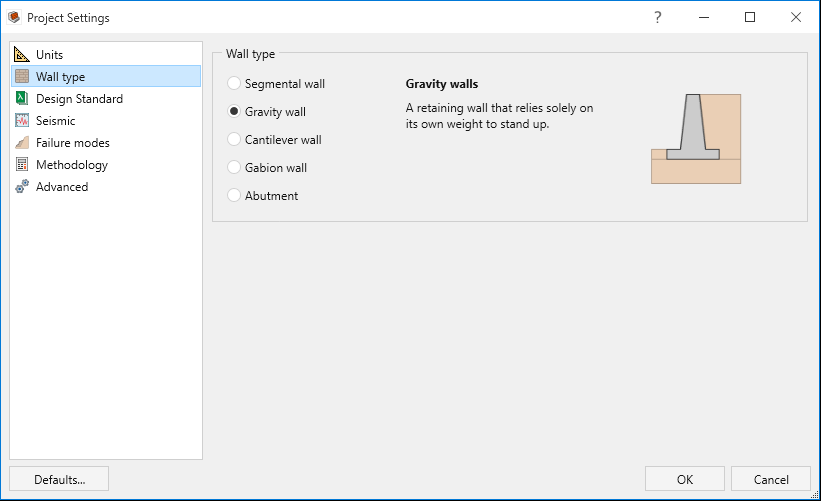
- Select the Wall type tab. Note that Gravity wall is selected. Keep the selection as is.
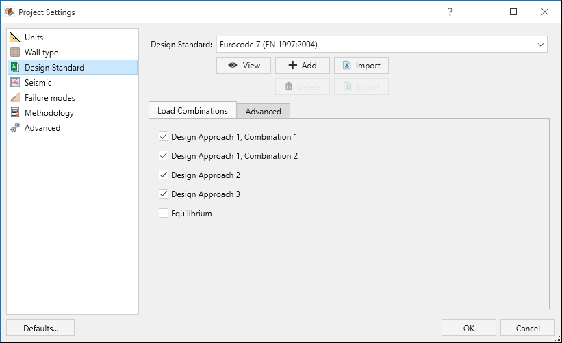
- Select the Design standard tab. Note that Eurocode 7 is selected. Keep the selection as is.
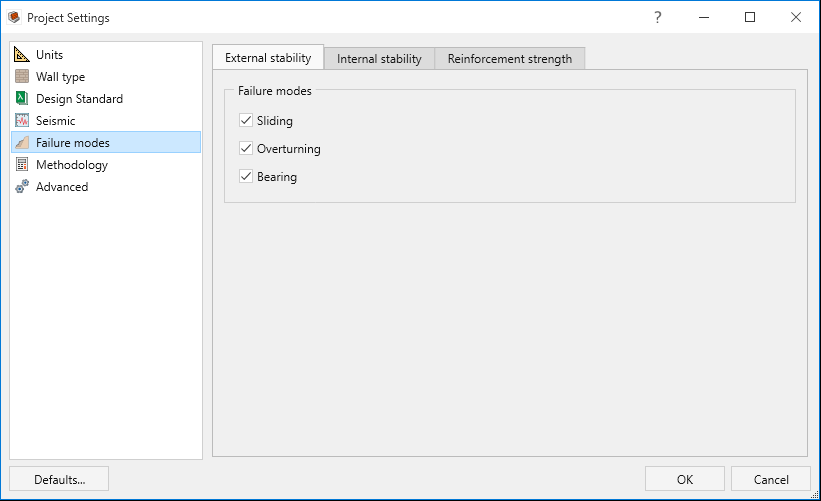
- Select the Failure modes tab. For Gravity walls only External stability is applicable even though Internal stability and Reinforcement strength options are checked. Keep the default selections for External stability.
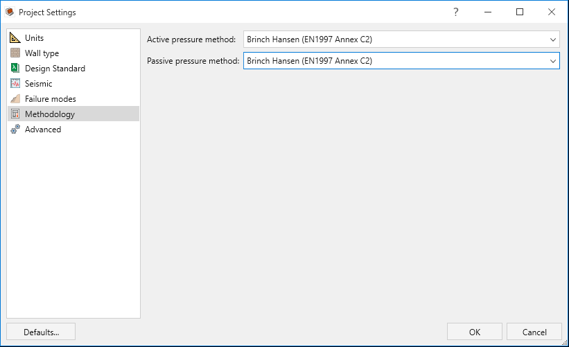
- Select the Methodology tab. Enter:
- Active pressure method = Brinch Hansen (EN1997 Annex C2)
- Passive pressure method = Brinch Hansen (EN1997 Annex C2)
- Click OK to close the dialog.
3.0 Wall
In this part of the design process, we define the wall profile of the model.
- Go to the Wall ribbon.
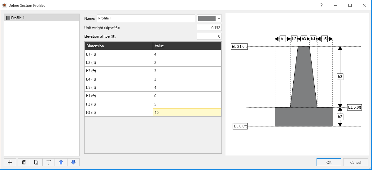
- Select Wall > Wall Profile > Define Section Profile

- Define the dimensions of the Gravity wall as follows:
- Unit weight = 0.152 (kips/f3)
- Elevation at toe = 0 ft
- Click OK to close the dialog.
- Select Wall > Base > Define Base Strength

- For Bearing capacity, User-specified and enter Ultimate bearing capacity = 5 ksf.
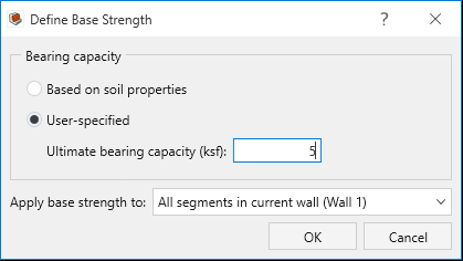
- Click OK to close the dialog.
| Dimension (ft) | Value |
b1 |
4 |
b2 |
2 |
b3 |
3 |
b4 |
2 |
b5 |
4 |
| h1 | 0 |
h2 |
5 |
h3 |
16 |
4.0 Soil
In this part of the design process, we define the soil properties and assign them to different regions.
- Go the Soil ribbon.
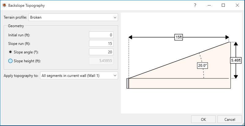
- Select Soil > Soil Geometry > Backslope Topography

- Select Terrain profile = Broken.
- Enter the following Geometry parameters:
- Initial run = 0 ft
- Slope run = 15 ft
- Slope angle = 20 degrees
- Click OK to close the dialog.
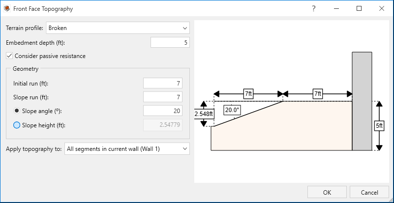
- Select Soil > Soil Geometry > Front Face Topography

- Select Terrain profile = Broken
- Enter Embedment depth = 5 ft
- Tick the check box for Consider passive resistance.
- Enter the following Geometry parameters:
- Initial run = 7 ft
- Slope run = 7 ft
- Slope angle = 20
- Click OK to close the dialog.
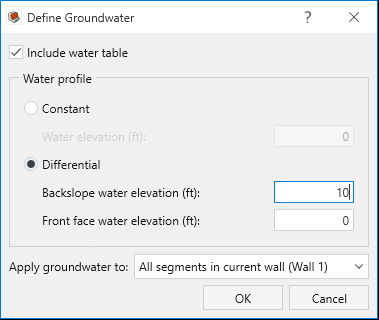
- Select Soil > Groundwater > Define Groundwater

- Tick the checkbox for Include water table.
- For Water Profile select Differential and enter:
- Backslope water elevation = 10ft
- Front face water elevation = 0 ft
- Click OK to close the dialog.
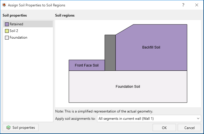
- Select Soil > Soil Conditions > Define Soil Properties

- Define the soil properties as follows:
- Select Soil > Soil Conditions > Assign Soil Properties

- Assign the properties as follows:
- Click OK to close the dialog.
| Soil name\Property | Unit Weight (kips/ft3) | Saturated Unit Weight (kips/ft3) | Friction Angle (o) | Soil-Structure friction Angle (o) | Long-term cohesion (ksf) |
| Retained | 0.127 | 0.132 | 35 | 27 | 0.05 |
| Foundation | 0.13 | 0.14 | 38 | 20 | 0.06 |
5.0 Loading and Support
In this part of the design process, we will define a live load, our reinforcement properties and arrangement.
- Go the Loading and Support ribbon.
- Select Loading and Support > Loads > Manage Loads

- Enter a load of:
- Magnitude = 0.25 ksf
- Horizontal distance = 15 ft
- Magnitude = 0.25 ksf
- Select the Assigned Segments tab and and assign the load Segment 1.
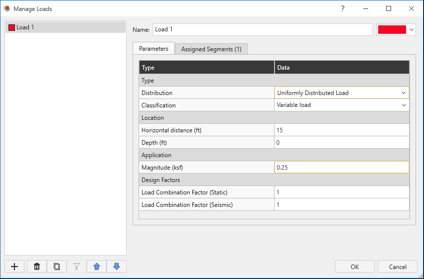
- Click OK to close the dialog.
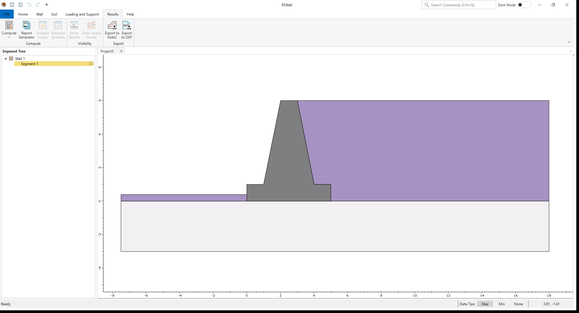
6.0 Results
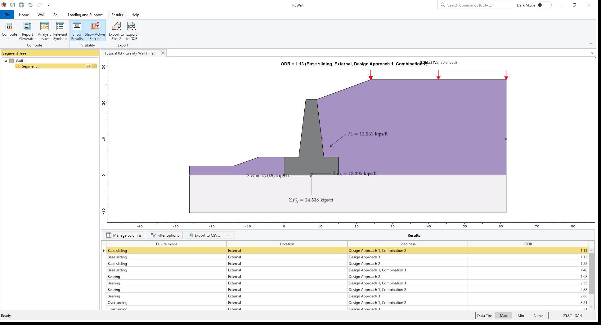
- Select the Result ribbon.
- Select Results > Compute > Compute

The results are shown below. The base Sliding failure mode controls the analysis for Design approach 1, Combination 2.
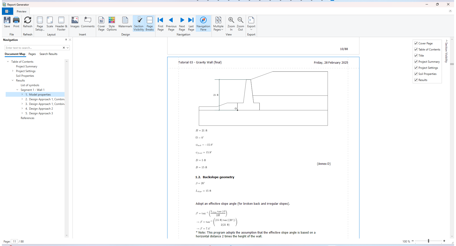
- Select Results > Compute > Report Generator

Report Generator in RSWall provides all the hand calculations for the output results of the RSWall program.
- In the Navigation tree, click on the Results section.
At the beginning of the section, the List of symbols used in the analysis is provided.
For each design approach of Eurocode 7, hand calculations are provided separately.
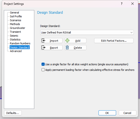
7.0 Slide2 Overall Stability Analysis
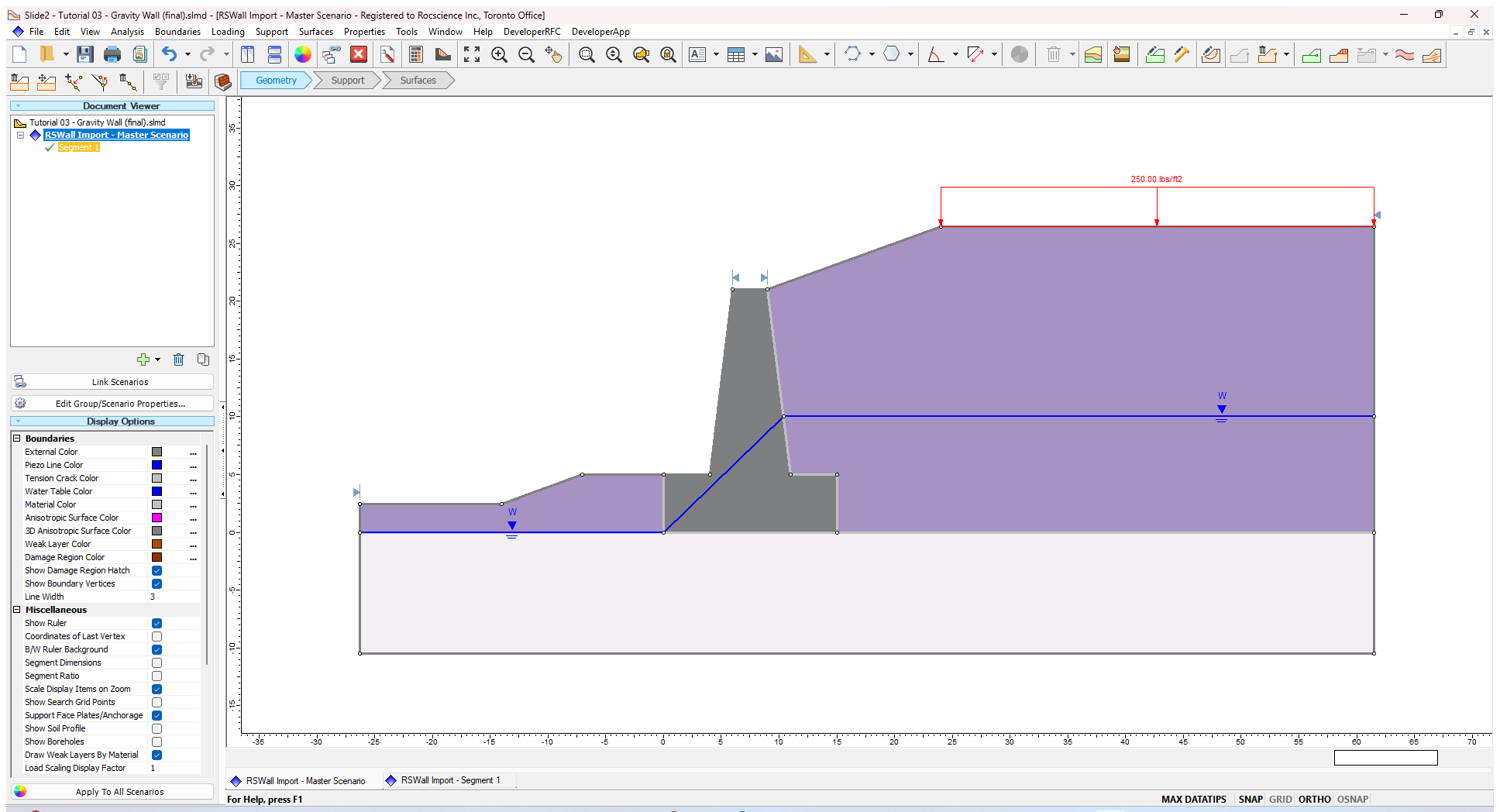
- Select Results > Export > Export to Slide2

- Tick the check box for Segment 1.
- Click Open in Slide2 to launch the Slide2 program.
- Save the Slide2 file as "Tutorial3, Gravity wall."
- Select Analysis > Compute
 to compute the model.
 - Select Analysis > Interpret
 to launch the Interpreter.
The results are shown as below:
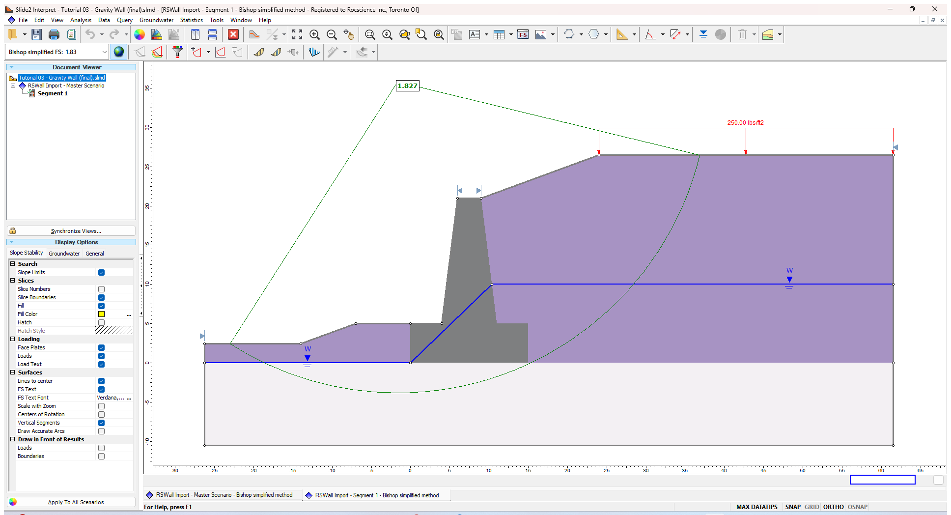
The overall stability is satisfied in this model.