4 - Gabion Wall
In this tutorial a Gabion wall is designed using AASHTO 2020 standard. The tutorial guides step by step through the design process.
Topics Covered:
- Gabion wall design
- AASHTO 2020 design standards
- Overall Stability Analysis in Slide2
Finished Product:
The finished product of this tutorial can be found in the Tutorial 4 folder. All tutorial files installed with RSWall can be accessed by selecting File > Recent Folders > Tutorials Folder from the RSWall main menu.
1.0 Getting Started
- Open the RSWall program.
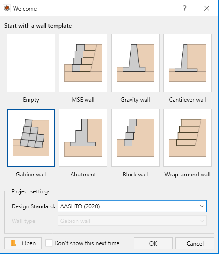
- In the Welcome dialog, select:
- Wall template = Gabion wall
- Design standard = AASHTO 2020
- Wall template = Gabion wall
- Click OK.
A Gabion wall will be created with the default values of the program. These will be modified later in the tutorial.
2.0 Project Settings
- Go to the Home ribbon and select Home > Project > Project Settings

- Select the Units tab. Ensure that Units = Metric, stress as kPa.
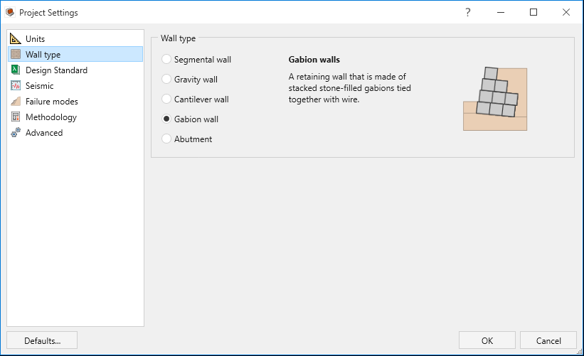
- Select the Wall type tab. Note that Gabion wall is selected. Keep the selection as is.
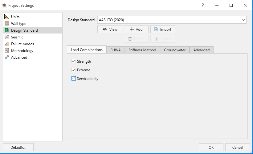
- Select the Design Standard tab. Note that AASHTO (2020) is selected.
- In the Load Combinations tab, tick the check box for Serviceability.
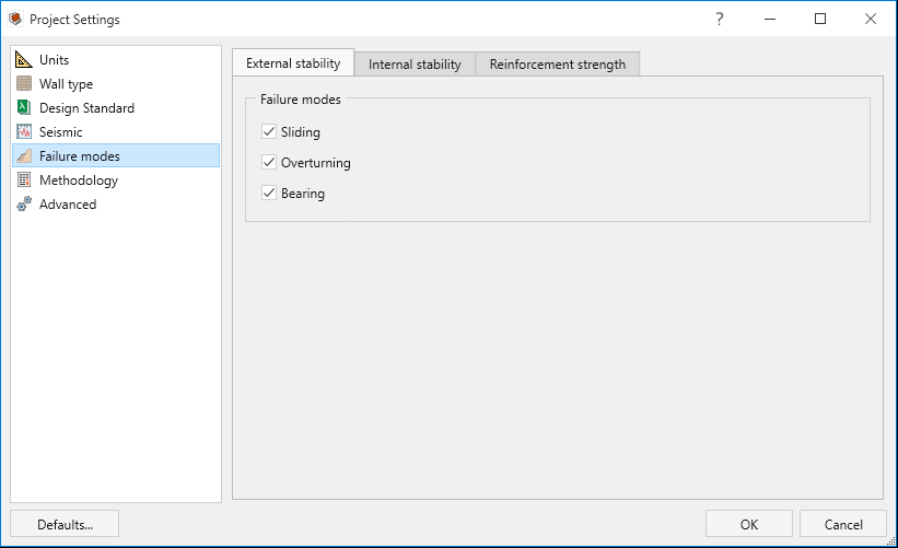
- Select the Failure modes tab. For Gabion walls, only Internal and External stability are applicable even though the Reinforcement strength option is checked. Keep the selections for Internal and External stability as is.
- Select the Methodology tab. Enter Active pressure method = Generalized wedge method.
- Click OK to close the dialog.

3.0 Wall
In this part of the design process, we define the wall profile of the model.
- Go to the Wall ribbon.
- Select Wall > Wall Profile > Define Wall Units

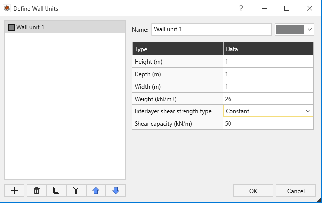
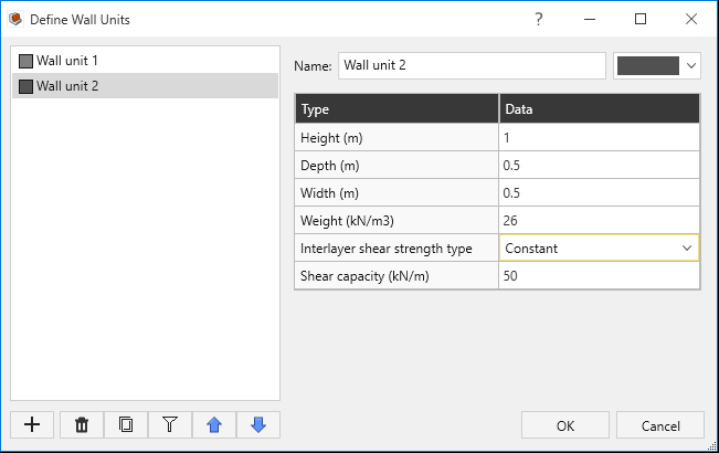
- We will define two wall units. The difference between the wall units is just the width and depth of the gabion baskets.
- Click + Add to add a second Wall Unit.
- Define the two Wall units as shown below:
- Click OK to close the dialog.
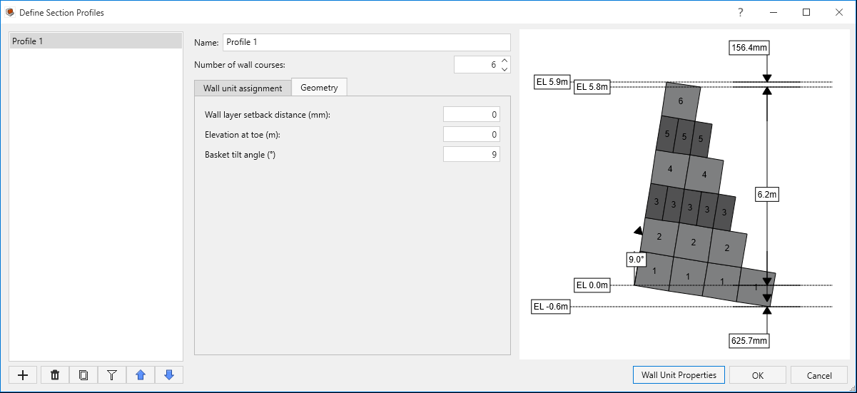
- Select Wall > Wall Profile > Define Section Profile

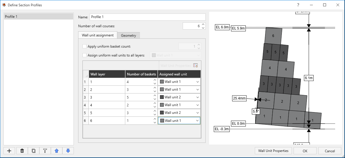
- Define the Number of wall courses as 6.
- In the Wall unit assignment tab, ensure the Wall layer setback distance = 0 mm.
- Define the number of baskets per wall layer and assign their corresponding wall units as follows. (Note: Assign uniform wall units to all layers must be OFF, in order to apply non-uniform wall units for each wall layer)
- In the Geometry tab enter:
- Elevation at toe = 0 m
- Basket tilt angle = 9o
- Elevation at toe = 0 m
- Click OK to close the dialog.
| Wall Unit 1 | Wall Unit 2 | ||
| Type | Data | Type | Data |
| Height (m) | 1 | Height (m) | 1 |
| Depth (m) | 1 | Depth (m) | 0.5 |
| Width (m) | 1 | Width (m) | 0.5 |
| Weight (kN/m3) | 26 | Weight (kN/m3) | 26 |
| Wall layer | Number of Baskets | Assigned wall unit |
| 1 | 4 | Wall unit 1 |
| 2 | 3 | Wall unit 1 |
| 3 | 5 | Wall unit 2 |
| 4 | 2 | Wall unit 1 |
| 5 | 3 | Wall unit 2 |
| 6 | 1 | Wall unit 1 |
4.0 Soil
In this part of the design process, we define the soil properties and assign them to different regions.
- Go to the Soil ribbon.
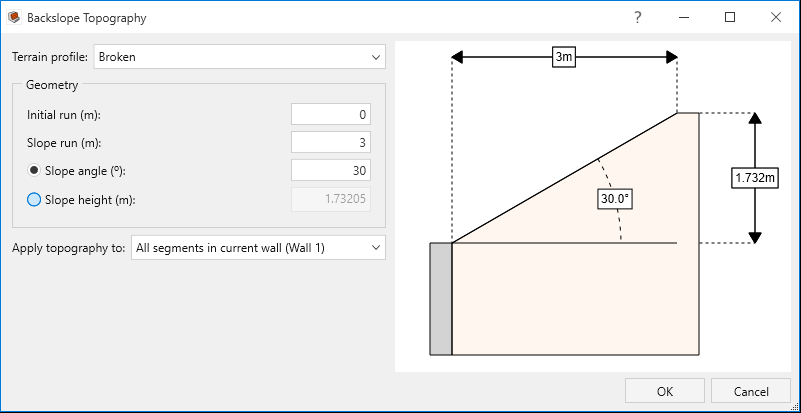
- Select Soil > Soil Geometry > Backslope Topography

- For Terrain profile, select the Broken option and use the following geometry parameters:
- Initial run = 0 m
- Slope run = 3 m
- Slope angle = 30 degrees
- Click OK to close the dialog.
- Select Soil > Soil Geometry > Front Face Topography

- For Terrain profile, ensure Infinite is selected. Enter Embedment depth = 1 m.
- Click OK to close the dialog.
- Select Soil > Soil Conditions > Define Soil Properties

- Define the soil properties as shown below:
- Click OK to close the dialog.
- Select Soil > Soil Conditions > Assign Soil Properties

- Assign the properties as follows:
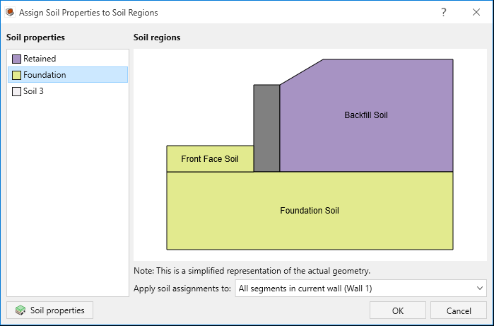
- Click OK to close the dialog.
| Soil name\Property | Unit Weight (kN/m3) | Friction Angle (o) | Soil-Structure friction Angle (o) | Long-term cohesion (kPa) |
| Retained | 21 | 32 | 24 | 0 |
| Foundation | 20 | 30 | 20 | 0 |
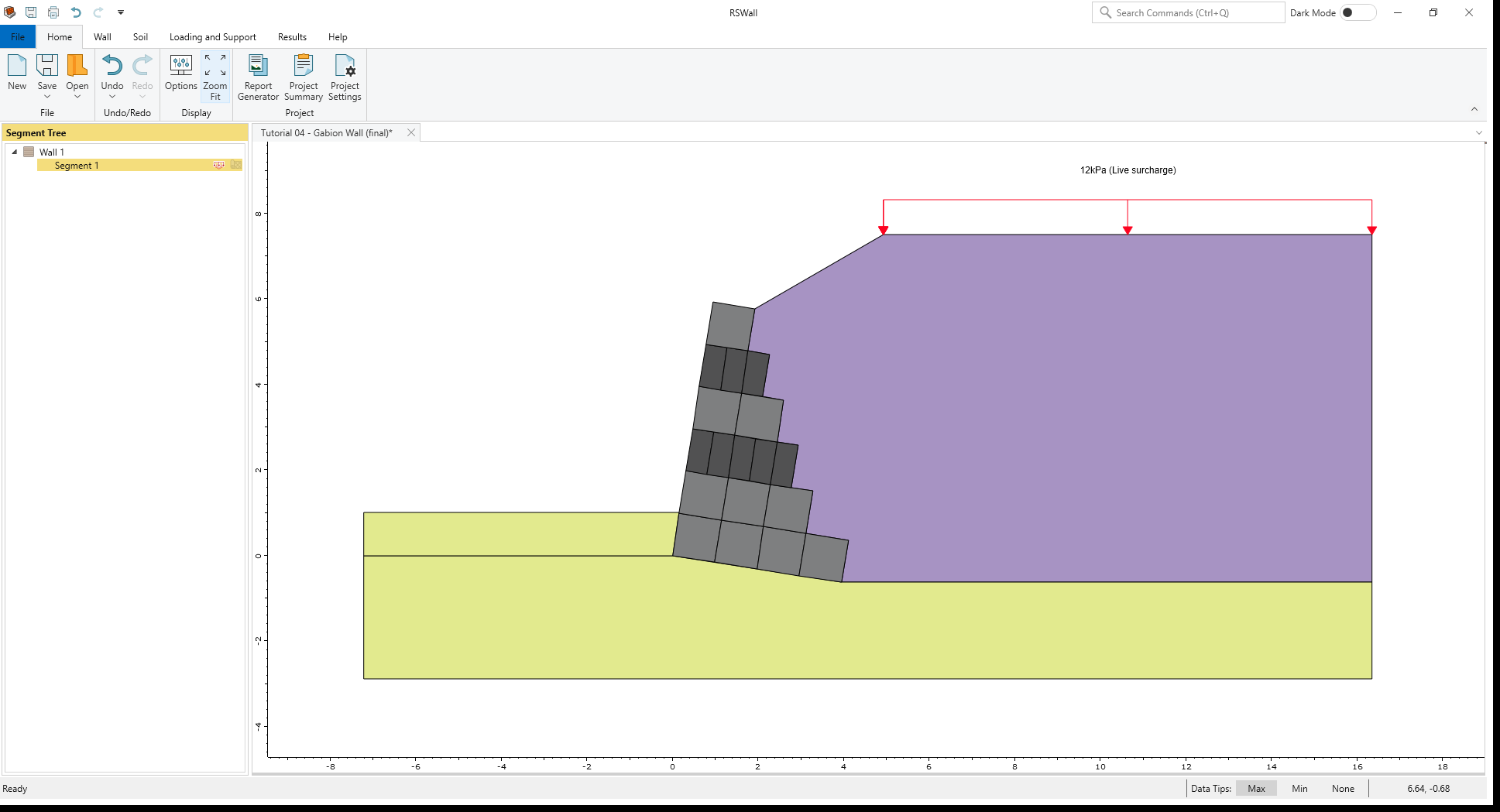
5.0 Loading and Support
In this part of the design process we will define a live load, our reinforcement properties and arrangement.
- Go the Loading and Support ribbon.
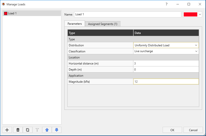
- Select Loading and Support > Loads > Manage Loads

- We will define a 12 kPa load at the distance of 3 m. To do so, enter the following:
- Distribution = Uniformly Distributed Load
- Classification = Live surcharge
- Horizontal distance = 3 m
- Depth = 0 m
- Magnitude = 12 kPa
- Select the Assigned Segments tab and assign the load to Segment 1.
- Click OK to close the dialog.
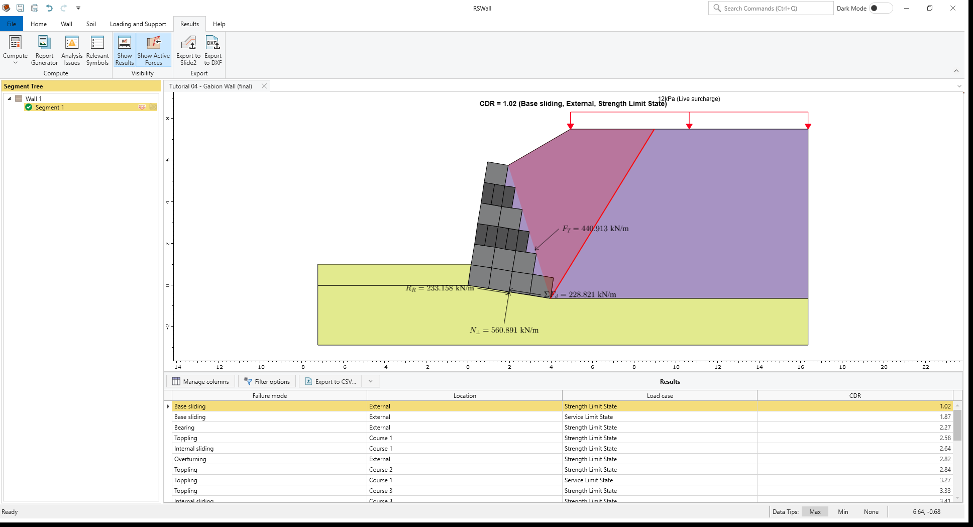
6.0 Results
- Go to the Results ribbon.
- Select Results > Compute > Compute

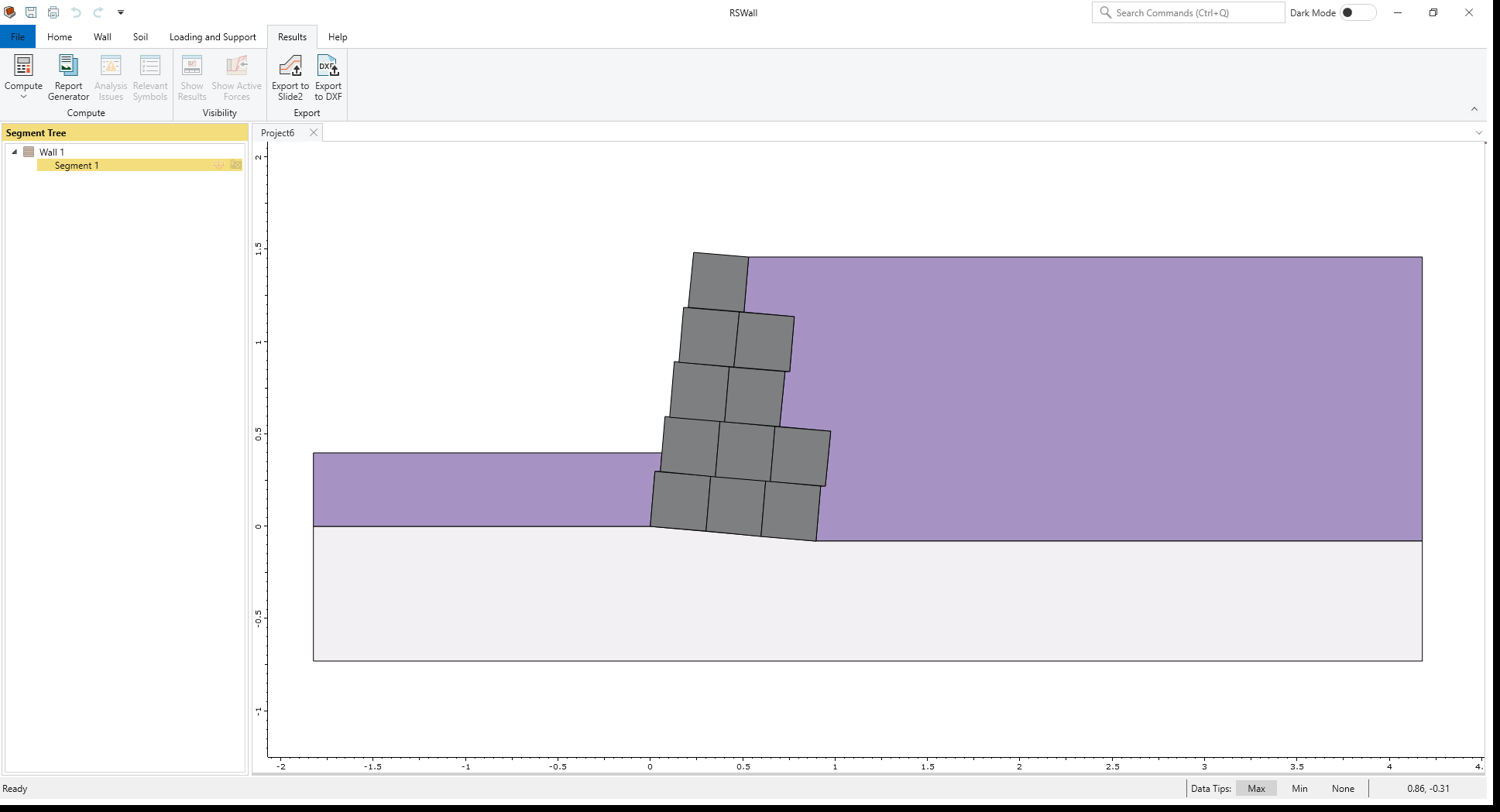
The results are shown below. The base Sliding failure mode controls the analysis for Design approach 1, Combination 2.
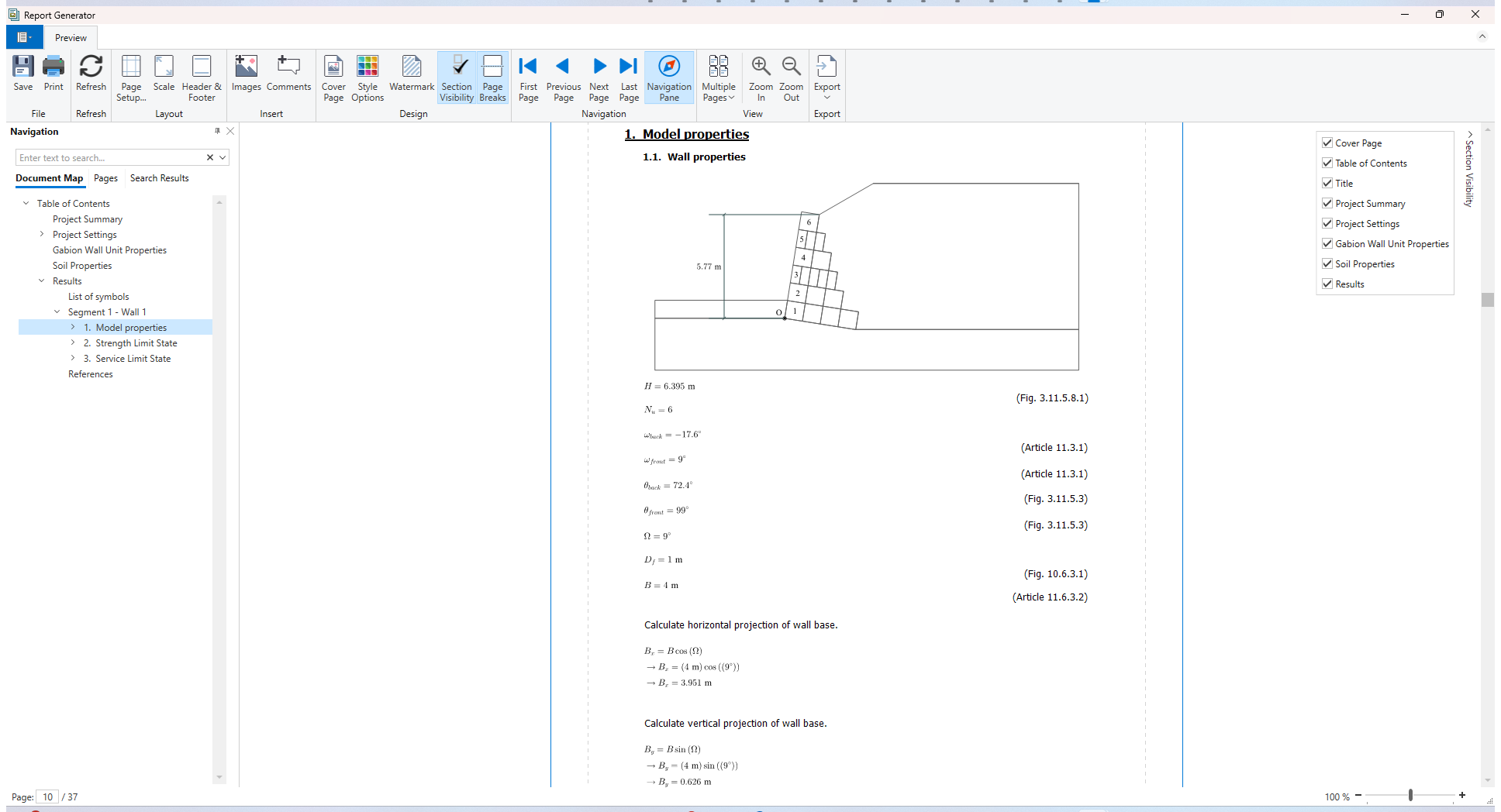
- Select Results > Compute > Report Generator

The Report Generator in RSWall provides all the hand calculations for the output results of the program.
- In the Navigation tree, click on the Results section.
At the beginning of the section, the List of symbols used in the analysis is provided.
For each design approach of Eurocode 7, hand calculations are provided separately.
7.0 Slide2 Overall Stability Analysis
- Open the Slide2 program.
- Select File > Open
 , and open the Slide2 file named Tutorial 04 - Gabion Wall (initial).slmd (in the Tutorial 4 folder).
 - Select Analysis > Compute
 to compute the model.
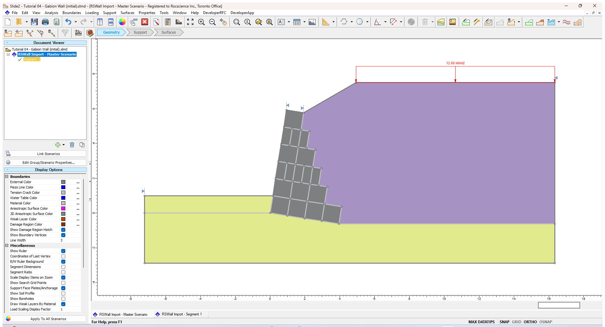
- Select Analysis > Interpret
 to open the Interpreter.
 - The results are shown as below:
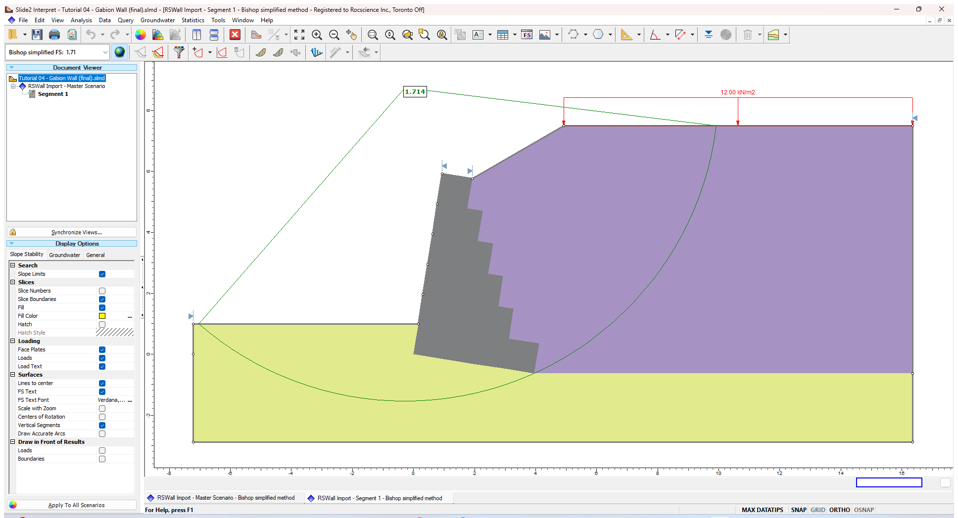
The overall stability is satisfied in this model.
8.0 Additional Exercise
The cohesion method described by Javankhoshdel et al. (2022) can be used to estimate the strength of the gabion units. In this case, we can assume the minimum gabion dimension is 0.5 m per the wall block unit and a tensile strength of 40 kN/m for the tensile strength of the mesh. For the wall block units, the equivalent gabion wall cohesion Cr can be calculated using the below equations:
| 1. | 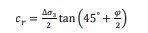 |
| 2. |  |
| 3. |  |
Where φ is the friction angle of the filling material in the baskets, and Δσ3 is the increased confining pressure, which can be determined using Eq. 2 (Bathurst & Karpurapu 1993). In Eq. 2 ft is the tensile strength of the mesh in units of force per unit length, d is the lowest gabion dimension, εa is the axial strain at failure assumed to be 0.05 to 0.07 (Bathurst & Karparapu 1993), and εc is the circumferential strain determined, using Eq. 3.
- Right click on the Segment 1 group and duplicate the group. Rename the new group to Equivalent Cohesion method.
- Select Properties > Define Materials

- Select the Wall block material and change the Cohesion to 115 kPa. Click OK to close the dialog.
- Select Analysis > Compute to compute the model.
When we open the Interpreter, we see the governing surface does not pass through the gabion wall, but under the wall, similar to the failure shown in RSWall.
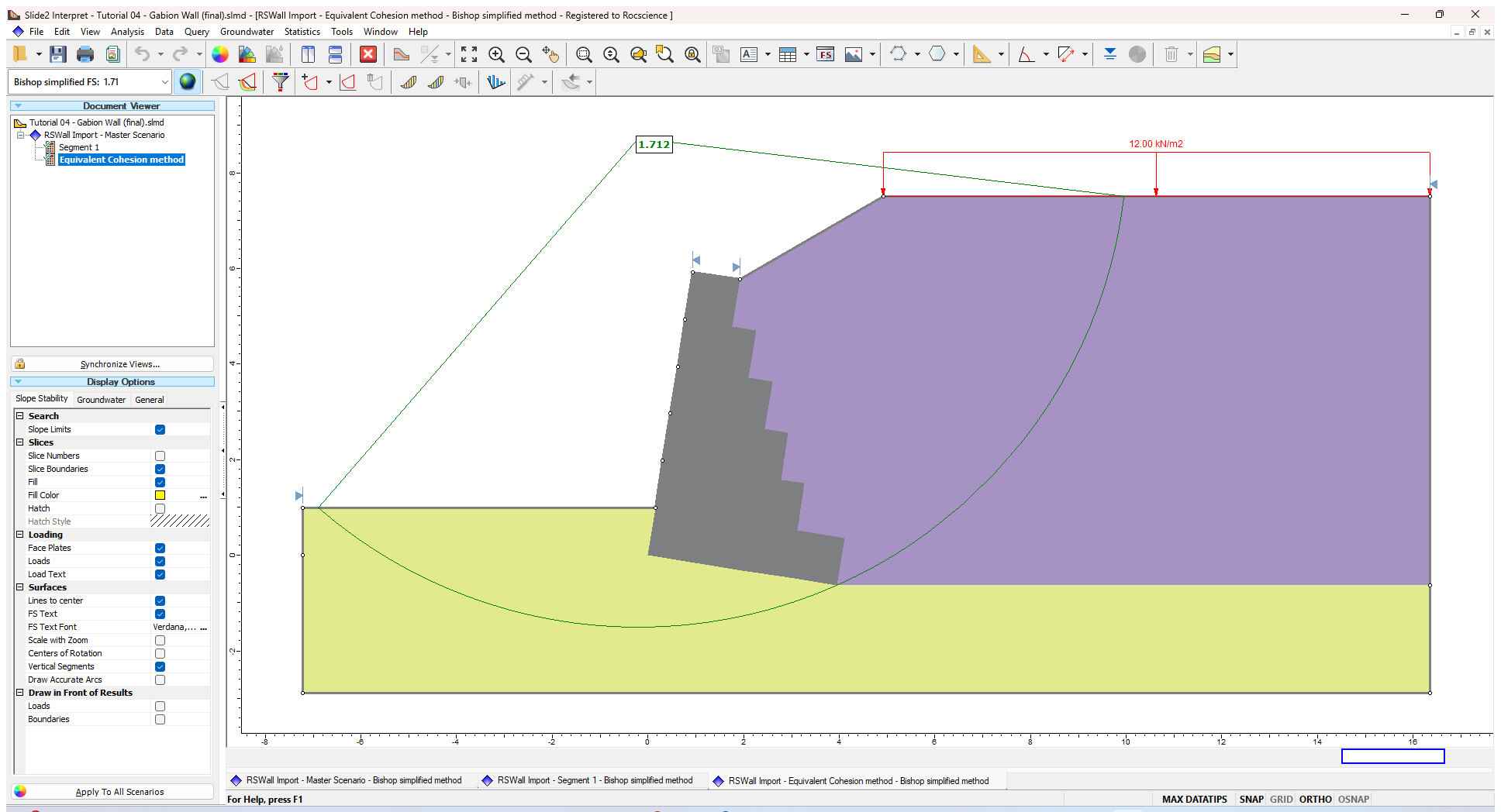
This is more evident using a non-circular analysis as well.
- Return to the Modeler

- Right click on the Equivalent Cohesion method group and duplicate the group. Rename the new group to Equivalent Cohesion method-NC.
- Select Surfaces > Surface Options
 . Change the method to non-circular cuckoo search.
 - Select Analysis > Project settings
 . In the Methods tab, tick the check box for Spencer method. Click OK to close the dialog.
 - Select Analysis > Compute to compute the model.
Additionally, we can introduce weak layers and/or sliding along geosynthetics to evaluate the potential failure through the gabion block interfaces.
- Using the weak layer design suggestions in Javankhoshdel et al. (2022), the cohesion can be estimated as:
- C = ft / b = 40 / 0.5 = 80 kPa where b is the minimum gabion dimension
- Phi = 0.9 * gabion phi = 0.9*45 = 41.5
- Return to the Modeler
- Right click on the Equivalent Cohesion method-NC group and duplicate the group. Rename the new group to Equiv cohesion+WL.
- Select Boundaries > Add Weak Layer
 and add weak layers for the boundaries between the baskets. Assign the Gabion interface weak layer to them.
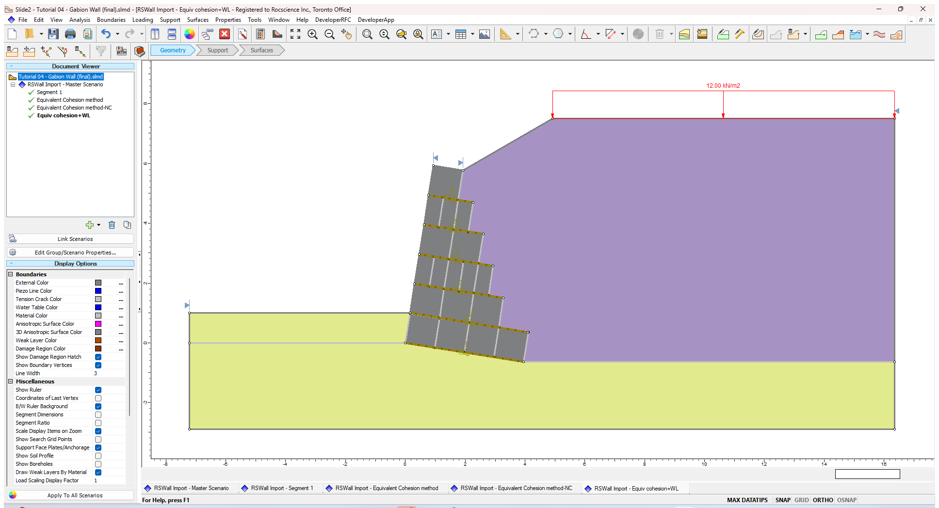
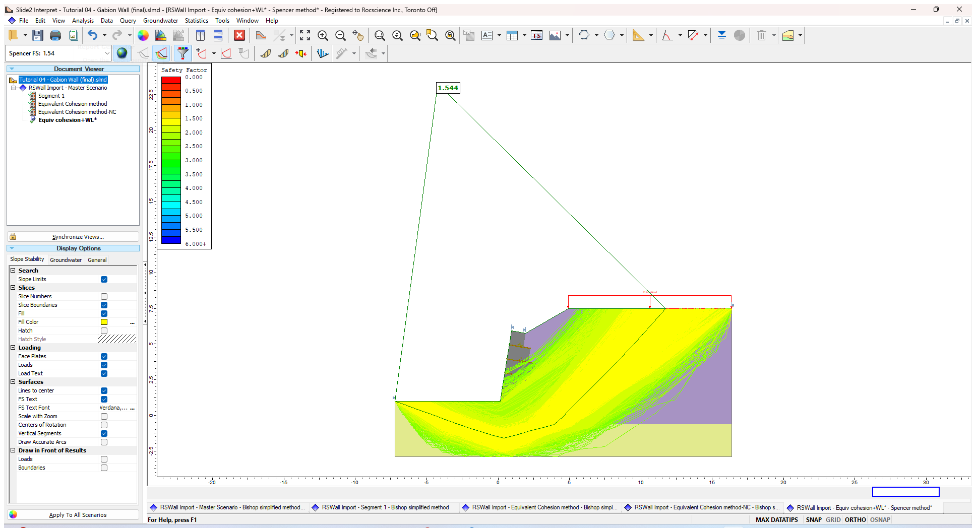
- Select Analysis > Compute to the model. Select Analysis > Interpret to open the Interpreter.
- In the Interpreter, select Data > All surfaces
 . Then select Data > Filter surfaces
  and show Surfaces with a factor of safety below 2.5.
After viewing all available surfaces below FS = 2.5, we can see that although some surfaces go through the gabions via the weak layers, none of them are governing compared to the overall failure under the wall.
The results of this analysis are heavily based on the assumption of the mesh strength and may differ depending on the materials used.
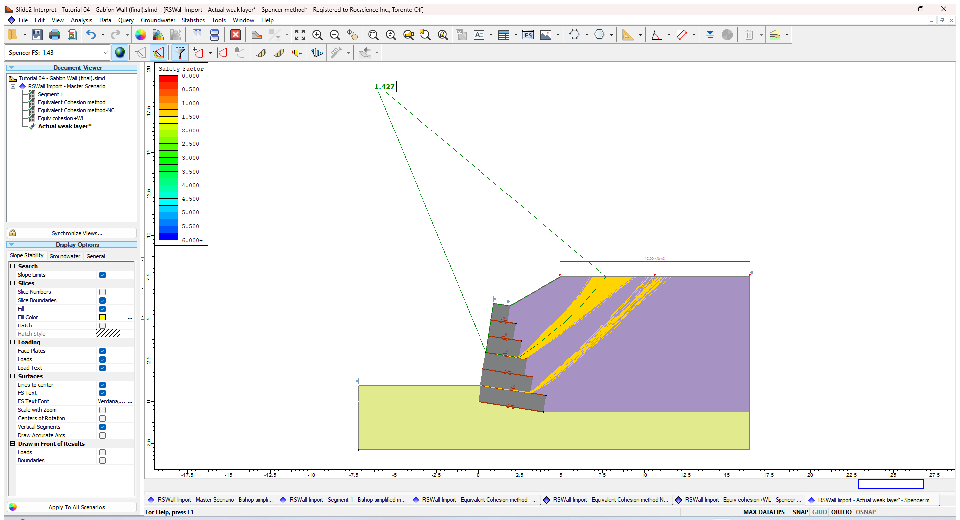
An additional step would be to drastically reduce the properties. For example, setting the cohesion to 5 and phi to 20 results in a new failure through the gabion interface weak layer.
- Return to the Modeler
- Right click on the Equivalent Cohesion method-NC group and duplicate the group. Rename the new group to Actual weak layer.
- Right click on each weak layer and change the material to Weak layer.
- Select Analysis > Compute to compute the model. In the Interpreter , see that we now have a failure through gabion walls due to the weak layer (filter the surfaces for FS< 1.5). Note that this is to demonstrate a possible internal failure depending on the strength between the gabion blocks.
References
Bathurst, R.J. and Karpurapu, R. 1993. Large-Scale Triaxial Testing of Geocell-Reinforced Granular Soils. Geotechnical Testing Journal, 296-303.
Javankhoshdel, S., Sy, L.J., Ma, T., Cami, B., Yacoub, T. Limit equilibrium analysis of gabion walls. GeoCalgary 2022. Geoengineer (2022).