5 - Abutment
In this tutorial an Abutment is designed using a user-defined (based on AASHTO 2020) standard. The tutorial guides you step by step through the design process.
Topics Covered:
- Abutment design
- User defined design standards
- Overall Stability analysis in Slide2
Finished Product:
The finished product of this tutorial can be found in the Tutorial 5 folder. All tutorial files installed with RSWall can be accessed by selecting File > Recent Folders > Tutorials Folder from the RSWall main menu.
1.0 Getting Started
- Open the RSWall program.
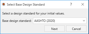
- In the Welcome dialog, select:
- Wall template = Abutment
- Design standard = AASHTO 2020
- Click OK.
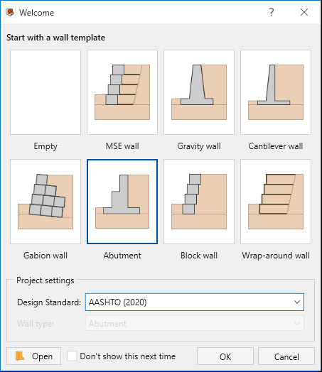
An Abutment will be created with the default values of the program. These will be modified later in the tutorial.
2.0 Project Settings
- Go to the Home ribbon and select Home > Project > Project Settings

- Select the Units tab. Change the Units to Imperial, stress as psf.
- Select the Wall type tab. Note that Abutment is selected. Keep the selection as is.
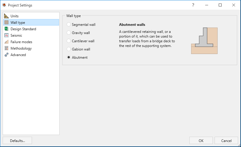
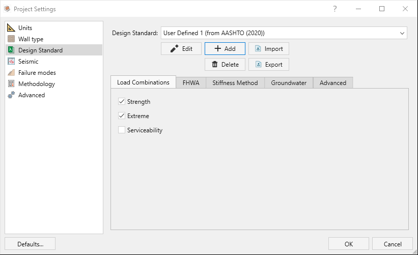
- Select the Design Standard tab.
- Note that AASHTO (2020) is selected. Click + Add to add a User Defined Design Standard. Keep the selection of AASHTO 2020 as the Base design standard and click Next.
- In the Load and Resistance factors table, change all the values to 1.

- Click OK. The user-defined standard is created which will follow AASHTO recommendations.
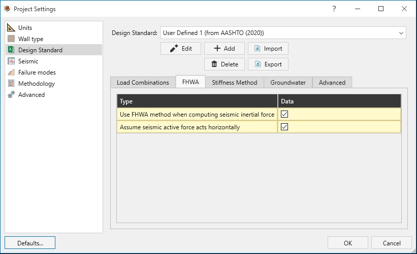
- Select the FHWA tab (still inside the Design Standard tab). Tick the check boxes for both Use FHWA method when computing seismic inertial force and Assume seismic active forces acts horizontally
- Note that AASHTO (2020) is selected. Click + Add to add a User Defined Design Standard. Keep the selection of AASHTO 2020 as the Base design standard and click Next.
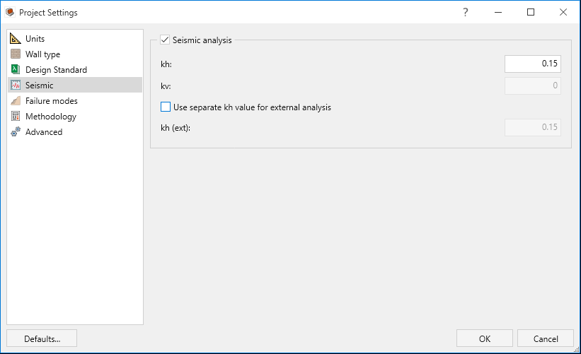
- Select the Seismic tab. Tick the checkbox to turn on the Seismic analysis option. Define a value of kh = 0.15 for the horizontal seismic coefficient.
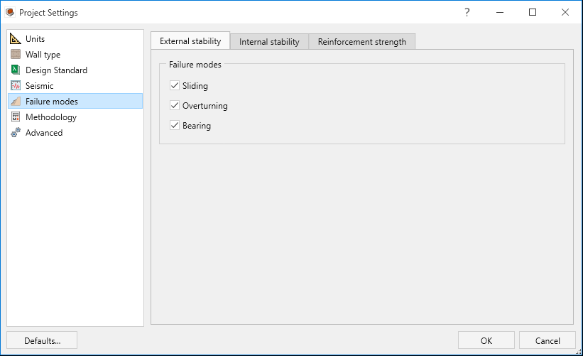
- Select the Failure modes tab. For Abutments only External stability is applicable even though Internal Stability and Reinforcement strength options are checked. Keep the selections as is for External stability.
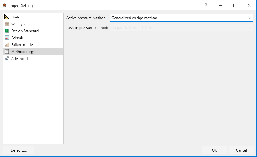
- Select the Methodology tab. For the Active pressure method select Generalized wedge method.
- Click OK to save your selections and close the Project Settings.
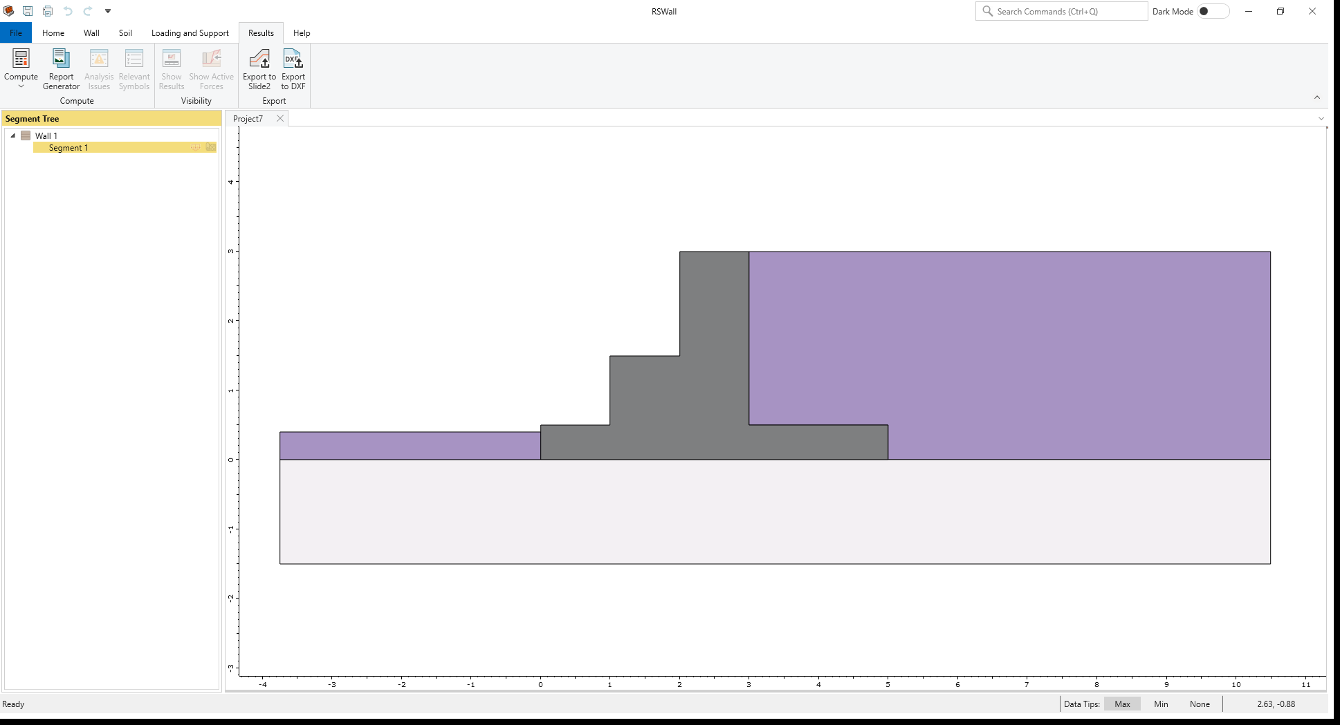
3.0 Wall
In this part of the design process, we define the wall profile of the model.
- Go to the Wall ribbon.
- Select Wall > Wall Profile > Define Section Profile

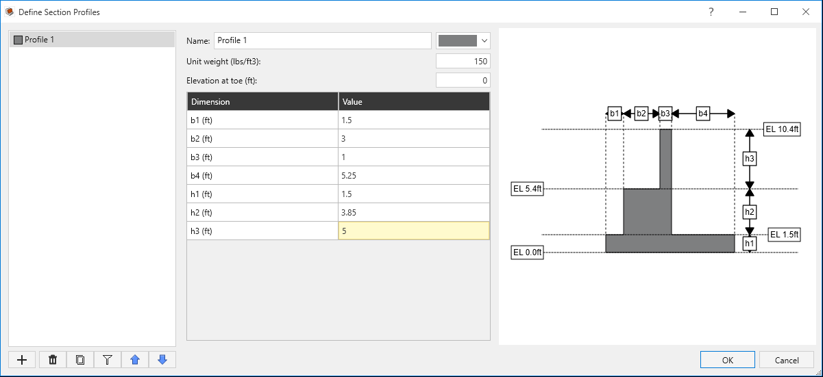
- Define the dimensions of the Abutment as follows:
- Unit weight = 150 lbs/f3
- Elevation at toe = 0 ft
- Click OK to close the dialog.
- Select Wall > Base > Define Base Strength

- For Bearing capacity select User-Specified
and enter Ultimate bear capacity = 12757 psf
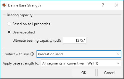
- Click OK to close the dialog.
| Dimension (ft) | Value |
b1 |
1.5 |
b2 |
3 |
b3 |
1 |
b4 |
5.25 |
h1 |
1.5 |
h2 |
3.85 |
h3 |
5 |
4.0 Soil
In this part of the design process, we define the soil properties and assign them to different regions.
- Go the Soil ribbon.
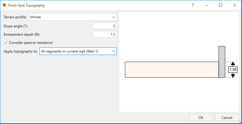
- Select Soil > Soil Geometry > Front Face topography

- Enter Embedment depth = 1.5 ft. Tick the check box for Consider passive resistance and click OK.
- Select Soil > Soil Conditions > Define Soil Properties

- Define the soil properties as shown below:
- Click OK to close the dialog.
- Select Soil > Soil Conditions > Assign Soil Properties

- Assign the properties as follows:
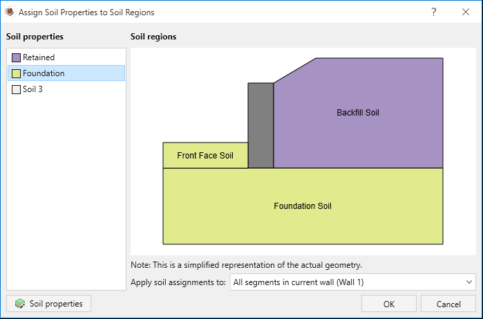
- Click OK to close the dialog.
| Soil Name\Property | Unit weight (lbs/ft3) | Friction angle (o) | Soil-structure friction angle (o) | Long-term cohesion (psf) |
| Retained | 125 | 32 | 24 | 0 |
| Foundation | 125 | 34 | 26 | 0 |
5.0 Loading and Support
In this part of the design process, we will define different load types.
- Go to the Loading and Support ribbon.
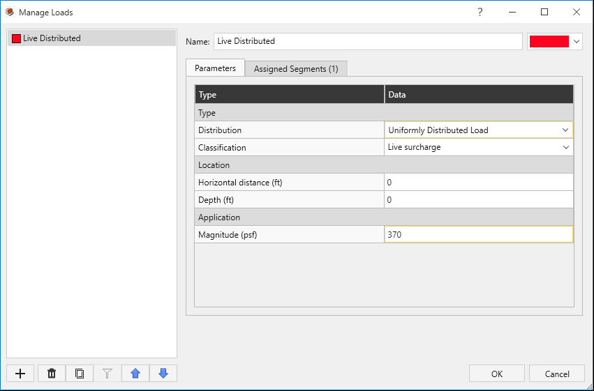
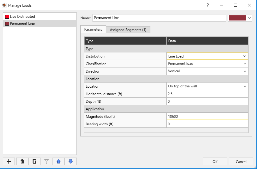
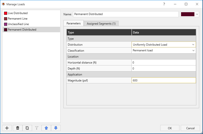
- Select Loading and Support > Loads > Manage Loads

- Click the + Add button 3 times to add 3 additional loads (for a total of 4 load types.)
- Enter the following loads:
- Assign each load to Segment 1.
- Click OK to close the dialog.
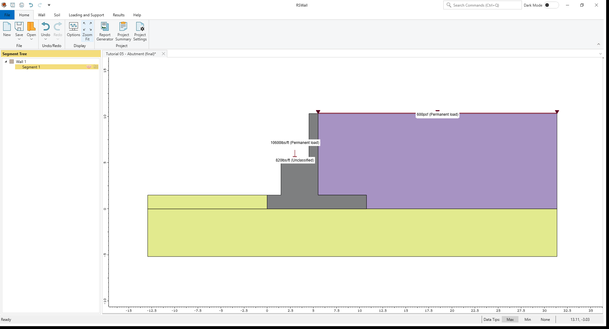
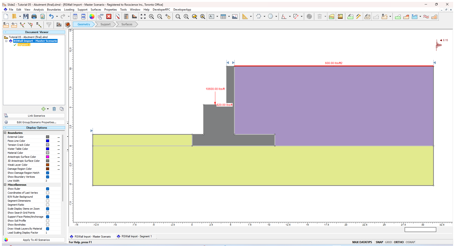
| Name | Distribution | Classification | Direction | Horizontal Distance (ft) | Magnitude | Bearing Width (ft) | Location |
| Live distributed | Uniformly distributed | Live surcharge | - | 0 | 370 psf | - | - |
| Permanent Line | Line Load | Permanent load | Vertical | 2.5 | 10600 lbs/ft | 0 | On top of the wall |
| Unclassified Line | Line Load | Unclassified | Horizontal | 2.5 | 820 lbs/ft | 0 | On top of the wall |
| Permanent Distributed | Uniformly distributed | Permanent load | - | 0 | 600 psf | - | - |

6.0 Results
- Go to the Results ribbon.
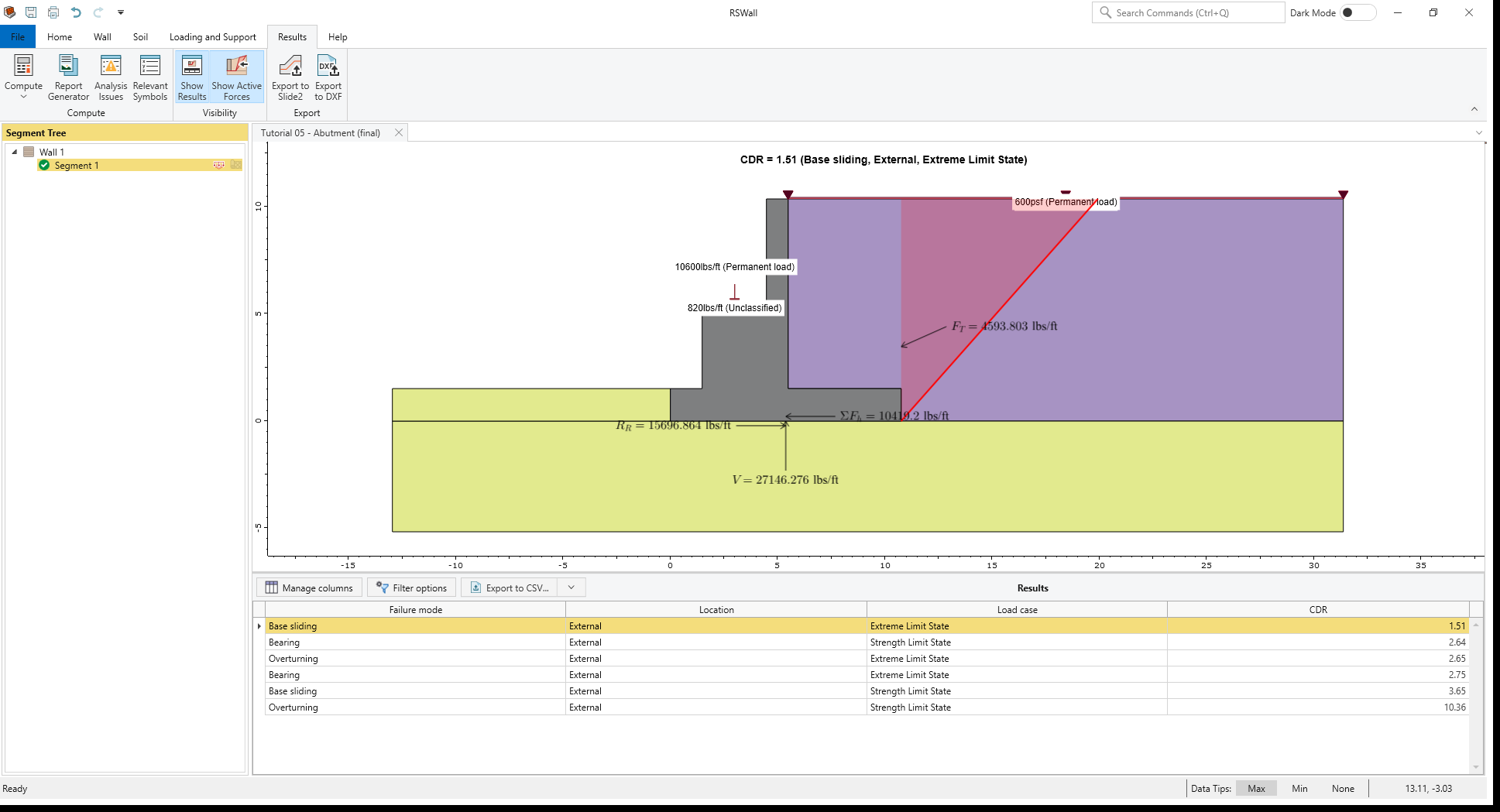
- Select Results > Compute > Compute

The results are shown below. The base Sliding failure mode for the Extreme Limit State is the governing failure mode.
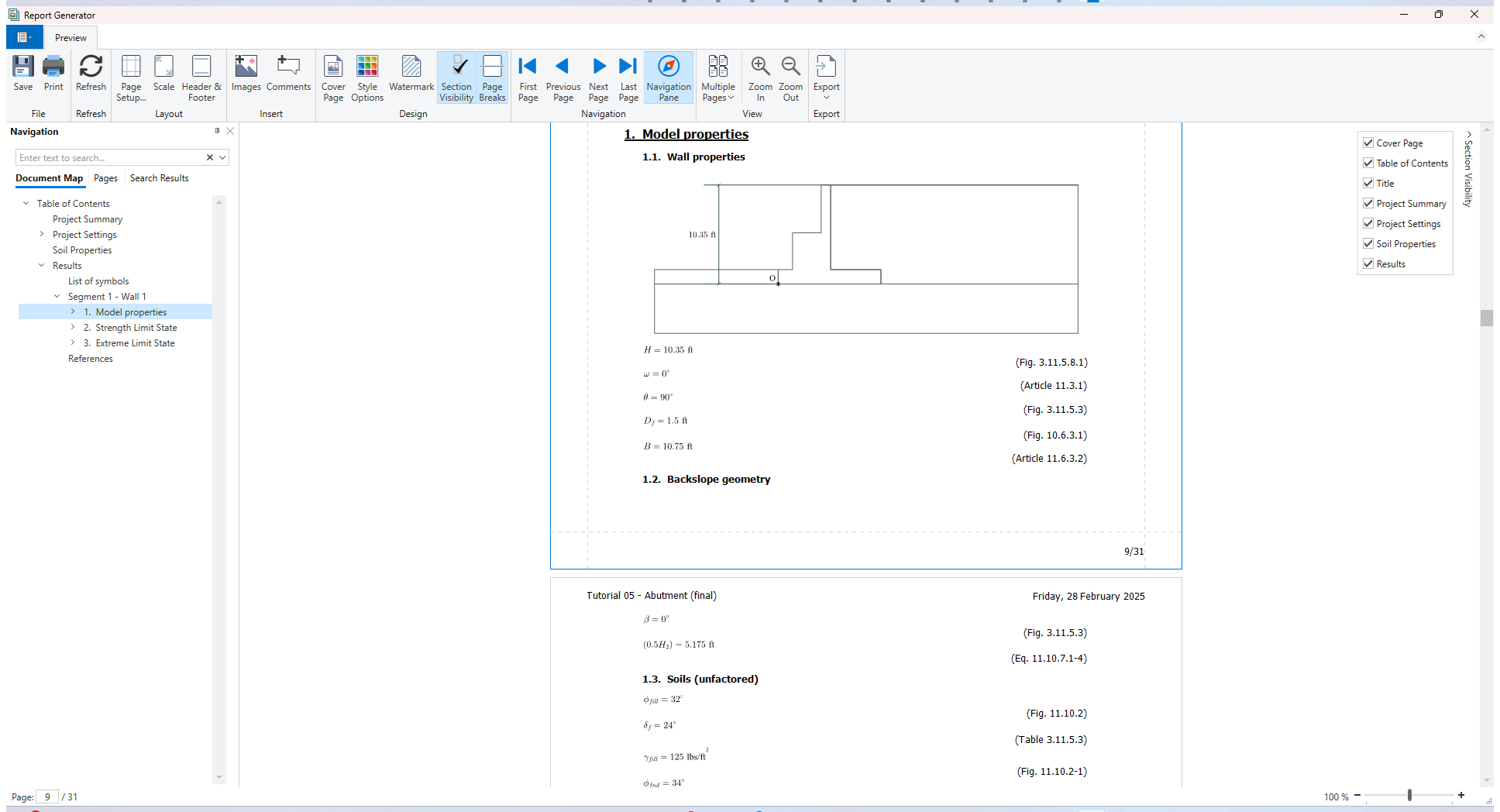
- Select Results > Compute > Report Generator
 to open the Report Generator.
The Report Generator in RSWall provides all the hand calculations for the output results of the RSWall program.
- In the Navigation tree, click on the Results section. At the beginning of the section, the List of symbols used in the analysis is provided.
- For Strength limit state and Extreme Limit state, hand calculations are provided separately.
- Close the Report Generator and return to the Results ribbon.
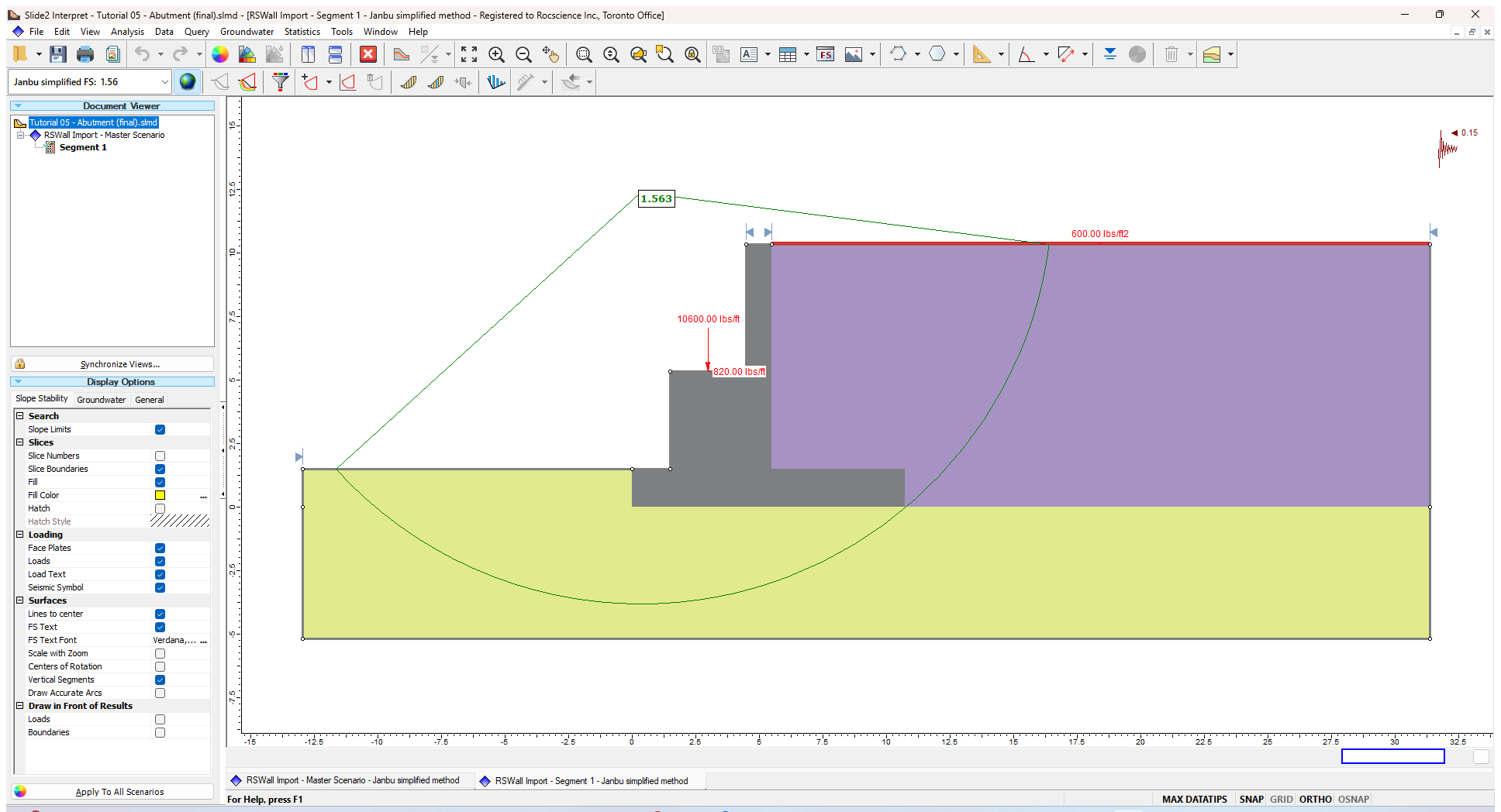
7.0 Slide2 Overall Stability Analysis
- Select Results > Export > Export to Slide2

- Tick the check box for Segment 1.
- Click Open in Slide2 to launch the Slide2 program.
- Save the Slide2 file as “Tutorial 5, Abutment”
- While you are in the Master scenario, select Analysis > Project Settings
 to open the Project Settings dialog.
- In the Methods tab, uncheck Bishop simplified method.
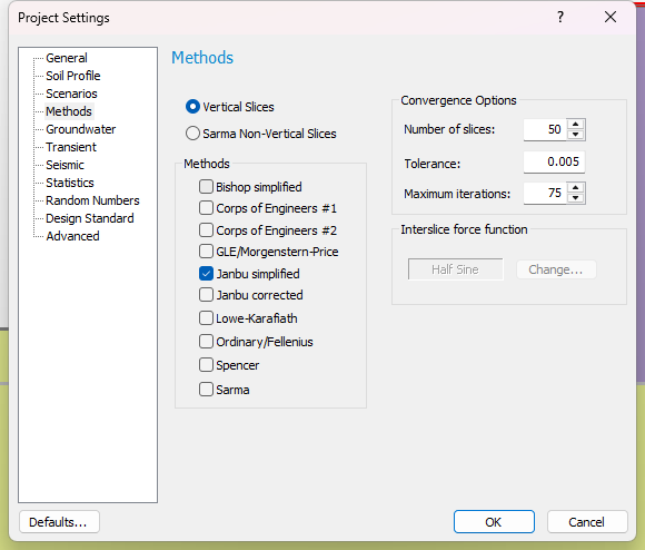
- Click OK to close the dialog.
- In the Methods tab, uncheck Bishop simplified method.
- Select Analysis > Compute
 to compute the model.
 - Select Analysis > Interpret
 to open the Interpreter.

The results are shown as below for Janbu method: