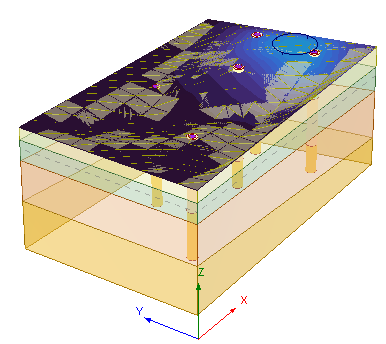
16 - Non-Horizontal Ground Surface
1.0 Introduction
This tutorial demonstrates the Non-Horizontal Ground Surface option in Settle3. This tutorial will walk you through modeling a non-horizontal ground surface and soil profile. Before proceeding with the tutorial, make sure you’ve gone through Tutorial 01 – Settle3 Quick Start Tutorial so you’re familiar with the product’s basic functions and features. You may also wish to go through the Tutorial 13 - Multiple Boreholes tutorial which provides an introduction to modelling a horizontal ground surface with a non-horizontal soil profile, as this tutorial will follow the general procedures of Tutorial 13.
Topics Covered in this Tutorial:
- Non-horizontal soil layers
- Non-horizontal ground surface
- Import surface point cloud data
Finished Product:
The finished product of this tutorial can be found in the Tutorial 16 Non-Horizontal Ground Surface.s3z file. All tutorial files installed with Settle3 can be accessed by selecting File > Recent Folders > Tutorials Folder from the Settle3 main menu.
2.0 Model
2.1 Project Settings
- Select Home > Project Settings
 (CTRL + J) to open the Project Settings dialog.
 - In the General tab, make sure the Stress Units are set as Metric, stress as kPa and the Settlement Units are set to Millimeters.
- Go to the Soil Profiles tab and turn on the Non-Horizontal Layers option.
- Check the Non-Horizontal Ground Surface checkbox, and leave the Surface Interpolation as the default TIN Triangulation option.

- Leave the Number of Surface Points at the default value.
- Click OK to close the dialog.
2.2 Soil Properties
- Select Soils > Define Soil Properties
 (CTRL + 8).
 - For Soil Property 1, select the Immediate Settlement tab and check the box for Immediate Settlement.
- Enter the below data:
- Select the Primary Consolidation tab and set the Material Type as Linear.
- Enter the following values:
- Repeat the above steps for the next two soil layers and enter the data below.
- For Soil Property 4, leave the Immediate Settlement box unchecked.
- Go to the Primary Consolidation tab and set the Material Type as Non-Linear.
- Enter the following values:
- Click OK to close the dialog.
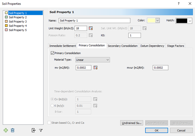
# | Name | Unit Weight (kN/m3) | Es (kPa) | Esur (kPa) |
1 | Sand Fill | 18 | 25000 | 25000 |
mv (m2/kN) | mvur (m2/kN) |
0.0002 | 0.0002 |
# | Name | Unit Weight (kN/m3) | Es (kPa) | Esur (kPa) | mv (m2/kN) | mvur (m2/kN) |
1 | Sand Fill | 18 | 25000 | 25000 | 0.0002 | 0.0002 |
2 | Silty Sand | 18 | 20000 | 20000 | 0.0002 | 0.0002 |
3 | Dense Silty Sand | 19 | 25000 | 25000 | 0.0002 | 0.0002 |
# | Name | Unit Weight (kN/m3) | Es (kPa) | Esur (kPa) | Cc | Cr | e0 | OCR |
4 | Silty Clay | 18 | - | - | 0.38 | 0.01 | 1.1 | 0.7 |
2.3 Add Boreholes
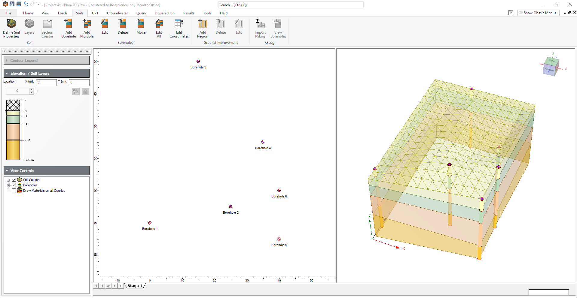
- Select Soils > Add Borehole
 .
. - The Edit Borehole dialog will open. Click on the Insert Layer Below button three times. The layers will fill in with the correct names automatically.
- Specify the layer thicknesses and Borehole Top Elevation as shown below.
- Click on the
 icon to add another borehole. Notice that the first borehole is copied in Borehole 2.
 - Define the other boreholes using the tables below.
- Click OK to close the dialog.
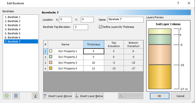
# | Name | Thickness | Top Elevation | Bottom Elevation |
1 | Sand Fill | 3 | 3 | 0 |
2 | Silty Sand | 5 | 0 | -5 |
3 | Dense Silty Sand | 10 | -5 | -15 |
4 | Silty Clay | 12 | -15 | -27 |
Borehole Name | Borehole Location | Borehole Top Elevation | |
X | Y | ||
Borehole 2 | 25 | 5 | 7 |
Borehole 3 | 15 | 20 | 2 |
Borehole 4 | 35 | 25 | 1 |
Borehole 5 | 40 | -5 | 7 |
Borehole 6 | 40 | 10 | 7 |
Thickness | |||
Material | Boreholes 2, 5, 6 | Borehole 3 | Borehole 4 |
Sand Fill | 5 | 4 | 4 |
Silty Sand | 6 | 7 | 8 |
Dense Silty Sand | 12 | 8 | 10 |
Silty Clay | 7 | 11 | 8 |
3.0 Loads
- Select Loads > Circular Load
 (CTRL + 2) to add a circular load.
 - Change the Bottom Elevation to 4m. Keep all other values as default.
- Click OK to close the dialog.

You can specify the load location using your mouse to click on the location plan view, or you can type the coordinates into the field in the lower right of the screen. Set the load location as as (40,0).
4.0 Field Point Grids
With the Non-Horizontal Ground Surface Option two field point grids can be defined:
- Field Point Grid
- Non-Horizontal Field Points
The Field Point Grid is the standard rectangular field point grid, whereas the Non-Horizontal Field Points Grid is a 3D surface contour for the ground surface.
4.1 Field Point Grids
- Select Query > Auto Field Point Grid
 . The Grid Properties dialog will appear.
 - Keep the default values and click OK to apply the field point grid.
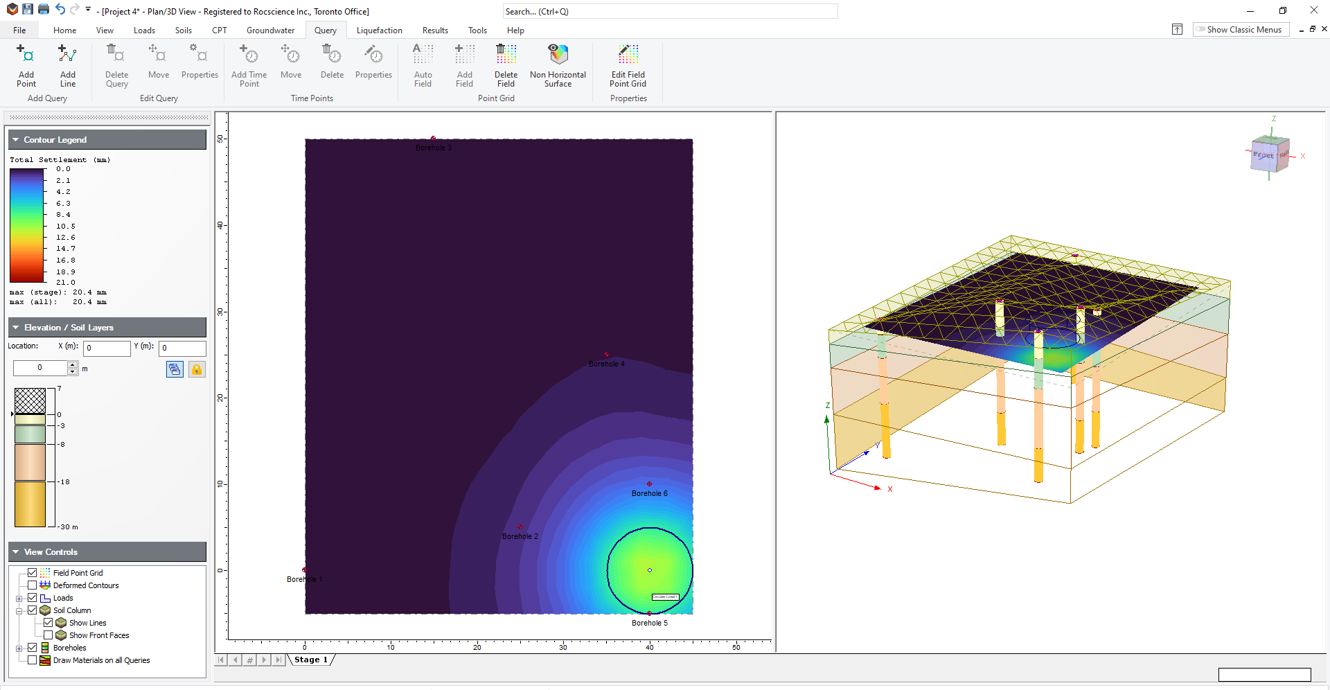
- Use your mouse to move the field point grid up and down. You can do so by either clicking on the 3D view or dragging the arrow up and down the Elevation / Soil Layers control.
As you move the field point grid up, you can see the contours are only shown in areas where there is ground.
To turn off the Field Point Grid:
Uncheck the Field Point Grid checkbox in the right-side View Controls.

4.2 Non-Horizontal Field Points
- Select Query > Non-Horizontal Surface

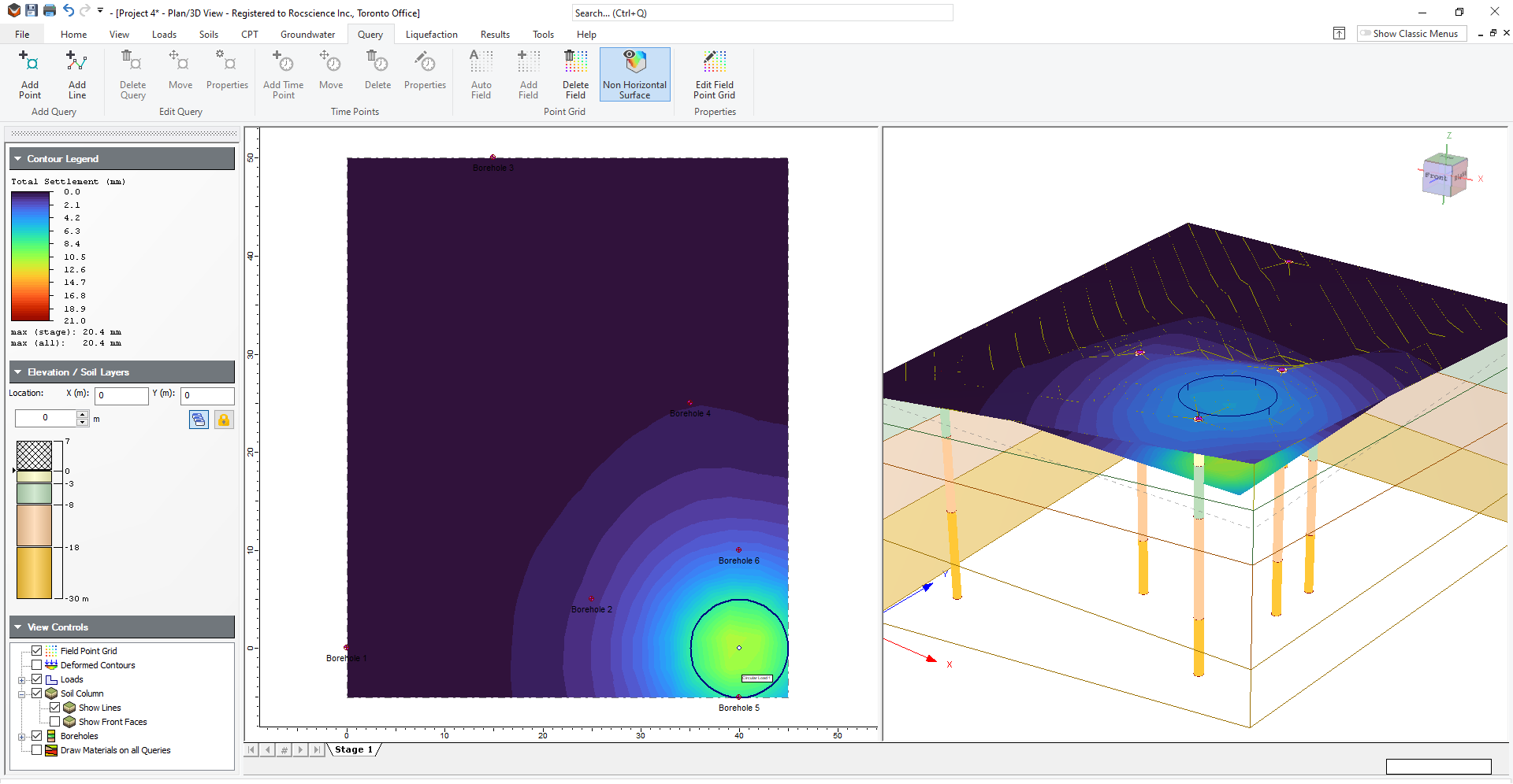
You should see the Total Settlement Contours along the top surface of the model.
5.0 Additional Exercise
Non-horizontal ground surfaces can also be generated by importing surface point-cloud data. In this exercise, we will import surface point cloud data in addition to the existing boreholes in this tutorial.
5.1 Enabling Surface Point Cloud Import
- Select Home > Project Settings
 and go to the Soil Profile tab.
 - Select Layer Options = Non-Horizontal Soil Layers.
- Tick the checkbox for Non-Horizontal Ground Surface.
- Select Surface Data Source = Point cloud.
- Click OK
The Import Surface Points button will now be enabled.
5.2 Importing Surface Point Cloud Data
Surface point cloud data can be imported using a spreadsheet (*.xlsx) or a comma-separated values file (*.csv). For this additional exercise, you can create a spreadsheet with the values shown in the table. The first row should be reserved for column headers (e.g., X, Y, Z) and should not contain point cloud data.
| X | Y | Z |
| -15 | -5 | 5 |
| -15 | 10 | 5 |
| 0 | -10 | 0 |
| 0 | 15 | 0 |
| 5 | -10 | 0 |
| 5 | 15 | 0 |
| 20 | -5 | 0 |
- Select Soils > Import Surface Points

- Select the Excel spreadsheet containing point cloud data.
- Click Open
The ground surface will now be constructed from the boreholes and the imported surface point cloud data points.
