Open Pit Stability Analysis
1. Introduction
This tutorial will demonstrate how an open pit mine can be modelled by importing surface and sub-surface geometry from DXF and STL files.
Select File > Recent > Tutorials and read in the file Open Pit Stability Analysis – starting file from the installation folder.
This file contains all of the required material properties but does not contain the model geometry.
2. Import DXF
 Select Geometry > Import/Export > Import Geometry
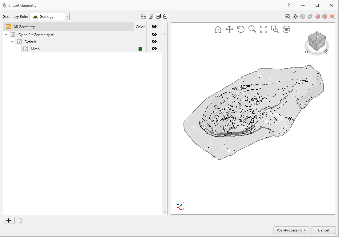
The ground surface and pit geometry have been stored in an *.STL file. Open the file 'Open Pit Geometry.stl' (3D Object).
Select the All Geometry box in the Import Geometry dialog.
Make sure the checkbox next to each layer is selected as shown in the dialog. You should see the following:
Select Post-Processing.
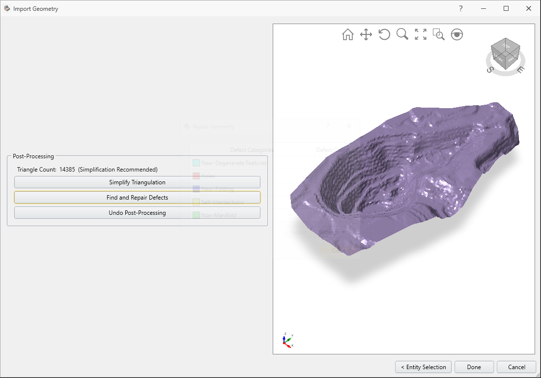
Select Find and Repair Defects. Click Repair and then Close.
For this tutorial, we will only use the Find and Repair Defects button. Note that it is good practice to use both Simplify Triangulation and Find and Repair Defects buttons when importing complex geometry.

Select Done to import the file Open Pit Geometry.stl.
 Select the Geometry > Import/Export > Import Geometry option again and import the files Open Pit Layer1.dxf and Open Pit Layer2.dxf by selecting both at the same time.
You should see two more surfaces representing the boundaries between material regions.
Once again select the All Geometry checkbox as shown:

Press Post-processing and Select Find and Repair Defects. As before, select Repair and then Close.

Select Done.
3. Create External Volume
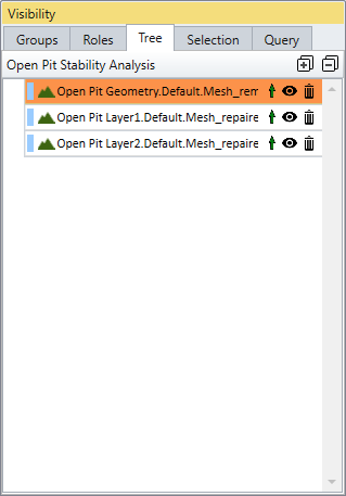
In the sidebar Visibility pane, select the first entity at the top of the list (Open Pit Geometry). This is the pit surface imported from the STL file.
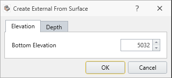
From the Geometry menu, select the Create External from Surface option. Select OK without changing the default values in Create External from Surface dialog.
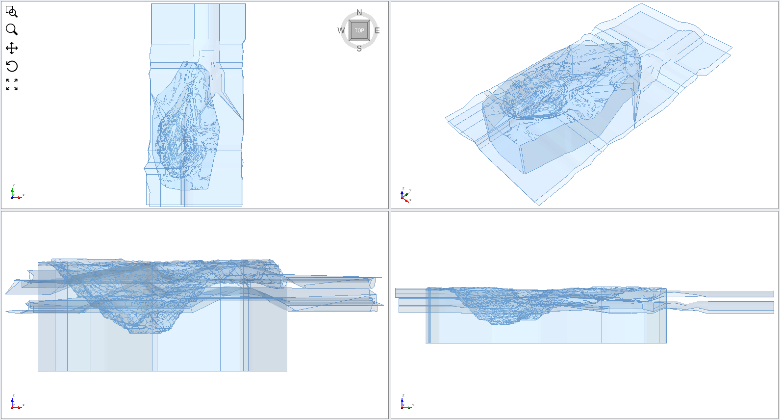
The External Volume should be created by extruding downwards from the outer perimeter of the pit surface geometry as shown:
3.1 DIVIDE ALL
 Select Geometry > 3D Boolean > Divide All Geometry
Select OK in the dialog to use the default quality.
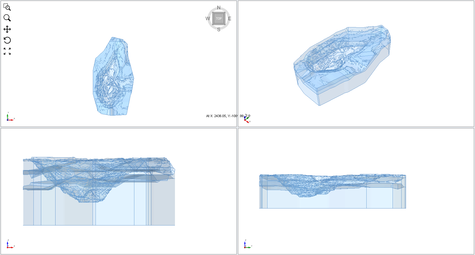
This will intersect the two material surfaces with the External Volume. The model should appear as follows:
4. Assign Materials
In the sidebar Visibility pane you should see the following entities:
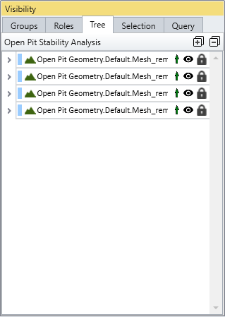
The Divide All operation has created an External Volume which consists of four different volume regions. We need to assign the correct material properties to each external volume region.
Note: In the below steps, the model layer order may differ in your visibility pane depending on the order of the layer import or extrusion.
We will be assigning Limestone to the top layer (two volume pieces), Ore to the second layer (one volume piece), and Sandstone to the bottom layer.
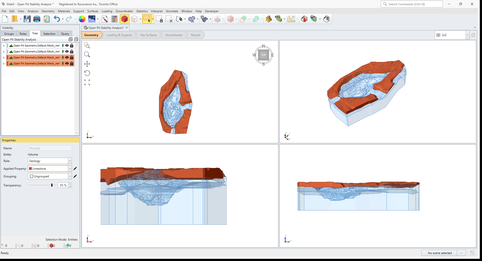
- Click on the entity in the visibility tree list that highlights one of the two top layer pieces. In the Properties pane, notice that the default material assignment is Sandstone. Change the Applied Property to Limestone.
- Click on the other top layer volume piece in the list and also assign the Limestone material property. We have now assigned Limestone to the upper material layer of the model.
- Click on the entity that highlights the second layer and assign the Ore material.
- Click on the entity that highlights the bottom layer. This is already assigned the default Sandstone assignment, which is correct, so you do not have to change the material assignment.
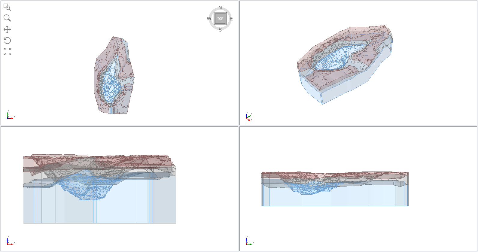
The material assignments are complete. Save the file with a new file name. The model should appear as follows:
4.1 ASSIGN MATERIALS USING A CUTTING PLANE
We will now mention an alternative method of assigning materials which can be very useful for assigning material properties to complex 3D models.
Select Materials > Assign Materials Using Cutting Plane
You will see the following dialog, and a moveable cutting plane will be displayed in the model view.

This dialog can be used as an alternative way of assigning the material properties via the use of cross sections.
5. Slip Surface Options
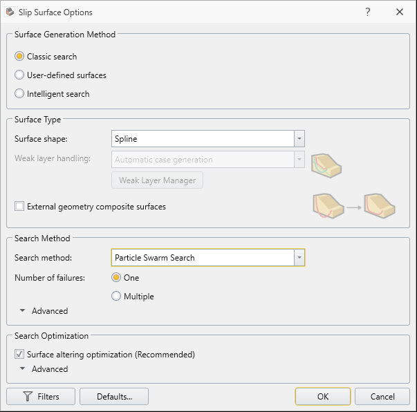
We will use following settings in the Slip Surface dialog:
- Select Surfaces > Slip Surface Options

- Select:
- Surface Generation Method = Search Method
- Surface Type = Spline
- External Geometry Composite Surfaces = OFF
- Search Method = Particle Swarm Search
- Surface Altering Optimization = ON
6. Compute
Save the model.
 Select Analysis > Compute
Both Janbu and GLE analysis methods have been selected in Project Settings. The analysis should take a few minutes.
7. Results
 Select the Results workflow tab
Select Show Contours. You should see the following:
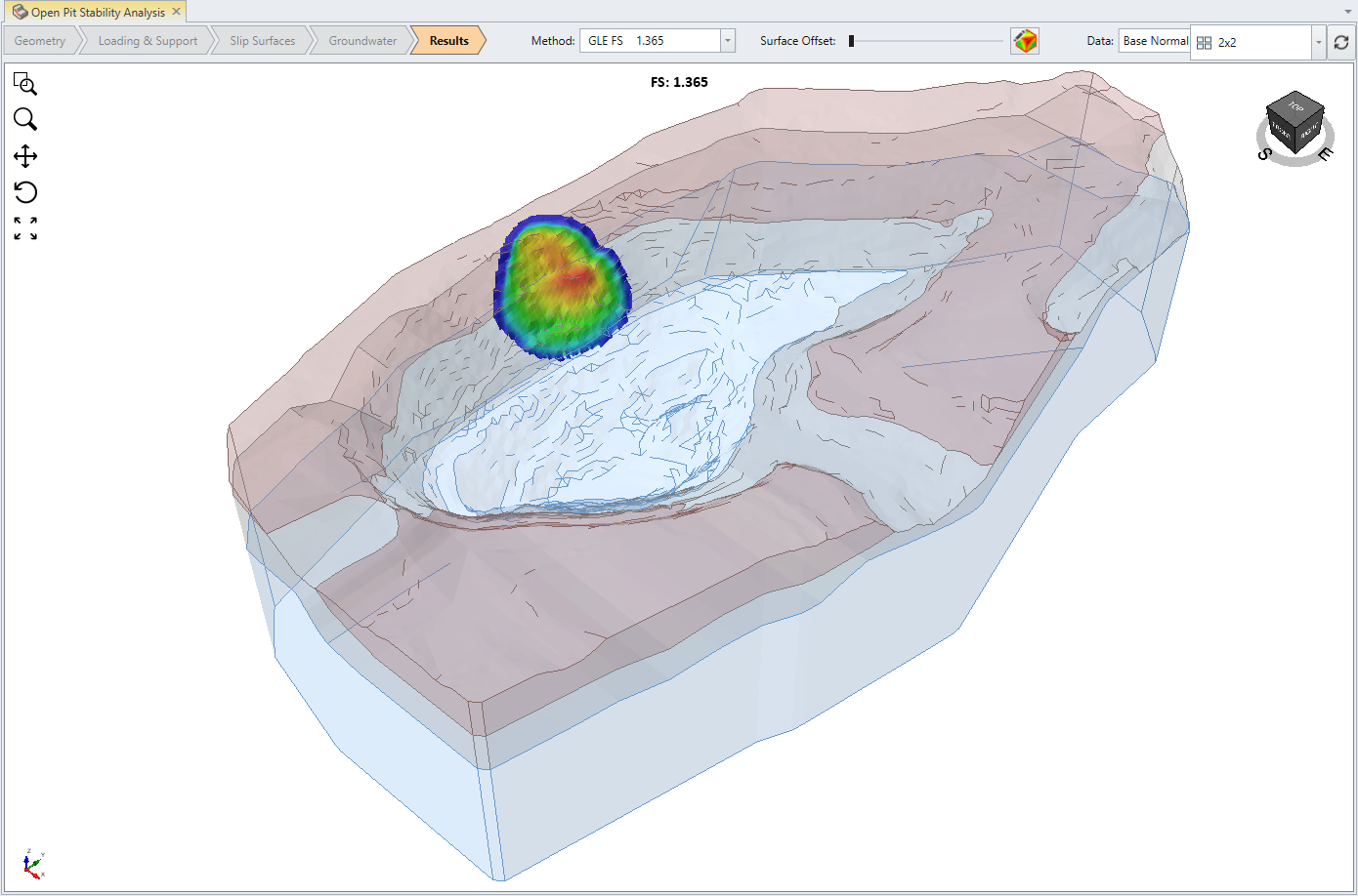
The safety factor of the critical slip surface using the GLE analysis method is shown above.
8. Creating a Safety Map
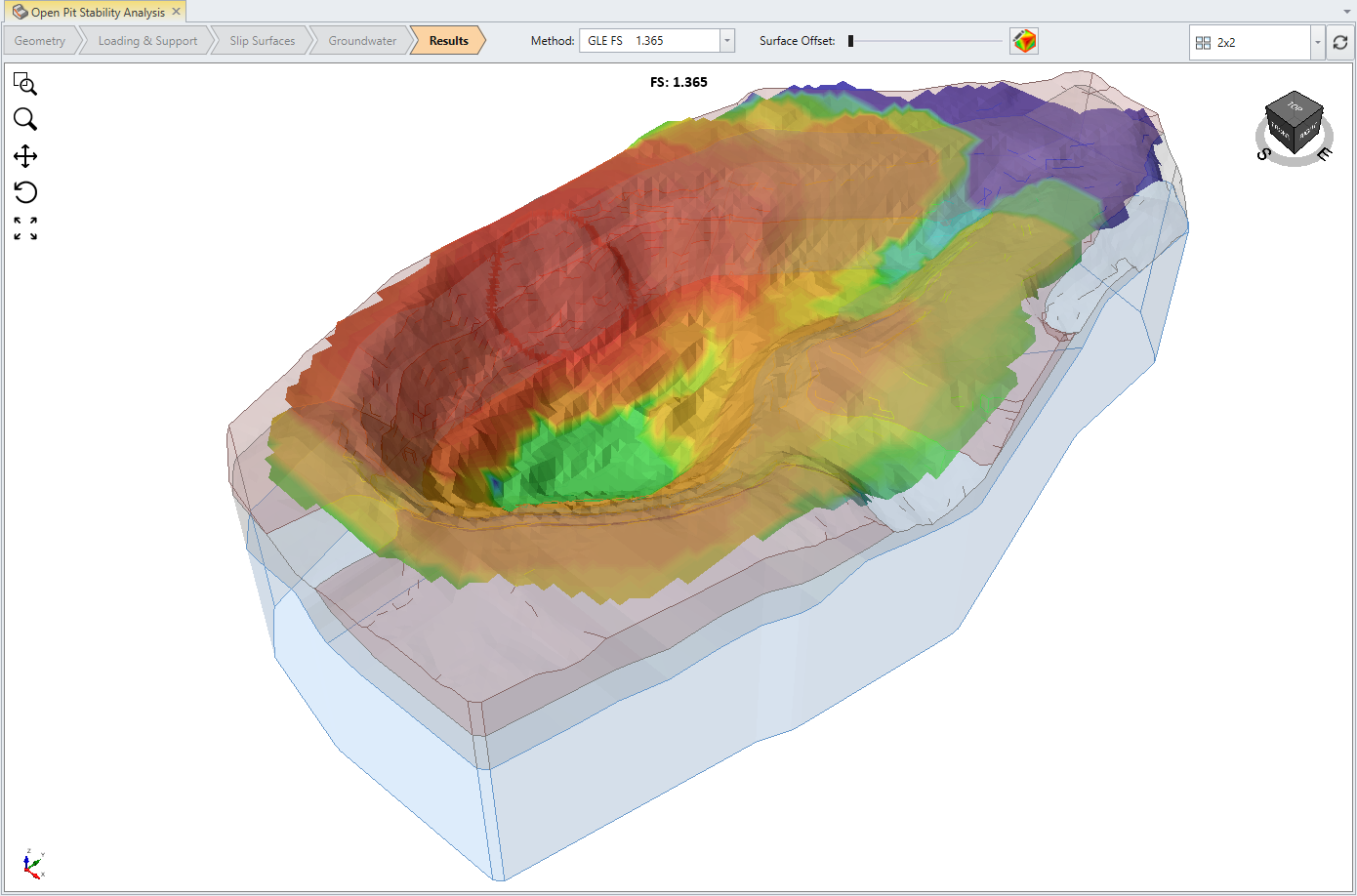
We will create a safety map of the results.
Select Interpret > Add Surface Safety Map
By selecting this feature, you can see the safety map of the computed model.
9. Additional Exercise I: Search Limits
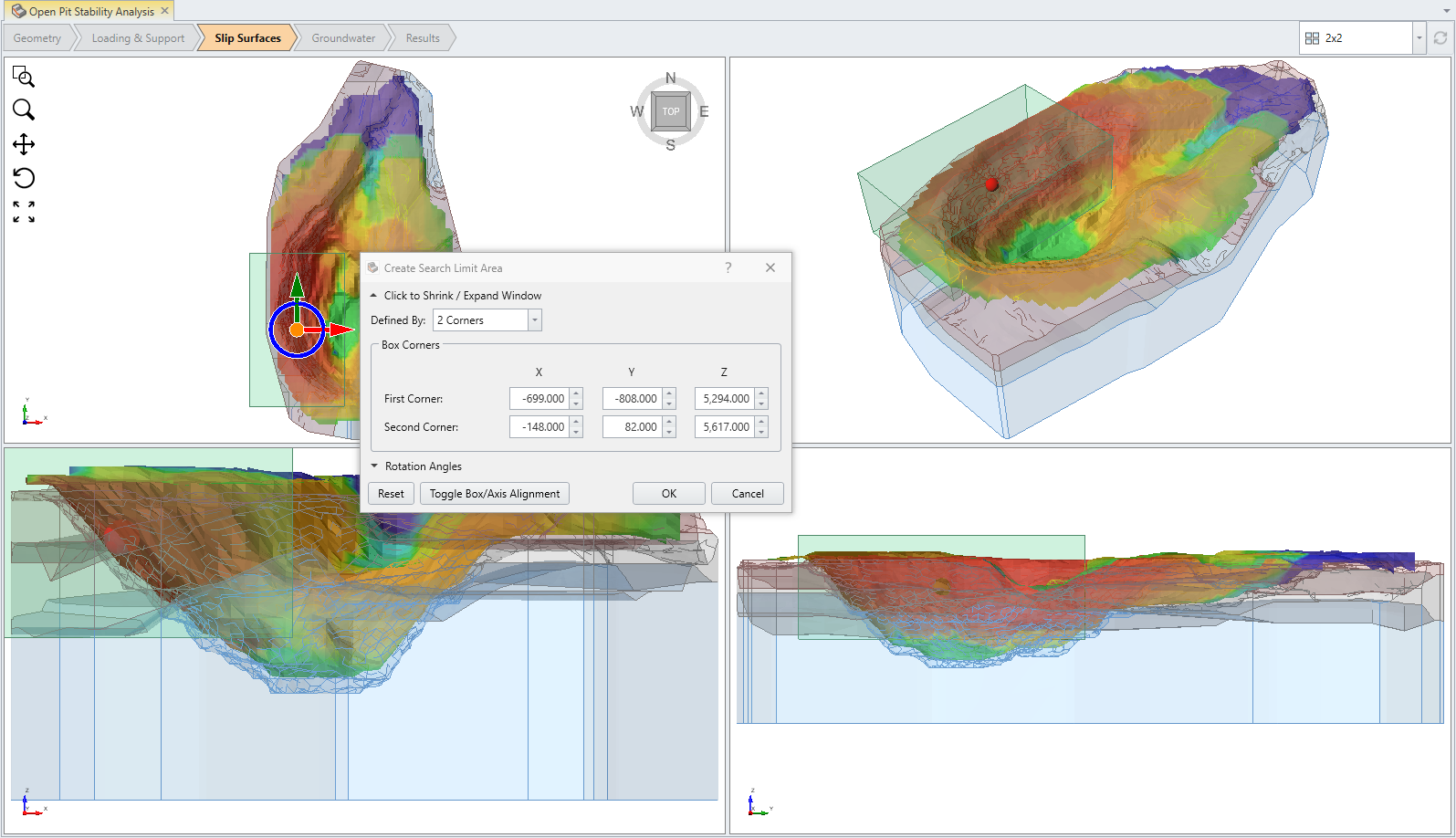
As an additional exercise, use the search limits option to define a volumetric box which limits the search area to one side of the open pit. Re-run the analysis and compare the result.
Select: Surfaces > Add Search Limit > Add Search Limit by Box
You will then be prompted to define the search area of interest. Select the area in RED, having the minimum safety factor, OR enter the following XYZ values:
