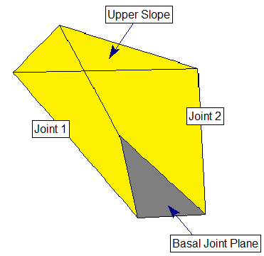
Basal Joint Plane
The Basal Joint option allows you to include a THIRD joint plane in the SWedge analysis, which allows you to analyze 5-sided (pentahedral) wedges as illustrated in the figure below.
To include a basal joint:
- In the Project Settings dialog, under the General tab, select the Block Shape = Basal Joint option.
- You will notice the wedge now includes a third (basal) joint plane.
- The Input Data dialog will now allow you to enter orientation and strength data for the basal joint plane, in addition to the Joint 1 and Joint 2 planes.

Basal Joint Properties
Basal joint properties are defined in the same manner as the Joint 1 and Joint 2 planes. For more information see:
Basal Joint Tutorial
See the Basal Joint Tutorial for an introduction on how to include a basal joint in the analysis. The tutorial also discusses some differences in the availability of analysis options for basal joint wedges compared to tetrahedral wedges.
Basal Joint Wedge with Tension Crack
A tension crack can be included with a basal joint wedge, however, note that the definition of the distance from crest is not the same as the definition for a tetrahedral wedge. See the Basal Joint Wedge document for details.
Limitations of Basal Joint Analysis
Most analysis options which are available for tetrahedral wedges in SWedge are also applicable to basal joint wedges. There are a few exceptions, however:
- The Bench Design option cannot be used with basal joint wedges, and is only applicable for tetrahedral wedges
- If a Tension Crack is included, you must specify the location of the tension crack. The Minimum FS Location and Use Bench Width to Maximize options are not available.
In general, you may notice a few differences in available options, and how they work depending on the block shape (tetrahedral or basal joint).