Input Data Overview
SWedge computes the Factor of Safety for the translational slip of a tetrahedral wedge formed in a rock slope by:
- two intersecting discontinuities (joint sets),
- the slope face, and
- the upper ground surface.
Additional planes (tension crack / basal joint) allow you to analyze more complex wedge shapes by applying:
- tension crack (optional)
- basal joint plane (optional)
Typical SWedge problem geometry is illustrated in the figure below.
| LEGEND 1, 2 = Failure planes (2 intersecting joint sets) 3 = Upper ground surface 4 = Slope face 5 = Tension crack H1 = Slope height referred to plane 1 L = Distance of tension crack from the crest, measured along the trace of plane 1. |
Typical wedge geometry for SWedge analysis (tetrahedral wedge with tension crack) [Hoek & Bray (1981)].
When a pair of discontinuities is selected at random from a set of field data, it is not known whether:
- The planes could form a wedge (the line of intersection may plunge too steeply to daylight in the slope face or it may be too flat to intersect the upper ground surface).
- One of the planes overlies the other (this affects the calculation of the normal reactions on the plane).
- One of the planes lies to the right or the left of the other plane when viewed from the bottom of the slope.
In order to resolve these uncertainties, the solution has been derived in such a way that:
- Either of the planes may be labelled 1 (or 2).
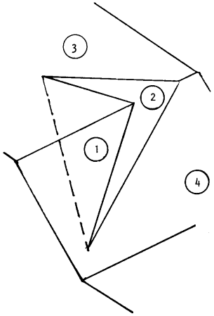
- Allowance has been made for one of the planes overlying the other (this is illustrated in the next figure).
- The crest can overhang the base of the slope.
- Contact may be lost on either plane (this is dependent on wedge geometry, and also on the magnitude of the water pressures acting on the planes).
A check on whether the two planes do form a wedge is included in the solution at an early stage. In addition, SWedge also examines how the tension crack intersects the other planes, accepting only those cases where the tension crack truncates the wedge in a kinematically admissible manner.

Wedge with Basal Joint
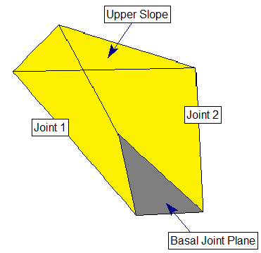
If the Basal Joint option is enabled, SWedge allows you to define an additional (third) joint plane referred to as the basal joint, as illustrated in the figure below. This allows you to analyze five-sided (pentahedral) wedges formed by the intersection of three joint planes and the two slope planes. An optional tension crack can also be defined for basal joint wedges, in the same manner as described above for tetrahedral wedges.
See Block Shape Setting in SWedge and Basal Joint Plane Properties in SWedge for further information.

