15 - Tunnel Orientations Analysis
1.0 Introduction
This tutorial demonstrates the features of the Tunnel Orientation Analyzer in UnWedge.
The Tunnel Orientation Analyzer is essentially an automation tool which can analyze a range of tunnel axis trends and plunges, as well as consider all possible joint combinations. From these computations, UnWedge is able to determine critical minimum or maximum values (i.e., Required Support Pressure, Factor of Safety, Wedge Weight, etc.) and the tunnel trend, plunge, and joint combination to produce these critical conditions.
Topics Covered in this Tutorial:
- Deterministic Joint Combinations Analysis
- Find Critical Joint Combinations and Tunnel Orientations
- Find Critical Minimum and Maximum Required Support Pressure
- Find Critical Minimum and Maximum Factor of Safety
Finished Product:
The finished product of this tutorial can be found in the Tutorial 15 Tunnel Orientations Analysis.weg5 file, located in the Examples > Tutorials folder in your UnWedge installation folder.
2.0 Model
- If you have not already done so, run the UnWedge program by double-clicking the UnWedge icon in your installation folder or by selecting Programs > Rocscience > UnWedge > UnWedge in the Windows Start menu. When the program starts, a default model is automatically created.
If the UnWedge application window is not already maximized, maximize it now so that the full screen is available for viewing the model.
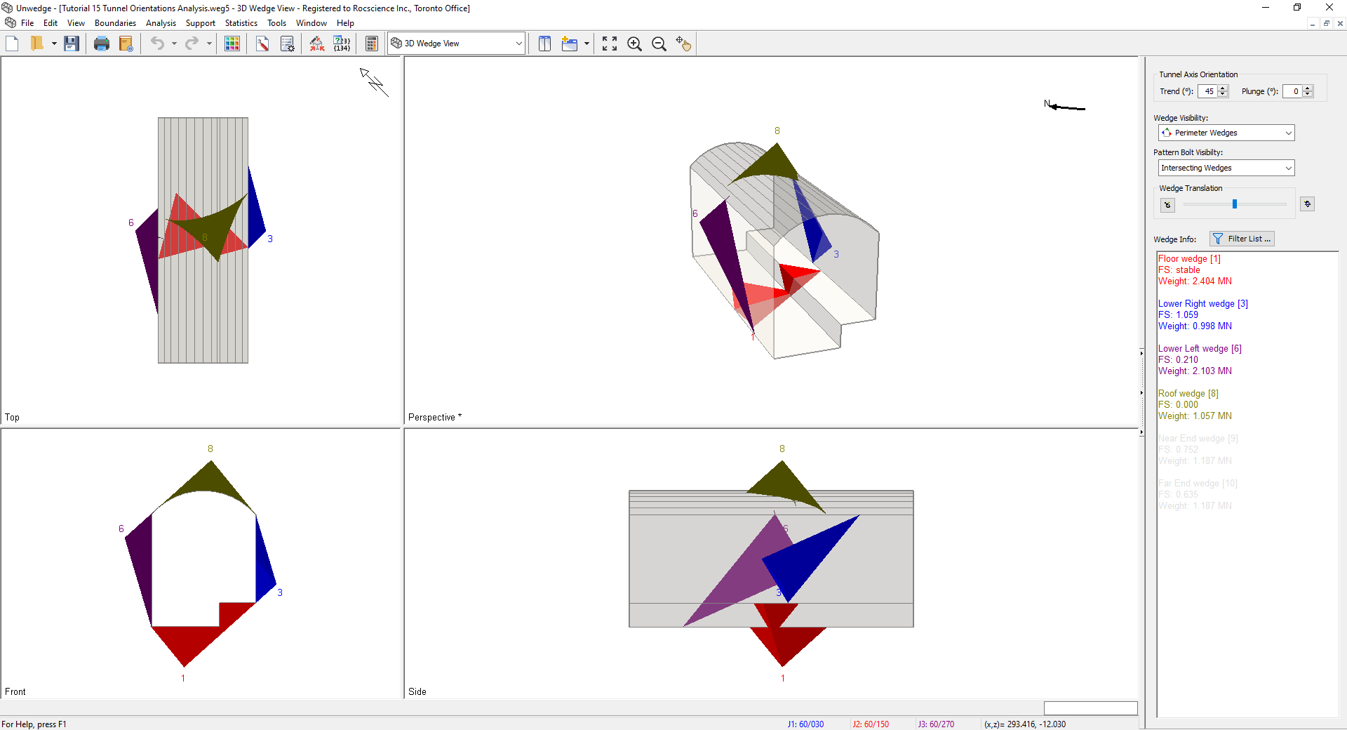
For this tutorial, we will start by reading in the file Tutorial 15 Tunnel Orientations Analysis.weg5 which you should find in the Examples > Tutorials folder in your UnWedge installation folder. The model is Deterministic and contains both perimeter and end supports.
- Select File
 > Recent Folders > Tutorials Folder.
 - Open the Tutorial 15 Tunnel Orientations Analysis file.
You should see the following view.

3.0 Joint Combinations
We will start by examining the number of possible joint combinations.
- Select Analysis > Combination Analyzer.
- Set Sort By = Required Support Pressure, Then By = Factor of Safety.
- Set Wedge Selection = All Wedges.
- Select Compute Combinations

- Select OK to close the Combination Analyzer dialog.

There are 10 possible joint combinations formed by the 5 joints defined in the Input Data dialog. At the current Tunnel Axis Orientation (Trend = 45 deg, Plunge = 0 deg), Joints 1, 2, 4 produce the maximum Required Support Pressure, while Joints 1, 3, 5, and Joints 2, 3, 4 produce the minimum Required Support Pressure. This dialog provides us information about the global Required Support Pressure and Factor of Safety for all joint combinations but only for one tunnel orientation.
4.0 Tunnel Orientation Analyzer
What if we want to find the worst-case scenario tunnel orientation, given multiple joint combinations? We must consider a range of tunnel trends and plunges, as well as all joint combinations.
To start performing a tunnel orientation and joint combinations analysis:
- Select Analysis > Tunnel Orientation Analyzer
 .
. - The Tunnel Orientation Analyzer dialog will appear allowing you to specify:
- Critical Data Type
- Critical Value
- Tunnel Axis Trend and/or Plunge
- Wedge Selection
- Consider All Joint Combinations

4.1 WORST CASE SCENARIO
Let's say we want to find the tunnel orientation and joint combination producing the minimum Factor of Safety between all 10 wedges (8 Perimeter Wedges, 2 End Wedges) forming on the tunnel. This may be desirable in order for us to identify the scenarios to avoid.
In the Tunnel Orientation Analyzer dialog:
- Set Data Type = Min. Factor of Safety.
- Set Critical Value = Minimum. This will find the critical minimum of the Minimum Factor of Safety between the selected wedges.
- Set Tunnel Axis = Trend and Plunge. Both trend and plunge will be varied.
- Enter Trend Min = 0 deg, Trend Max = 360 deg, Trend Num. Intervals = 36.
- Enter Plunge Min = 0 deg, Plunge Max = 90 deg, Plunge Num. Intervals = 9.
- Set Wedge Selection = All Wedges.
- Select Consider All Joint Combinations. This will perform the analysis over all possible joint combinations, and not just the currently selected combination.
- Select Compute Critical Orientations to analyze the selection and populate the list.
- Select OK to close the dialog.


As you can see from the list, multiple joint combinations and tunnel orientations can produce a Min. Factor of Safety of 0.00000.
Likewise, if we wanted to look at the worst-case scenario for required support pressure, we could set the Data Type = Max. Pressure for FS. = 1.000. and set the Critical Value = Maximum. This would help us identify which scenario would result in the highest support costs.
5.0 Tunnel Axis Plot
What if we want to find the best-case scenario tunnel orientation, given multiple joint combinations?
To start performing a tunnel orientation and joint combinations analysis:
- Select Analysis > Tunnel Axis Plot Settings.
- The Tunnel Axis Plot Settings dialog will appear allowing you to specify:
- Plot Tunnel Axis
- Range of Trend and/or Plunge
- Number of Intervals for Plot Generation
- Wedges to Analyze
- Consider All Joint Combinations
5.1 BEST CASE SCENARIO
In the Tunnel Axis Plot Settings dialog:
- Set Plot Tunnel Axis = Trend and Plunge.
- Set Tunnel Axis = Trend and Plunge. Both trend and plunge will be varied.
- Enter Trend Min = 0 deg, Trend Max = 360 deg, Trend Num. Intervals = 36.
- Enter Plunge Min = 0 deg, Plunge Max = 90 deg, Plunge Num. Intervals = 9.
- Set Wedge Selection = All Wedges.
- Select Consider All Joint Combinations. This will perform the analysis over all possible joint combinations, and not just the currently selected combination.
- Select OK to save the settings and close the dialog.
- Switch to Tunnel Axis Plot
 view.
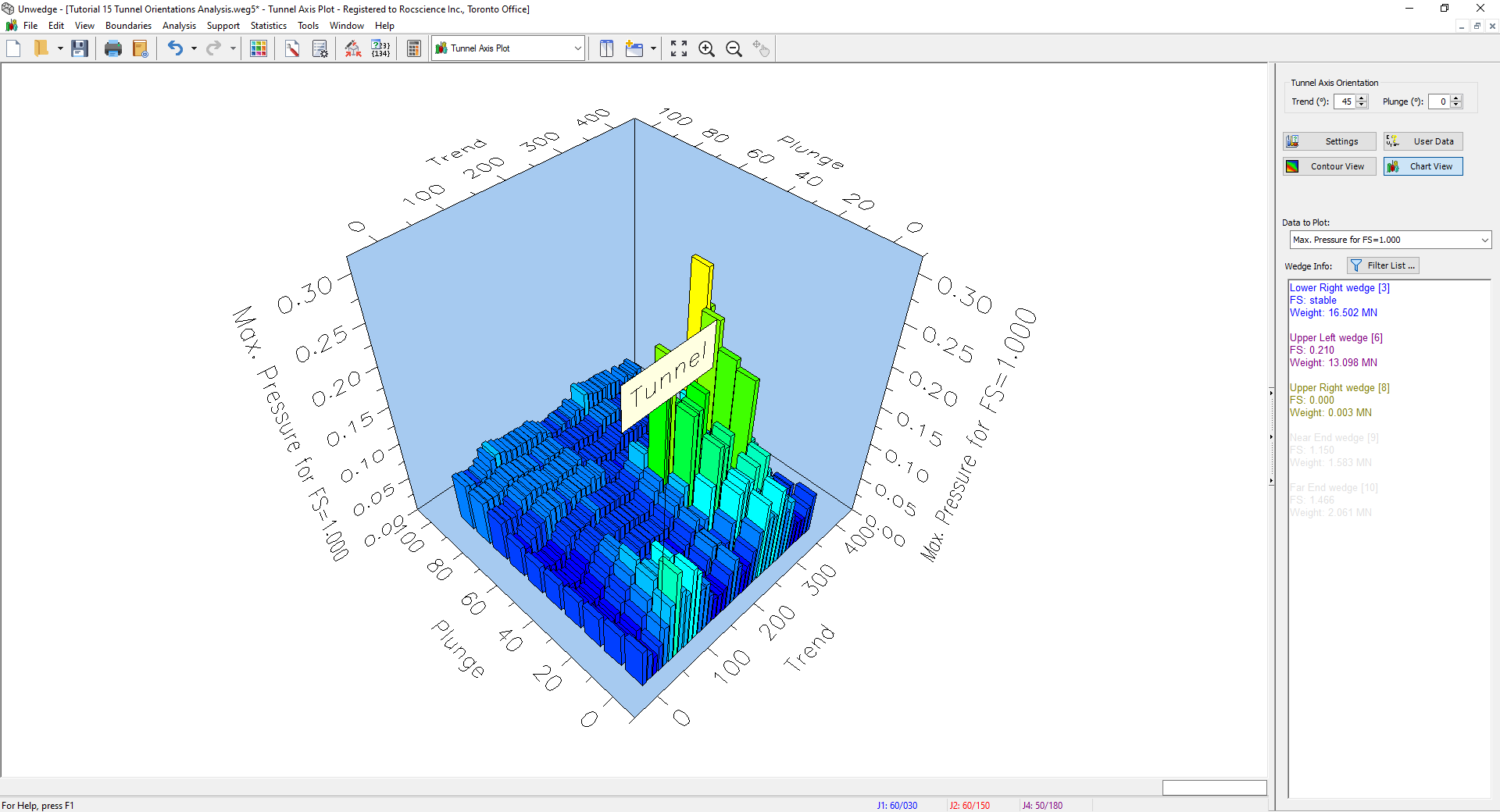
view. - Set Data to Plot = Max. Pressure for FS = 1.000 in the Sidebar.


From the 3D Tunnel Axis Plot, you can easily identify which tunnel orientations require the least support and which ones require the most support, taking into account all possible joint combinations.
This concludes the tutorial. You are now ready for the next tutorial, Tutorial 16 - Truncation Surface and Planes in UnWedge.