Can Secondary Toppling Failure Analysis Save Cappadocia’s Ignimbrites?
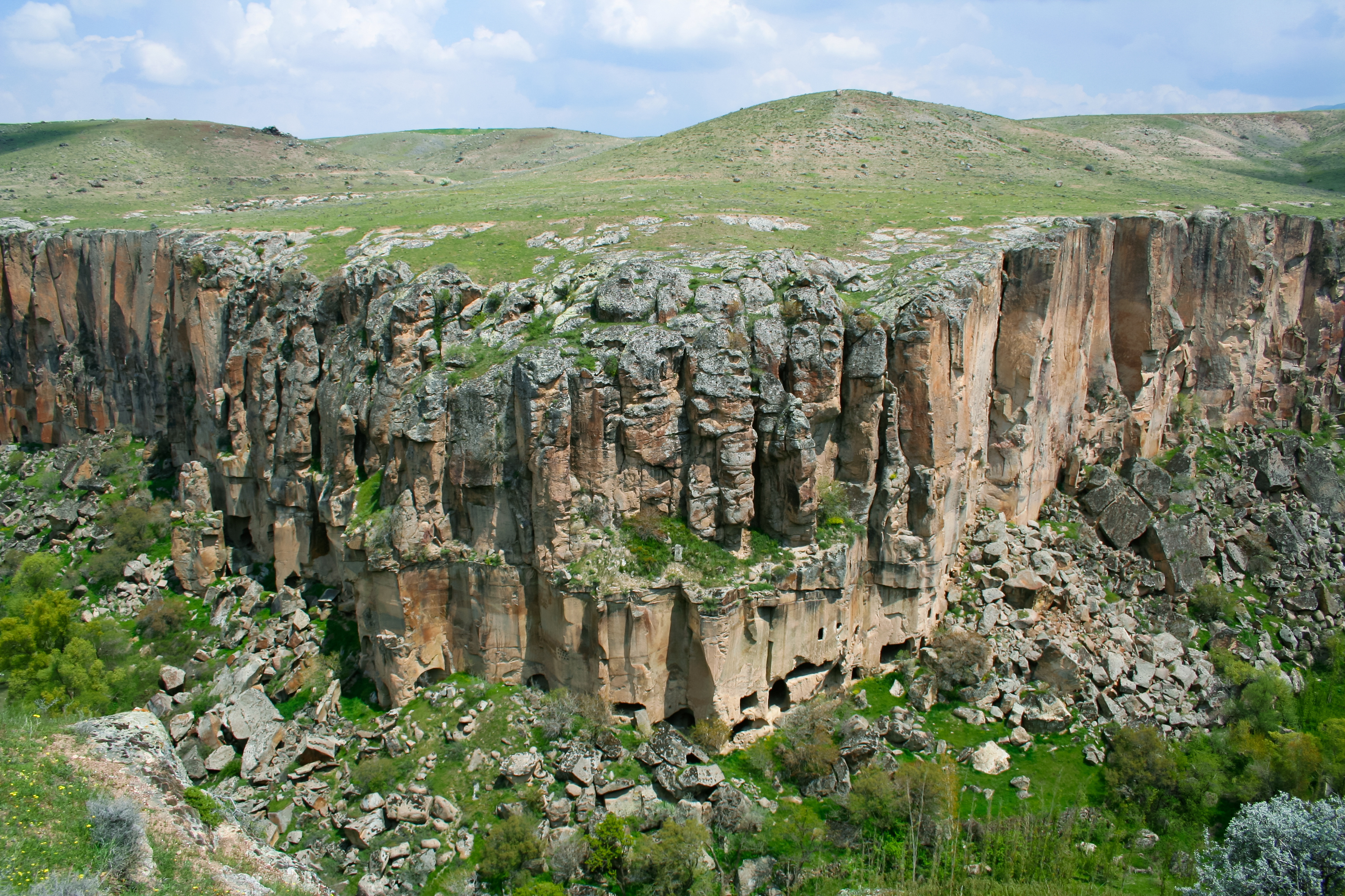
The Ihlara Valley in the heart of Cappadocia, Türkiye, captivates visitors with its ancient dwellings and churches carved into rock. However, the valley's beautiful cliffs, made of Kizilkaya ignimbrite, are vulnerable to secondary toppling failures.
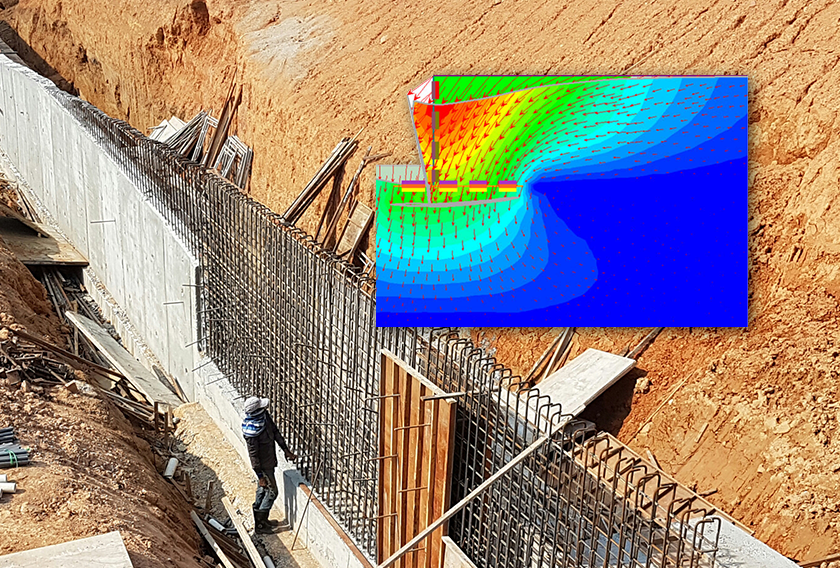
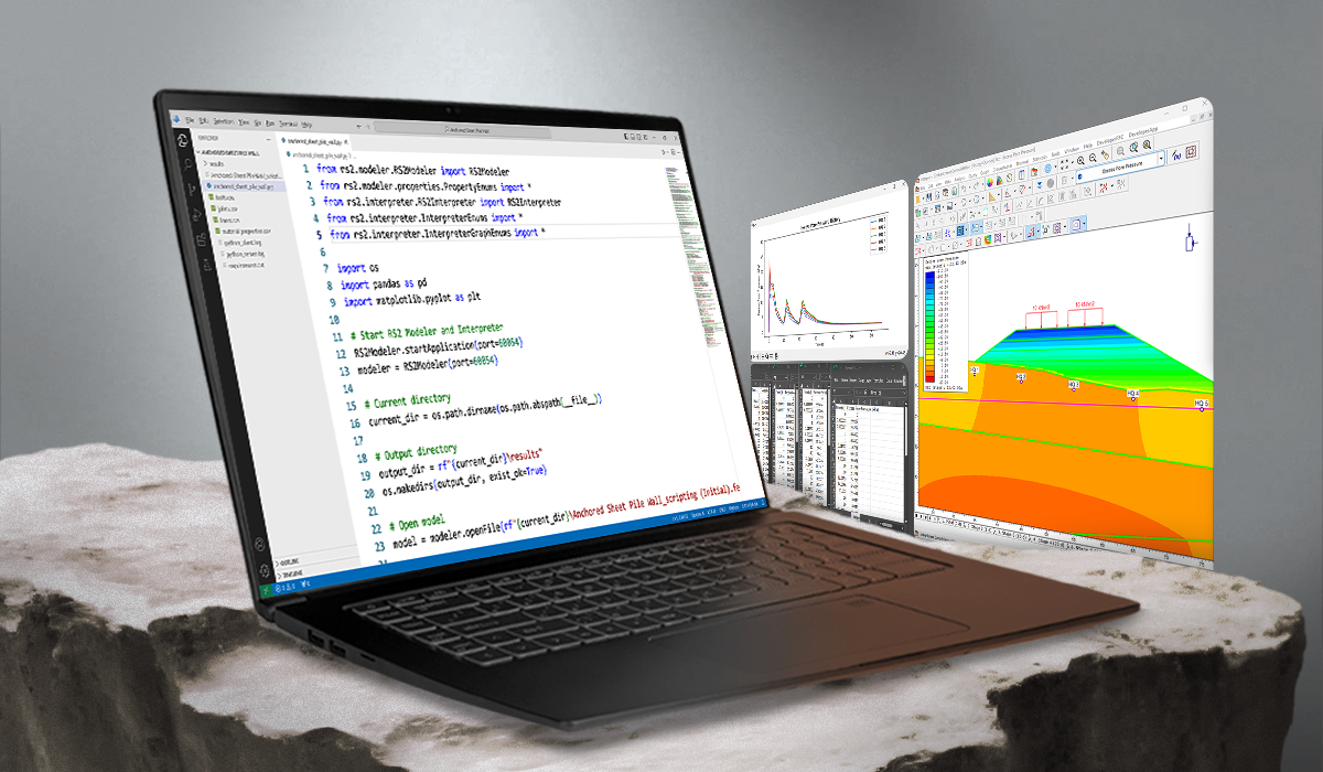
These instabilities pose threats to visitor safety and the preservation of cultural heritage sites. It’s vital to address the hazards, and advanced geotechnical engineering tools like DIPS and RS2, one of our finite element method (FEM) programs, offer a reliable solution.
Here, we’ll show how researchers used the software’s numerical modeling, along with thorough field investigations, to understand why these cliffs fail and how to stabilize them effectively. The goal was to learn how to protect visitors and ensure the long-term preservation of the valley’s unique geological and cultural assets.
You can also read Mehmet Sari’s research paper for deeper insights.
The Geological Setting
The Ihlara Valley is in the Central Anatolian volcanic province, bordered by Mt. Erciyes and Mt. Hasan. The valley's stratigraphy includes Tertiary-Quaternary volcanic units, primarily Kizilkaya ignimbrite and Selime tuff.
The Kizilkaya ignimbrite, with its distinctive columnar jointing, forms the valley's steep cliffs. This layer dates back about 5.19 million years and varies in thickness from 4 to 60 meters. Its jointed structure, resulting from thermal stresses during cooling, creates the prominent cliffs you see today.
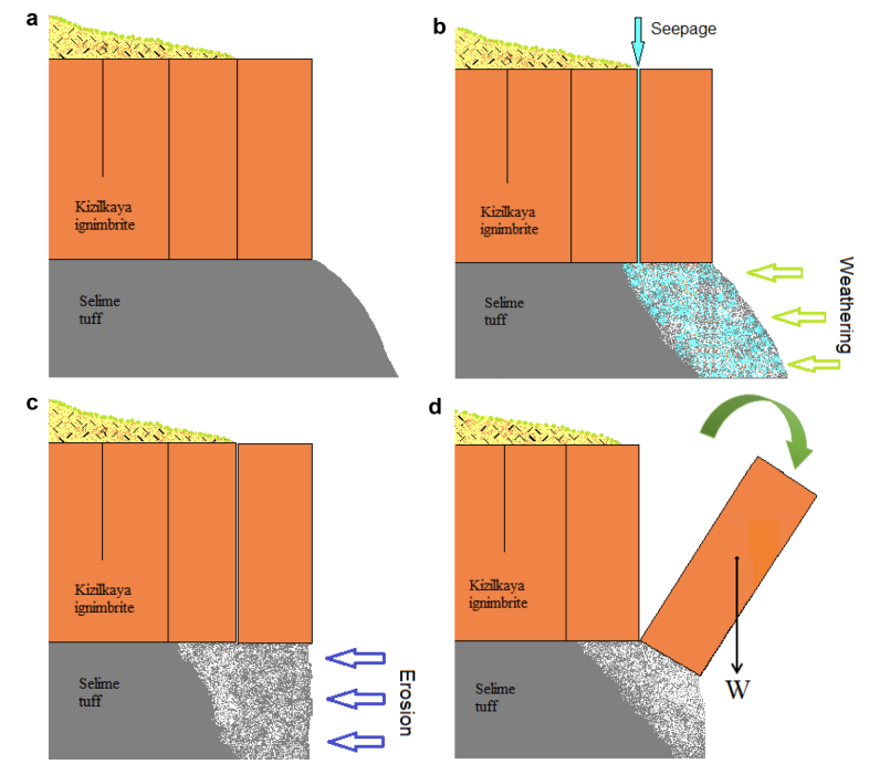
Beneath the ignimbrite lies the softer Selime tuff, an easily eroded layer that forms the valley's base (see Figure 1). The tuff's vulnerability to weathering and erosion significantly contributes to the instability of the ignimbrite cliffs above. This interplay between the hard ignimbrite and the soft tuff causes the valley's unique yet unstable landscape.
The Research Methods
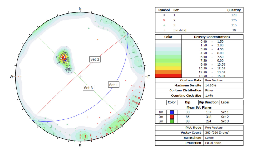
A combination of field investigations and numerical modeling were used in the research to analyze the secondary toppling failure mechanisms in the Ihlara Valley. Detailed geological mapping and discontinuity surveys were conducted to characterize the stratigraphy and structural features of the rock mass. Using a Brunton compass and measuring tape, measurements of joint orientations and spacings were recorded and processed with DIPS to identify the dominant joint sets influencing slope stability.
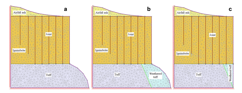
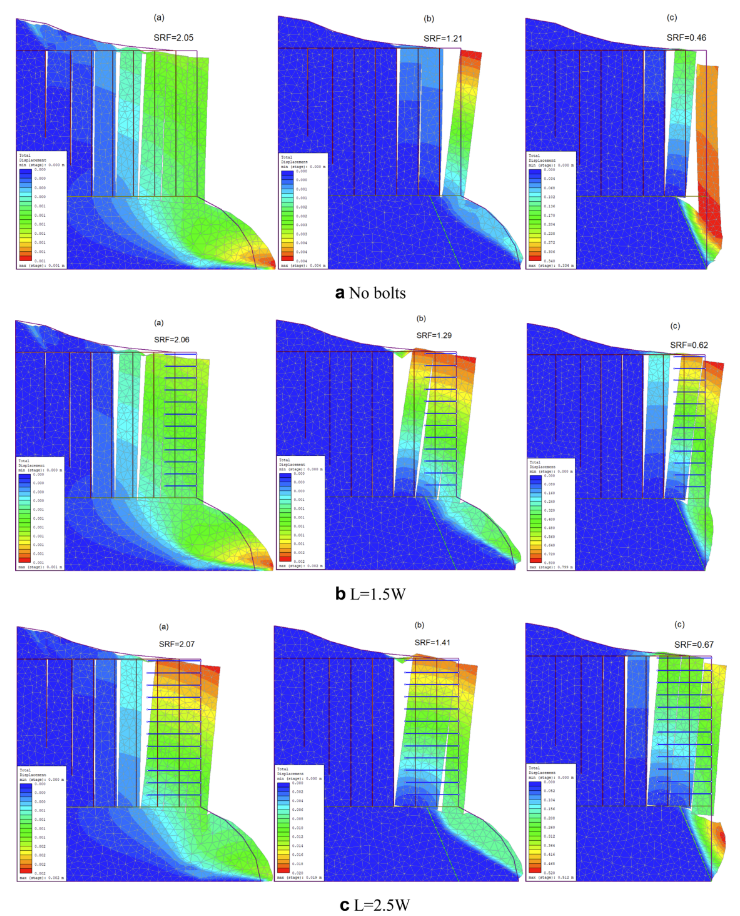
For the numerical analysis, three FEM models were constructed in RS2 to represent different stages of secondary toppling failure, which incorporated key assumptions like boundary conditions, gravitational stress properties, and joint representation. The shear strength reduction (SSR) technique was used to determine the stability of the slopes by progressively reducing the shear strength properties until failure occurred. Different block sizes were evaluated to assess the effect of the width-to-height (W/H) ratio on slope stability.
Based on the FEM analysis, fully bonded rock bolts were proposed as the optimal support system. Calculations determined that rock bolts should be at least 5.75 meters long and spaced in a 2.0 x 1.75-meter grid pattern to stabilize blocks effectively. Approximately 24 rock bolts were required for a block width of 3.5 meters. Researchers assessed the proposed rock bolt configurations by comparing the stress reduction factor (SRF) values before and after support installation, which revealed significant improvements in stability, especially in the later stages of failure.
The Research Conclusions
By examining three stages of secondary toppling failure, the research emphasized the need for tailored remedial measures based on the progression of instability. This Ihlara Valley research provided key insights into failure modes and rock bolt stabilization using RS2 software. Below are a few of the key findings.
Failure Modes Across Stages: The numerical models detected different modes of failure depending on the slope failure stages. Early stages were dominated by circular shear failure of the basal soft rock mass. As failure progressed, differential settlement and undercutting led to rotation or slumping of detached blocks in the overlying hard rock mass.
Rock Bolt Installation: For effective stabilization in the later stages of failure, rock bolts should have a length at least 2.5 times the width of the block being stabilized. The bolts should anchor at least two adjacent blocks of the overlaying rock mass together for adequate stability.
Bolt Arrangement Impact: The arrangement of the bolts, whether horizontal or inclined, did not significantly affect the increase in SRF or the reduction in block displacement. Both configurations only marginally improved stability, increasing SRF values slightly.
Immediate Treatment Required: The Ihlara Valley slopes may require immediate treatment with rock bolting to address the current instability issues. Given the various failure stages, quick intervention with properly designed rock bolting could prevent further deterioration.
Alternative Stabilization Techniques: While immediate rock bolting may be necessary, improving the mechanical properties of basal soft tuff, sealing vertical joints with grout to increase shear strength, and creating diverting channels at the slope crest to prevent water seepage could be cost-effective long-term solutions. These methods could complement rock bolting and reduce overall remediation costs.
What Other Environmental Challenges Can RS2 Solve?
RS2 is a versatile tool capable of addressing various geotechnical and environmental challenges:
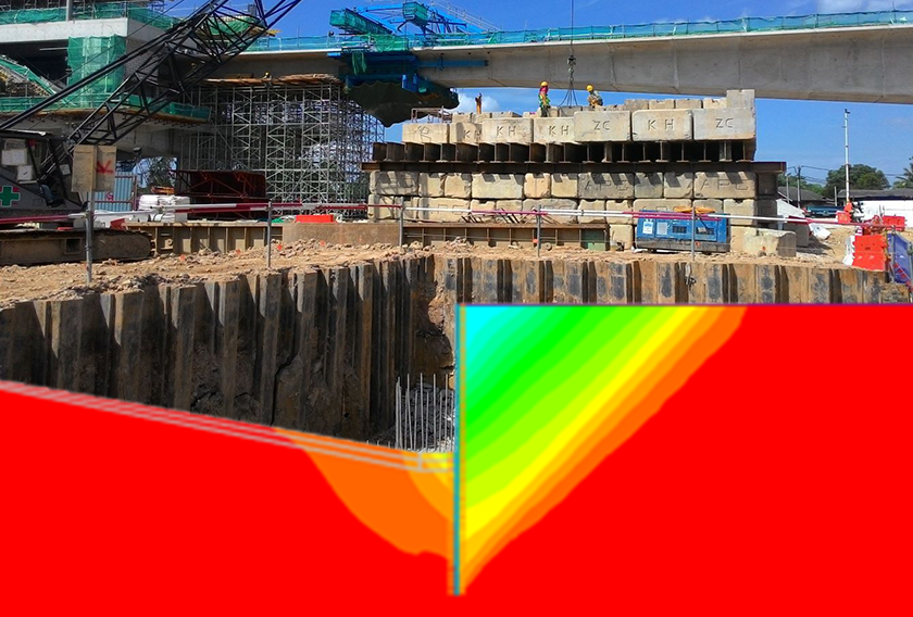
- Landslide Mitigation: Analyze slope stability under different conditions to design support systems that prevent landslides, protecting infrastructure and communities.
- Tunnel Design and Support: Model tunnel behavior during excavation to design appropriate support systems, ensuring stability and safety throughout the construction process.
- Groundwater Seepage Analysis: Assess the impact of groundwater on slopes to design effective drainage systems, preventing slope failures caused by water infiltration.
- Open Pit and Mine Stability: Evaluate the stability of open-pit mines, enabling safe and efficient resource extraction while minimizing environmental impacts.
Conclusion
The ignimbrite cliffs of the Ihlara Valley present significant toppling failure challenges, but this research showed the stages clearly and provided actionable strategies for stabilization using RS2 and DIPS. It pinpointed the key role of differential settlement and undercutting and advocated for precise rock bolt installations.
The beautiful yet crumbling ignimbrite formations in the Ihlara Valley serve as a stark reminder: without intervention, they’re at risk. This research enhances our understanding of ignimbrite stability and offers a blueprint for addressing similar geological hazards worldwide.