Can XFEM Solve the Meshing Challenges Posed by Complex Rock Slope Stability?
The finite element method (FEM) is the most common approach to modeling the behavior of rock masses, including ones intersected by discontinuities such as joints, faults, and cracks. That should come as no surprise since the method is well-understood by the industry and is known to work well even in moderately jointed domains where two-dimensional (2D) modeling is sufficient. Yet creating a robust finite element mesh for highly jointed rock masses remains a challenge, particularly when many closely spaced and intersecting joints are present and three-dimensional (3D) modeling is required. That’s where the extended finite element method (XFEM) comes in.
Approaches to mesh discretization: explicit joint vs. mesh independence
In the application of FEM to rock slope stability problems, discontinuities in a rock mass are explicitly modeled using interface elements to capture their behavior. While this approach works well with moderately jointed domains, it starts to fall apart when a large number of discontinuities with arbitrary orientation and spacing are present. That’s because the mesh must be aligned with the joints, making discretization a challenge or near impossibility.

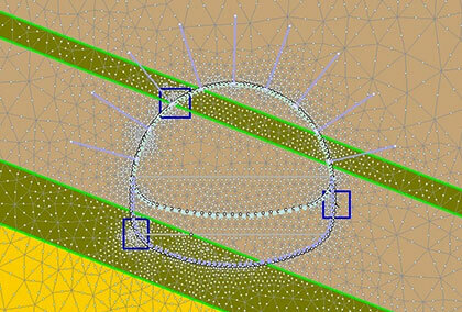
An alternative approach that seems more suitable for complex rock geometries is to first mesh the intact rock and then implicitly include the discontinuities in the formulation of the joints independently of the mesh (Figure 1). In this mesh-independent approach, known as the extended finite element method (XFEM), shear and normal discontinuity behavior is implicitly modeled by adding (enriching) additional degrees of freedom (DOFs) at each node of the mesh elements intersected by the discontinuities.
XFEM as a numerical framework for discretizing discontinuous domains
Although a recent study looks at the application of XFEM to 3D domains, it’s not until Rocscience’s research on XFEM, presented in a paper this year[1], that the method has been extended to the general case where an arbitrary number of joints can be represented in the rock mass.
Numerical integration over the intact rock is performed by standard Gauss points for 2D quadrilateral and triangular elements, and linear Gauss points are used for joint elements. In XFEM, discretization of the domain is independent of the joint’s position. However, enriched nodes are added to all elements intersected by discontinuities to account for the discontinuous joint behavior. Depending on the number of joints in the element, additional DOFs are applied to each node (see Figure 2).

In the XFEM approach, discontinuous shape functions are used to interpolate displacements in the domain. Consequently, standard FEM integration algorithms must be modified to calculate integration in the domain and along the discontinuity. According to the joint location, each element is divided into sub-regions among the joints. As a result, the integration is performed along the discontinuities and all subdomains in each element. Figure 3 shows the steps for finding subdomains for an element intersected by three sets of joints.
According to the type of element, each subdomain can be divided into sub-triangles for integration. Our calculations show that for linear elements (i.e., three- and four-noded elements), only one (1) Gauss point is adequate to satisfy convergence. However, for higher-order elements, three (3) Gauss points should be employed in each sub-triangle.[2]
Applying XFEM to rock slope stability analysis
In keeping with the philosophy of sound geotechnical modeling, Rocscience put its XFEM numerical framework to the test by applying FEM and XFEM to Shear Strength Reduction (SSR) analyses conducted on three (3) progressively more jointed rock slope stability problems with the goal of assessing the accuracy of results and computational cost of XFEM in comparison with the explicit joint method.
In all three scenarios, a rock slope was subjected to gravitational loading and shear strength reduction (SSR) analysis was applied to cohesion and the frictional angle to determine the factor of safety (FOS) and the strength reduction factor (SRF)[3] for each XFEM and FEM analysis. Total displacement and maximum shear strain at the point of failure (i.e., FOS) were calculated for each method to determine the accuracy of the XFEM results.
Problem 1. Parallel joints in close proximity
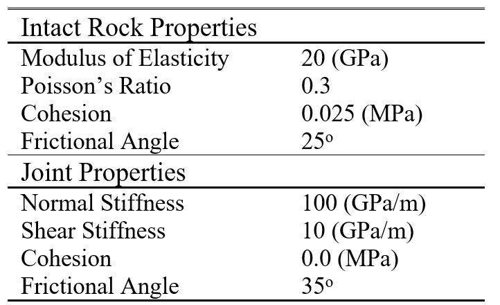
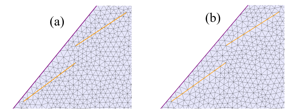
In the first problem, stability of slope was examined in a domain with three (3) pre-existing parallel joints in close proximity (see Table 1 for rock and joint properties). A comparison of mesh discretization between the two methods can be seen in Figure 4.
The simulation was performed in six (6) loading steps and the SRF was calculated as 1.37 for XFEM and 1.4 for FEM, showing close agreement between the two methods.
Total displacement at the point of failure in the XFEM analysis is shown in Figure 5 while a comparison of displacement between the two methods is plotted in Figure 6. The maximum shear strain in the domain at the point of failure for XFEM is presented in Figure 7.


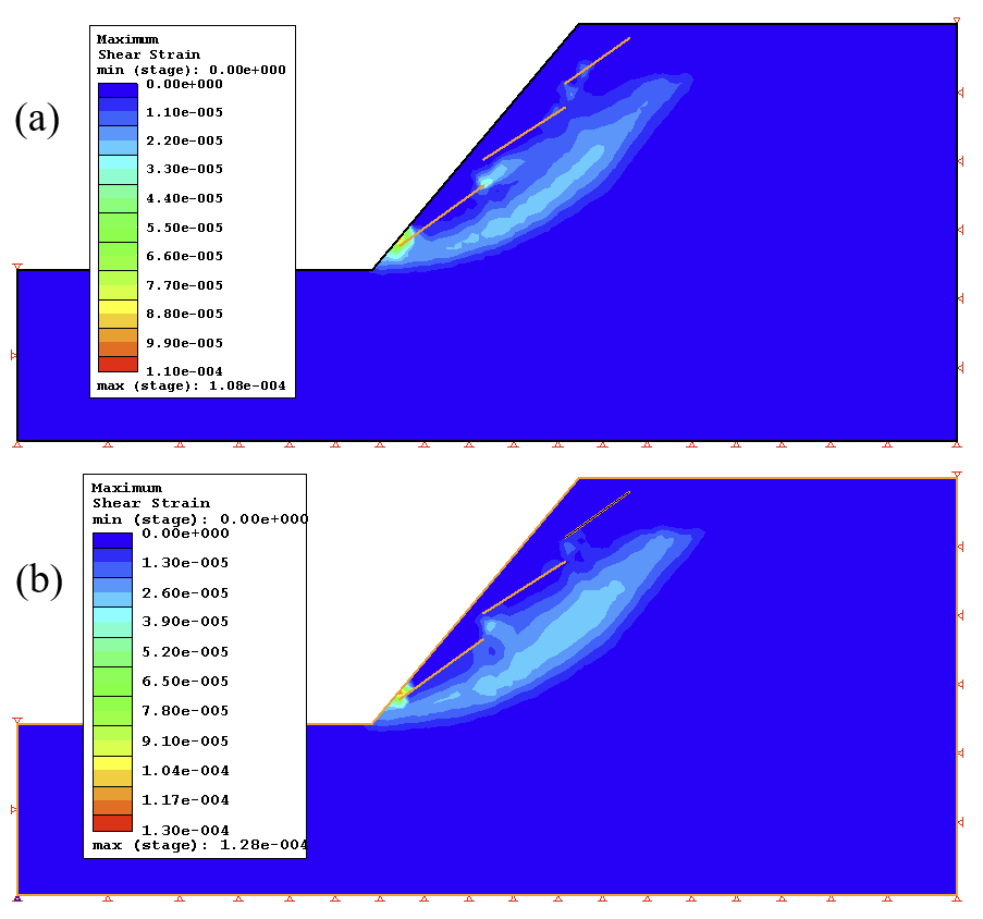
The very good agreement in total displacement and close agreement in maximum shear strain between the two methods are safe indicators of the accuracy of XFEM results.
Problem 2. Parallel joints with 10m spacing
In the second problem, stability of slope was examined in a rock mass with parallel joints spaced at 10 meters (see Table 2 for rock and joint properties).
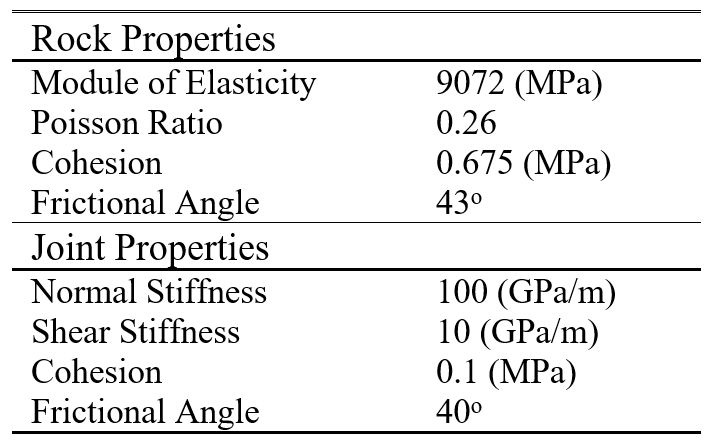
Gravitational load was applied in eight (8) steps and SRF for both methods was calculated as 1.4. Total displacement at the point of failure in the XFEM analysis is shown in Figure 8 while a comparison of displacement between the two methods is plotted in Figure 9.


As in Problem 1, there was a clear agreement in total displacement at the point of failure between the two methods, once again demonstrating the accuracy of XFEM results.
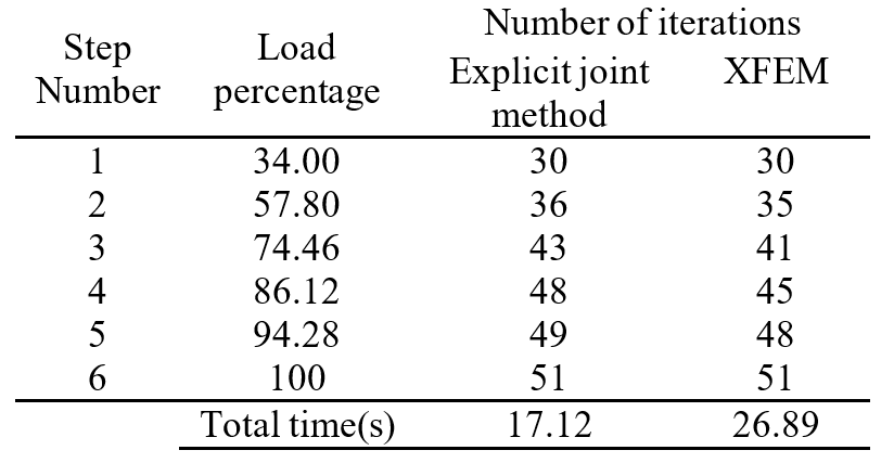
In this problem, computation time and number of iterations were considered and compared between FEM and XFEM. In Table 3, we show the resulting number of iterations required per loading step and the associated calculation time (in seconds) for each method. Evidently, less computational time is required for the explicit joint method compared to XFEM.
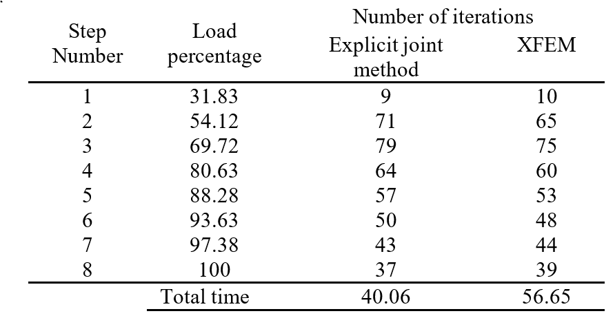
We also compared computational time for different types of elements (linear and higher order), as shown in Table 4. From these results it can be concluded that, for linear elements (three- and four-noded), the computational cost is similar. However, when using higher-order elements, more integration points are required in XFEM analysis, and thus computation time is increased.

Problem 3. Randomly distributed joints
In the third and final problem, slope stability was examined for numerous joints distributed randomly throughout the domain. And it’s in this problem that the ability of XFEM to meet the meshing challenges of complex geometries really comes through.
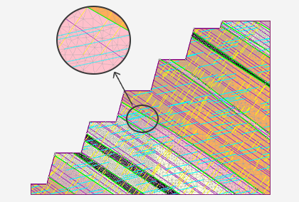
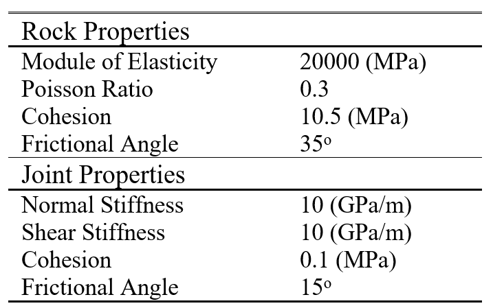
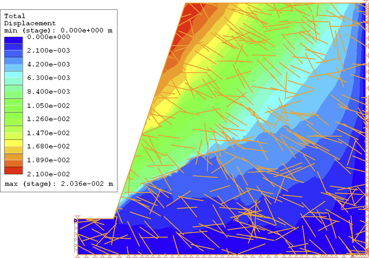
The geometry of the slope and position of the joints for the problem are depicted in Figure 10, consisting of a 70m x 80m slope with 452 joints randomly distributed in the domain. The material properties of the domain are shown in Table 5. Six-node elements were used in the mesh discretization.

Gravitational loading was implemented in six (6) steps, and the total number of DOFs, integration points, and elements were calculated, as shown in Table 6. Although more unknowns in the XFEM analysis meant more computational time, use of an optimization technique resulted in comparable computation times between the two methods (see Table 7).

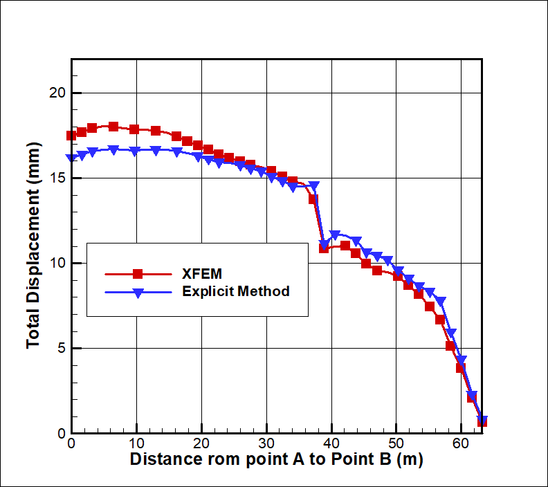
As in the first two problems, SRF was calculated for each method and again found to be in close agreement, and total deformation along the face slope was compared (see Figures 11 and 12). Results were also in very close agreement, confirming yet again the accuracy of results for the XFEM analysis.
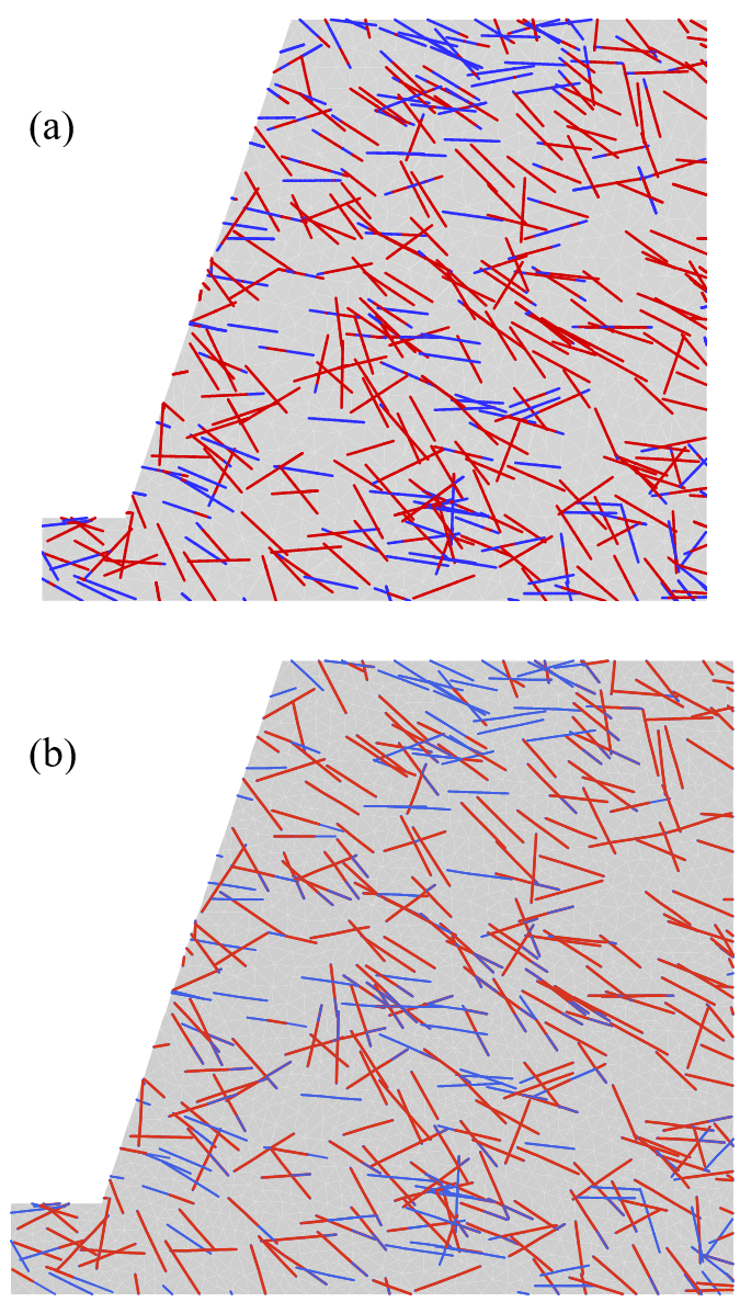
As further confirmation of the accuracy of XFEM results, we obtained the yielded joints in the domain for each method, as plotted in Figure 13. As shown, results for the two methods were consistent throughout the domain.
Conclusions and thoughts for the future
The one clear benefit of the extended finite element method (XFEM) that emerges from our analyses is its ability to create and discretize the mesh independently of the position of the joints in the domain. Even if the computational cost of XFEM is higher, it’s comparable enough to not outweigh the benefit of mesh independence. From this, it appears to us that XFEM is a suitable candidate for solving complex geometries, particularly in 3D domains where meshing can be a major challenge.
But perhaps the most important takeaway is our demonstration of the accuracy of XFEM analysis results, as evidenced by the very close agreement with FEM in the computation of SRF, total deformation, and maximum shear strain. This assurance opens the door to further exploration of XFEM as a sound and practical solution to the meshing challenges posed by complex rock slope stability.
References
[1] Sina Moallemi, John H. Curran and Thamer Yacoub. On Modeling Rock Slope Stability Using XFEM. Rocscience, Inc., 2018.
[2] A complete discussion of the governing equations for rock masses, discretization of space, and integration algorithms applied in the analyses can be found in Sections 2 and 3 of the paper.
[3] For a detailed description of SSR and SRF, see Section 2.2 of the paper.
