The Latest RS2 comes with new features for Groundwater and Seepage Analysis
Like with most technological advancements, innovation often breeds innovation, and such is the case with this latest addition to RS2’s Seepage Analysis functions. After a new feature was added to Slide2 and RS2 that allowed for users to define anisotropic strength parameters in their model, a flood of requests were made for adding a similar feature for anisotropic permeability during one’s seepage analysis. This new feature is one of many being added to the latest release of RS2.
Anisotropic Permeability: K1 Surface Option
As you know, when doing a seepage analysis in RS2, the soil permeability can either be defined as either isotropic or anisotropic. The permeability of the soil determines how the groundwater will drain and plays a critical part in performing a proper seepage analysis (as well as slope stability analysis). The pore water pressure distribution in your material affects directly affects the accuracy of the slope stability analysis and determined factor of safety.

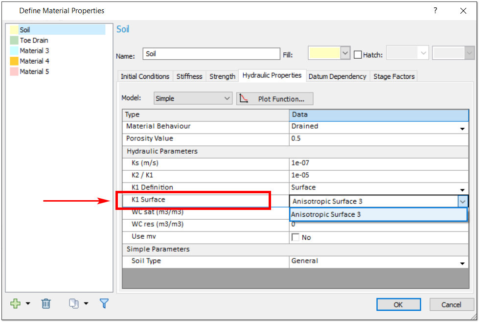
A new K1 Surface option was added that allows a user to assign the K1 line to an anisotropic surface. Previously users would enter a specific K1 angle. Now a drop-down option has been added to the Hydraulic Properties tab of the Define Materials dialog, which allows the user to select either the K1 Angle or K1 Surface option. If the user selects the K1 Surface option, they can select an anisotropic surface as the K1 line. Anisotropic surfaces can be added by selecting the Add Anisotropic Surface option in the Boundaries menu and applying it to your model with your mouse.
This quick and simple to use option can have a huge impact on the results of your analysis. As previously mentioned, getting a more accurate pore water pressure distribution means more accurate slope stability results and better-informed designs of slopes and supports. With this new option, users will have a much easier experience dealing with the real, practical problems of today, where materials are often not isotropic in their formation.
Other New Ground Water Features
In addition to this soil permeability feature, two other exciting groundwater features have been added to the program.
A new option has been added to the Groundwater tab of your Project Setting for restraining excess pore pressure. If the checkbox for the Restrain excess pore pressure from undrained material option is selected, the excess pore pressure generated from the undrained material in your model will also follow the boundary conditions of the Finite Element Groundwater.
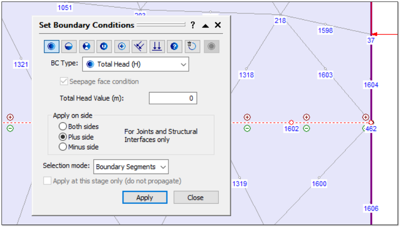
These mentioned Boundary Conditions now have additional functions as well. With joints, users can now select which side of a joint to apply the specific boundary conditions. This option becomes available when setting boundary conditions in a Steady State groundwater analysis. Specifically, if the Groundwater Method is selected as Steady State FEA or Transient FEA in Project Settings, then the groundwater (hydraulic) boundary conditions can be specified with the Set Boundary Conditions option in the Groundwater menu.

When a joint is selected, users are given the option to select a specific side of the joint indicated by a plus (+) or minus (-) symbol.

