The Wait is Over: This New RSPile Feature Makes Helical Pile Design More Efficient
- Ali Chaudhry, Geotechnical Project Manager at Rocscience
- Ahmed Mufty, Senior Geomechanics Specialist
Helical piles are ideal for projects with tight timelines because they’re faster to install with minimal soil disturbance. Now, you can model them accurately and efficiently in RSPile.
By introducing Helical Piles as an additional individual pile capacity calculation option, you can now define pile sections and pile types, similar to driven and bored piles, and specify helices along the shaft. With a wider range of piles available for engineers to model, RSPile is an even more versatile tool for comprehensive analysis and design.
What Are Helical Piles?
Helical piles, sometimes called “screw piles”, are foundational steel shafts with helices welded along their length. They are installed by connecting the pile lead to a torque motor and drilling the pile directly into the ground. This method is time-efficient and only minimally disrupts soil, which reduces the need for soil restoration. Post grouting may also be applied.
Creating Helical Piles in RSPile
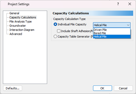
You can find helical pile capacity under the Individual Pile Capacity drop-down list in the Capacity Calculations tab of the Project Settings dialog, as shown in Fig.1.
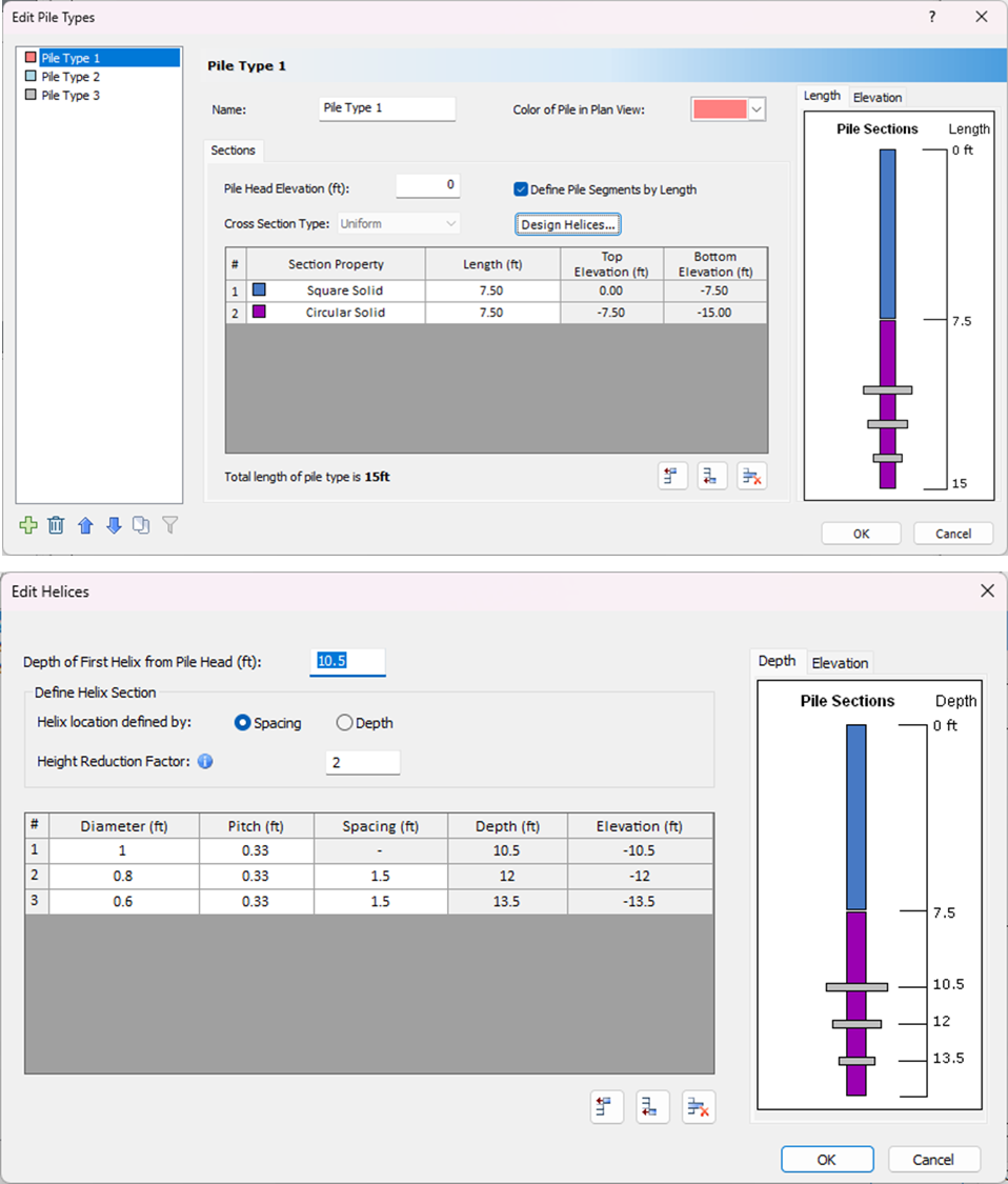
After defining the pile section properties using Define Pile Sections Properties window, you can specify the pile shaft lengths in the Pile Types dialog. Click the Design Helices button to define the diameter, pitch, spacing, or depth from pile head for each helix (Fig. 2).
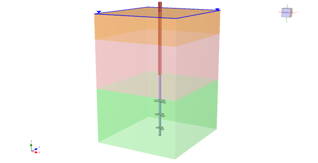
Once the helical pile has been defined, you can add it to the model and proceed with the computation. Figure 3 shows a helical pile embedded into a soil profile obtained from multiple boreholes with groundwater enabled.
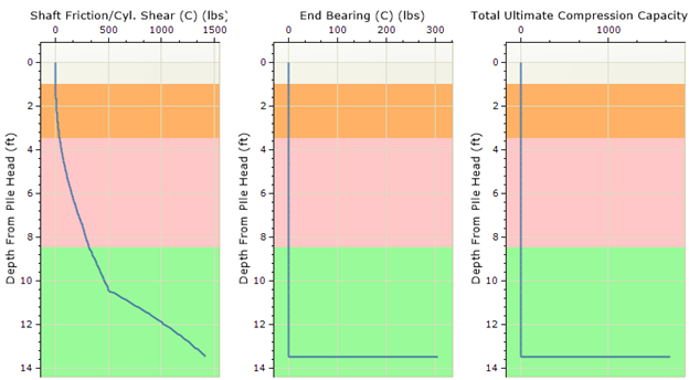
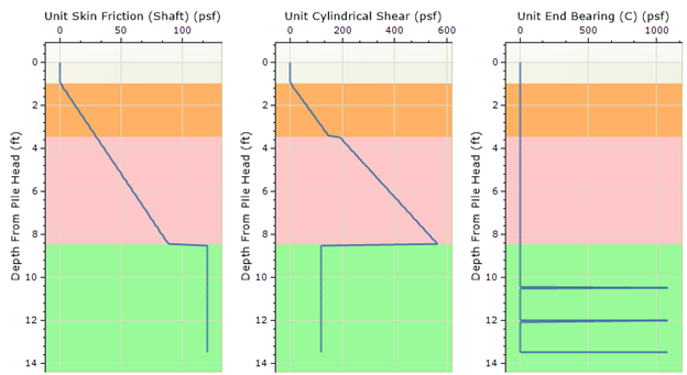
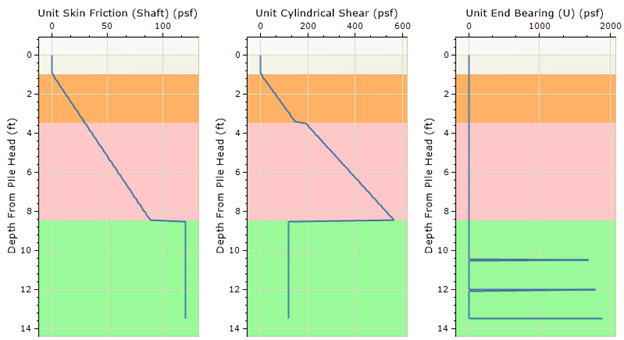
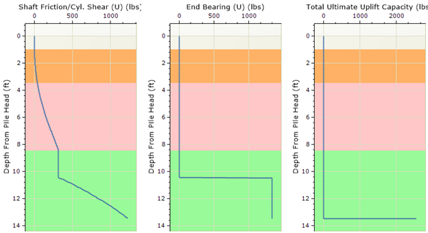
Detailed results can be viewed by selecting Results > Graph Pile. The results for compression and uplift are displayed in their respective tabs within the graphing interface. RSPile will produce the following results for both uplift and compression:
- Unit Skin Friction on the Shaft
- Unit Cylindrical Shear
- Unit End Bearing
- Total Shaft Friction/Cylindrical Shear
- Total End Bearing
- Total Ultimate Capacity
Examples of graphs for compression and uplift are shown in Figures 4 and 5, respectively. RSPile calculates all capacities using limit state analysis, choosing the minimum between helical plate bearing capacity and the combination of cylindrical shear capacity with optionally included shaft friction.
The Future of Pile Design is Here
With helical pile modelling, RSPile is now an even stronger tool for engineers who need versatile pile design solutions. When you’re working on a fast-paced project requiring minimal soil disturbance and precision when calculating compression and uplift capacities, RSPile ensures that your models are accurate and efficient.
Experience helical pile modelling in RSPile for yourself! Start your free trial today and see how you can elevate your next foundation project.