Wick Drain & Vacuum Consolidation in RS2
One of the new features in RS2 2019 is the ability to model wick drain installations when analyzing time-dependent soil consolidation with transient groundwater seepage analysis. The feature includes the optional use of vacuum consolidation, a soil improvement method often used in conjunction with wick drain installation.
About wick drains and vacuum consolidation
Wick drains are installed in soft soils to accelerate the rate of consolidation. The drains are typically made up of a plastic strip with drainage patterns wrapped in a geotextile filter that prevents soil particles from entering the channels and clogging the drain. Wick drains shorten the drainage path of pore water, allowing soil consolidation to occur in a matter of weeks rather than years.
The vacuum consolidation method is a construction improvement technique for consolidating and stabilizing soft clayey soil. It is often used in conjunction with wick drain installations and works by applying vacuum suction to a soil mass to reduce pore water pressure.
Modeling wick drains in RS2
Wick drain installation is a new option for modeling time-dependent soil consolidation with transient groundwater seepage analysis. Wick drains are added to a model using the new commands in the Groundwater menu.
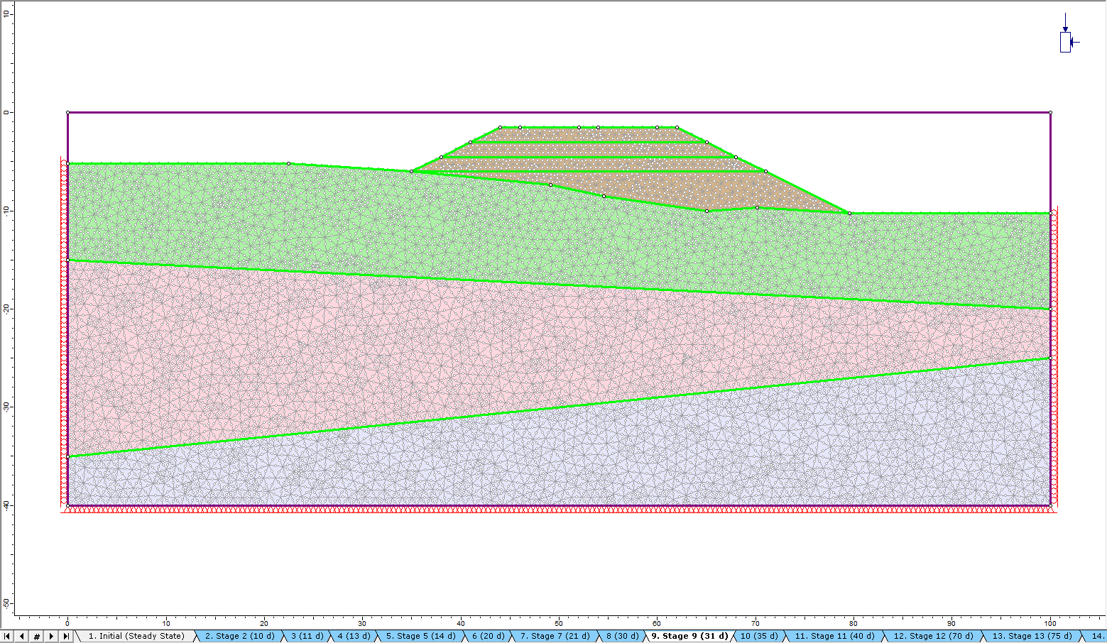
Figure 1 below shows the geometry of a staged embankment and consolidation model with completed project settings, setup of time-dependent stages, specification of material and hydraulic material properties, and setting of material and groundwater boundaries.
Adding a wick drain pattern
Wick drains are added to the model as a wick drain pattern using the Groundwater > Add Wick Drain Pattern command.
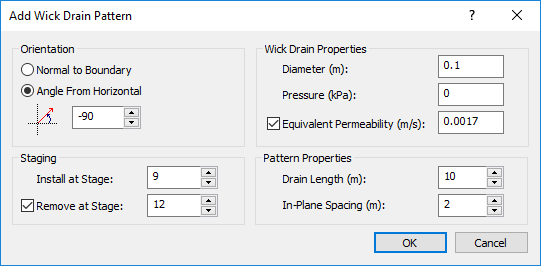
When adding a pattern, you can specify the stage at which the drains are added to the model and, optionally, the stage at which they are removed (Staging). Other specifications include Wick Drain and Pattern Properties such as drain diameter and length as well as the spacing between individual drains.
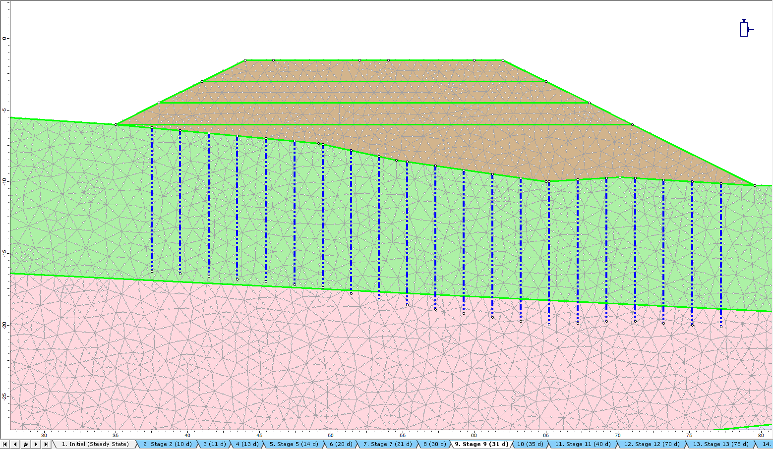
After specifying a pattern, you select the segment of the material boundary in the model along which to add the drains. You can also define the segment by entering XY coordinates. Figure 3 displays the embankment model geometry after the wick drains are added.
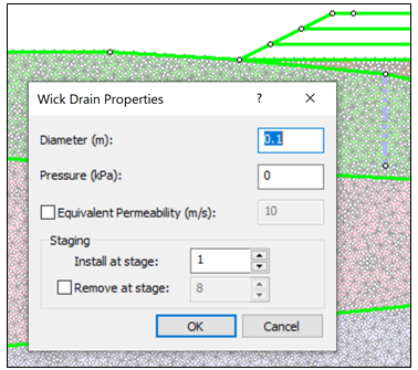
Other wick drain commands on the Groundwater menu allow you to edit and delete existing wick drains. In addition to adding wick drain patterns, you can add a single wick drain using the Groundwater > Add Wick Drain command, selecting the vertices on the model and entering drain properties as shown in Figure 3.
Adding vacuum consolidation
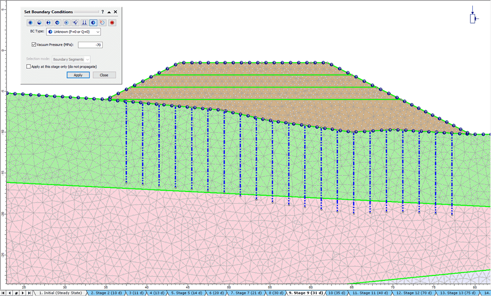
You add vacuum consolidation to the modeled wick drain installation by setting the P value for the Unknown Boundary Condition in the groundwater boundary conditions. Select the Groundwater workflow tab and then select Groundwater > Set Boundary Conditions. Select Unknown in the dropdown list, check the box for Vacuum Pressure, and set the value to -70, as shown in Figure 5.
Visualizing vertical displacement
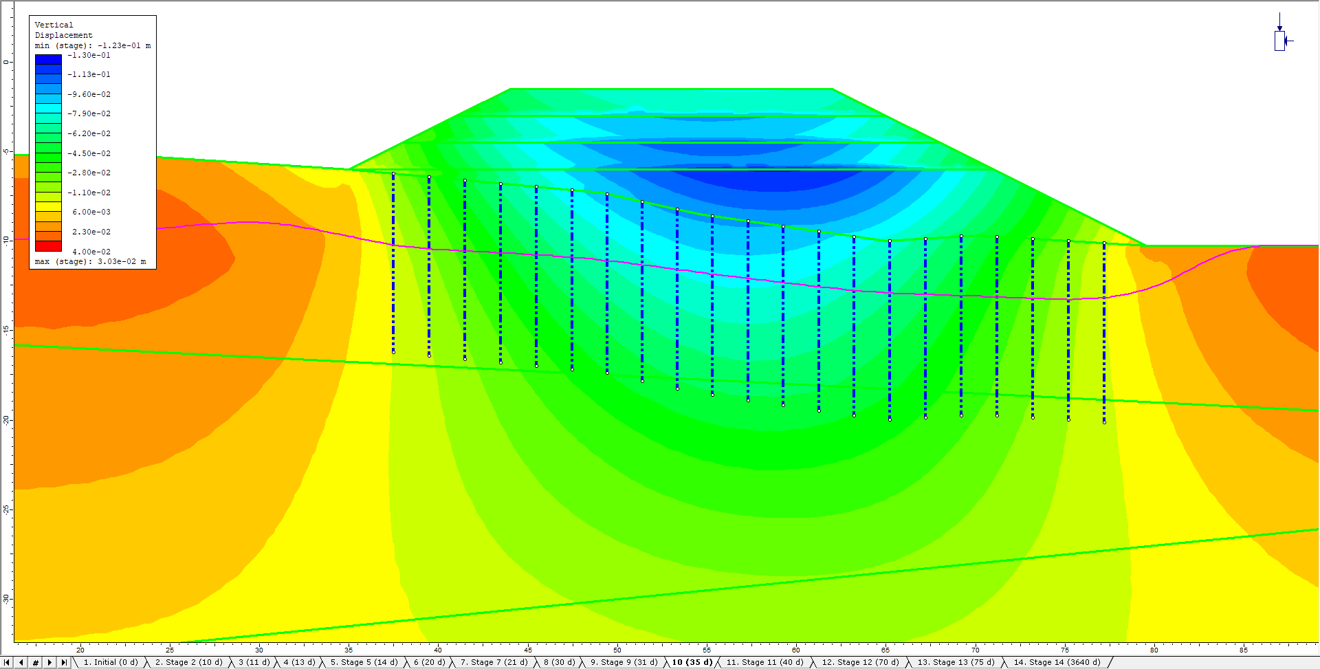
The following RS2 visualizations of vertical displacement in the modeled embankment demonstrate the impact of implementing wick drains and vacuum on the rate of consolidation in soil embankment applications. For comparison purposes, vertical displacement is calculated for each of three scenarios: 1) without wick installation, 2) with wick installation, and 3) with wick installation and vacuum consolidation.
Figure 6 below provides a contoured visualization of the embankment’s vertical displacement in the third scenario: with wick drain installation and vacuum consolidation.
For comparison purposes, Figure 7 below provides a countered visualization of vertical displacement for each of the three scenarios: 1) without wick installation, 2) with wick installation, and 3) with wick installation and vacuum consolidation.
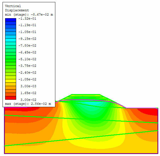
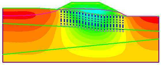
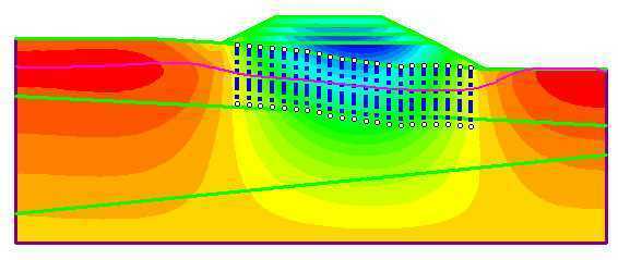
Figure 8 makes the comparison more evident by displaying plots of vertical displacement against time for each of the scenarios. The plots were generated in RS2 using a material query line.
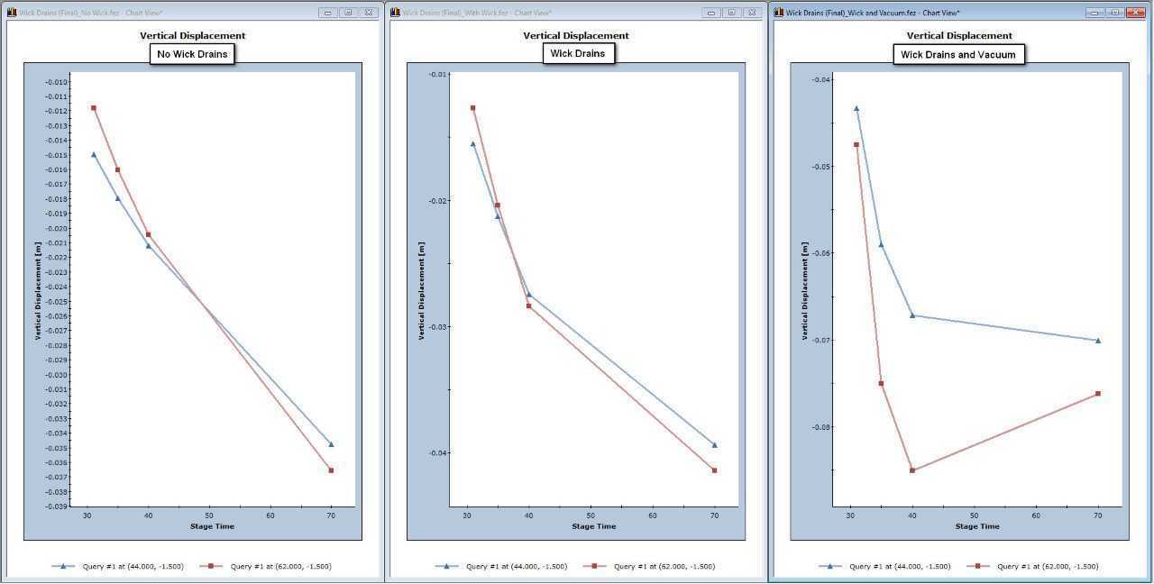
It is clear from the vertical displacement visualizations and plots presented above that the presence of wick drains in soil embankments increases the rate of consolidation. The speed of consolidation is further increased with the addition of vacuum consolidation.
For complete, step-by-step instructions for modeling the addition of a wick drainage system with vacuum to a typical road embankment application, see the RS2 Wick Drains tutorial.
