Grid Search
A Grid Search is one of the Search Methods available in Slide2 for locating the Global Minimum safety factor for CIRCULAR slip surfaces. In order to perform a Grid Search, the Surface Options dialog must be configured as follows:
- Surface Type = Circular
- Search Method = Grid Search
Slip Center Grid
A Grid Search requires at least one slip center grid to be defined. This can be done with either the Auto Grid or Add Grid options. See the Auto Grid and Add Grid topics for details about creating slip center grids. A typical slip center grid is shown below.
Example of slip center grid

More than one slip center grid can be defined if necessary, but in most cases, a single grid will be sufficient to analyze a problem.
How Does the Grid Search Work?
When a slip center grid is created, the number of grid intervals in the X and Y directions is specified. This creates a regular (rectangular or square) grid of slip centers.
Each center in a slip center grid, represents the center of rotation of a series of slip circles. By default, Slide2 uses the Slope Limits and the Radius Increment, to generate the circle radii at each grid point, as follows:
- First of all, the Slope Limits determine the "slope surface". The slope surface is simply the segments of the External Boundary between the Slope Limits. See the Slope Limits topic for more information.
- For each slip center in a grid, suitable Minimum and Maximum radii are determined, based on the distances from the slip center to the slope surface (see diagram below).
- The Radius Increment entered in the Surface Options dialog, is then used to determine a number of equally spaced circles, between the Minimum and Maximum radii, for a given slip center. This is illustrated in the figure below.
- Steps 2 and 3 are repeated for all slip centers in all grids, to generate all of the slip circles in a Grid Search.
Implementation of Grid Search

- The Radius Increment is actually the number of INTERVALS between the minimum and maximum radii circles at each grid point. Therefore the number of circles generated at each slip center grid point, is equal to Radius Increment + 1.
- The total number of circles generated for each grid, is therefore (# of grid intervals in X direction + 1) * (# of grid intervals in Y direction + 1) * (Radius Increment + 1). For the default values of grid spacing and Radius Increment, this results in 21 x 21 x 11 = 4851 slip circles per grid.
- After a grid is created, it can be deleted, moved, stretched (re-sized), or the number of grid intervals can be modified, using the options in the Edit sub-menu of the Surfaces menu.
Narrowing the Grid Search
Using the default Slope Limits to generate a Grid Search will give the maximum coverage for the search. If you wish to narrow the Grid Search to more specific areas of the model, two possibilities are available:
- You can customize the Slope Limits. By narrowing the Slope Limits, you will narrow the areas where slip surfaces will be generated. See the Define Limits and Move Limits topics for details about customizing the Slope Limits.
- You can create a Focus object, which will then be used instead of the slope surface, for determining the slip circle radii generated at each grid point. See the Focus Search topic for details.
Composite Surfaces
Normally, when circular surfaces are analyzed in Slide2, if a circular surface extends past the lower limits of the External Boundary, the surface is discarded and is not analyzed. A Grid Search may generate a large number of such surfaces, depending on your External Boundary geometry, and search parameters (grid location etc).
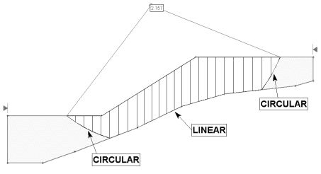
If the Composite Surfaces checkbox is selected in the Surface Options dialog, then circular surfaces which extend past the lower limits of the External Boundary will automatically conform to the shape of the External Boundary, between the two circle intersection points along the lower edge of the boundary. This is illustrated in the following figure.
Example of Composite slip surface.

Composite surfaces allow you to model a bedrock surface, for example, by entering appropriate coordinates for the lower edge of the External Boundary. You can then perform a circular surface search which will conform to the shape of the bedrock, by simply using the Composite Surfaces option. These surfaces will be analyzed and NOT discarded.
Reverse Curvature Surfaces
A "reverse curvature" surface in Slide2, refers to circular slip surfaces with a slip center below the maximum y-coordinate of the ground surface, such that part of the slip surface is above its own slip center, and therefore reverses direction. Obviously, such surfaces cannot actually exist, however, they may be generated by a Grid Search, if part of a slip surface grid extends below the maximum y-coordinate of the ground surface. If such surfaces are generated, the user has the option of handling them in two different ways, using the Create tension crack for reverse curvature option in the Surface Options dialog:
- If the checkbox is selected for the Create tension crack for reverse curvature option (which it is by default), then Slide2 will automatically generate a vertical tension crack where the slip surface begins to reverse direction (i.e. when the slip surface y-coordinate is equal to the slip center y-coordinate)
- If the checkbox is NOT selected, then such surfaces will simply be discarded from the analysis.
Surface Filter
See the Surface Options topic for details about the Minimum Elevation, Minimum Depth, Minimum Area, Minimum Weight slip surface filter options.