27 - Damage Regions (Generalized Hoek-Brown)
1.0 Introduction
This tutorial will cover how to define a damage region for a Generalized Hoek-Brown material.
In deep slope excavations, the rock near the surface of the excavation will be subject to reduced material properties from blast damage and stress relaxation. For Generalized Hoek-Brown materials, the parameter D is a "disturbance factor" which depends upon the degree of disturbance to which the rock mass has been damaged. It varies from 0 for undisturbed in situ rock masses to 1 for very disturbed rock masses.
Finished Product
The finished product of this tutorial can be found in the Tutorial 27 Damage Regions (final).slmd data file. All tutorial files installed with Slide2 can be accessed by selecting File > Recent Folders > Tutorials Folder from the Slide2 main menu.
2.0 Define Damage Region
There are various methods in the literature that can be used to determine the extent of the damage region.
For this example, we will assume the damage region extends perpendicular to the slope to a distance up to 0.3 times the height of the slope at the base of the slope, as shown in the image below.
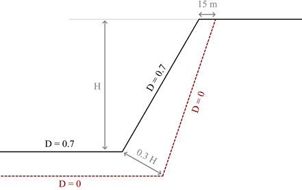
At the top of the slope, a horizontal distance of 15 m is defined for the extent of the damage region.
- Select File > Recent > Tutorials folder from the Slide2 main menu. Open the file titled Tutorial 27 Damage Regions - starting file.slmd.
- Go to Boundaries > Add Damage Region (D = 0).
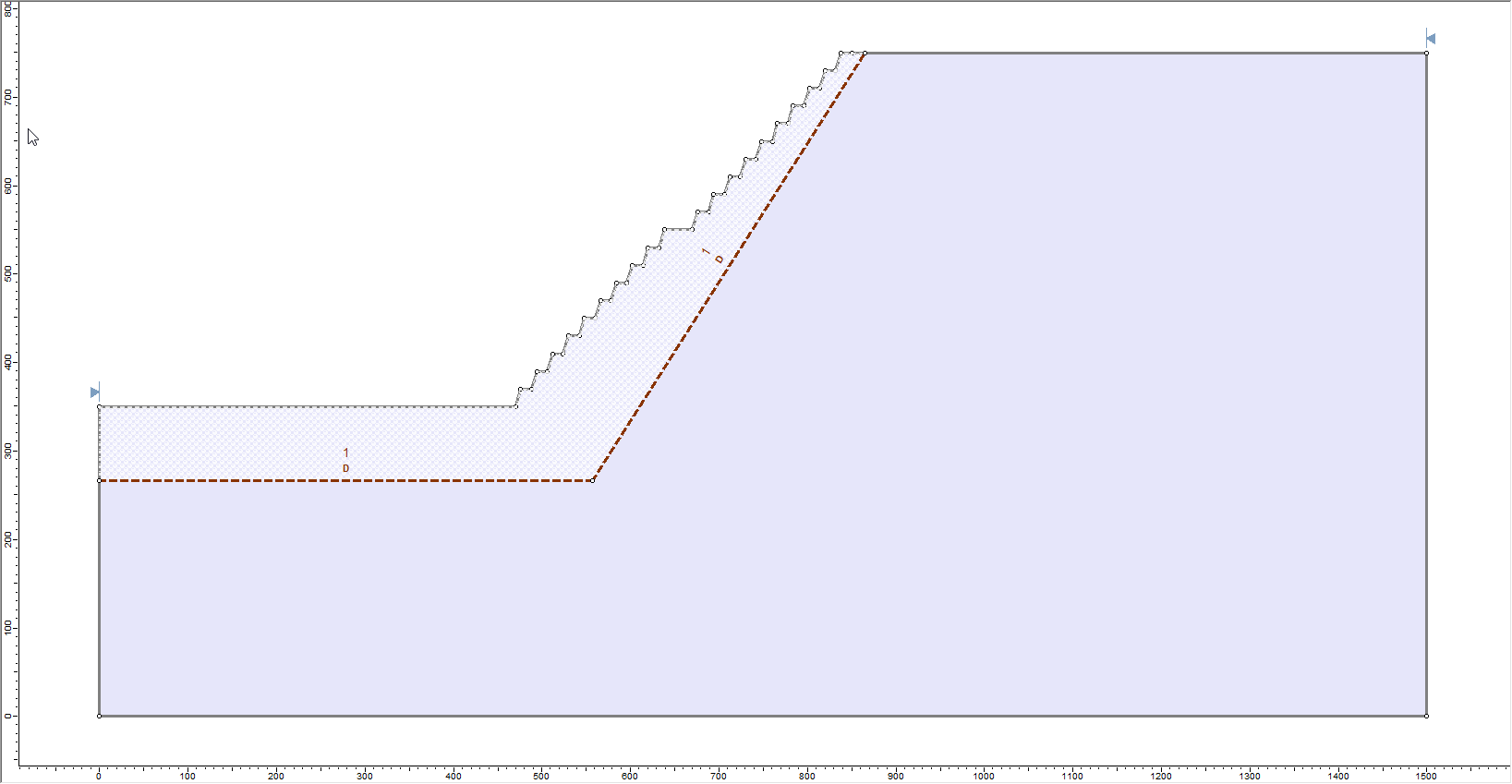
- Draw the polyline using the points: (0,267), (557,267), and (865,750). Press Enter to finish.
The D symbol should be shown above the polyline, and the materials above the polyline should have a hatch overlay:
3.0 Define Material Properties
Now, the properties of the surrounding rock mass need to be defined.
- Go to Properties > Define Materials

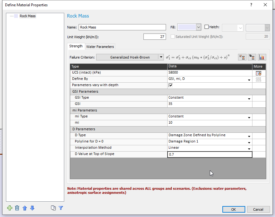
- Ensure UCS = 58,000 kPa is entered for the rock mass.
- Ensure Define strength using: GSI, mi, D is selected.
- Toggle ON the Parameters vary with depth checkbox, and click Define…
- Change the settings as follows:
- GSI Parameter: Constant, 35
- mi Parameter: Constant, 10
- D Type: Damage Zone Defined by Polyline
- Polyline for D=0: Damage Region 1 (this assigns the polyline that we just created to the material)
- Interpolation Method: Linear, with a value of 0.7 at the top of the slope.
- Click OK twice to return to the model.
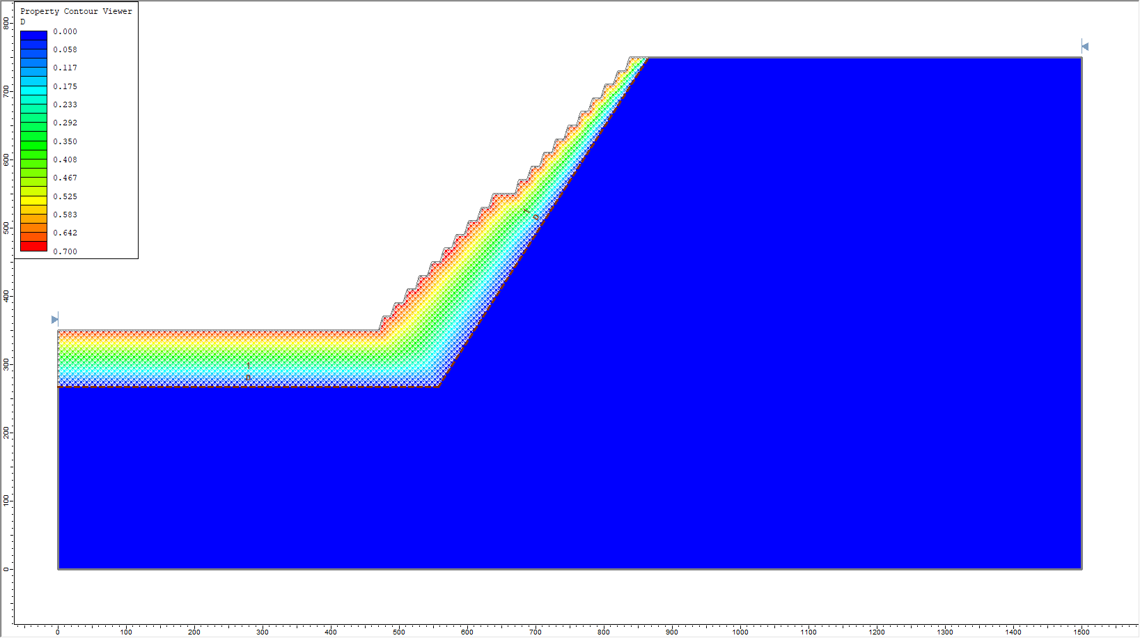
- Click Analysis > Property Viewer
 to view the variation of D within the material.
 - Save
 the model in a different location.
 - Compute
 the model. This may take a few minutes.
If a non-linear variation of the D parameter is preferred between the top of the slope and the polyline, you may also select the Piecewise option, and enter a table of values to define the change of D as a function of relative distance from the top of the slope (distance = 0%) and the polyline (distance = 100%). For detailed information on how the Piecewise or other D Type options work, please see the documentation on Generalized Hoek Brown.
4.0 Results
- Click on Interpret
 to view the computed results.
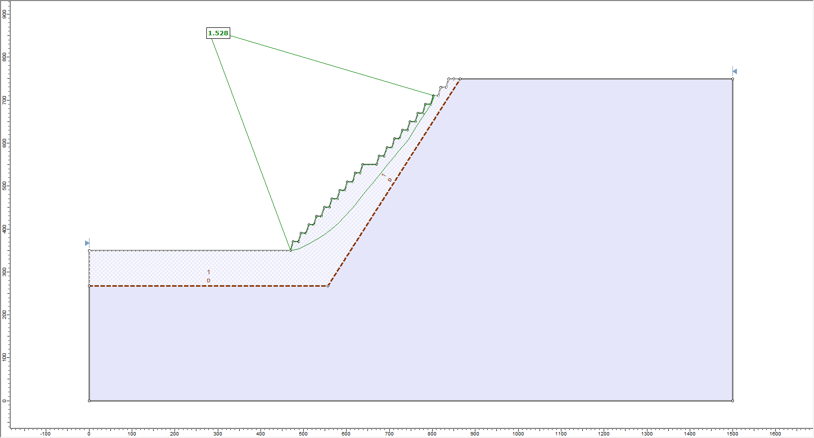
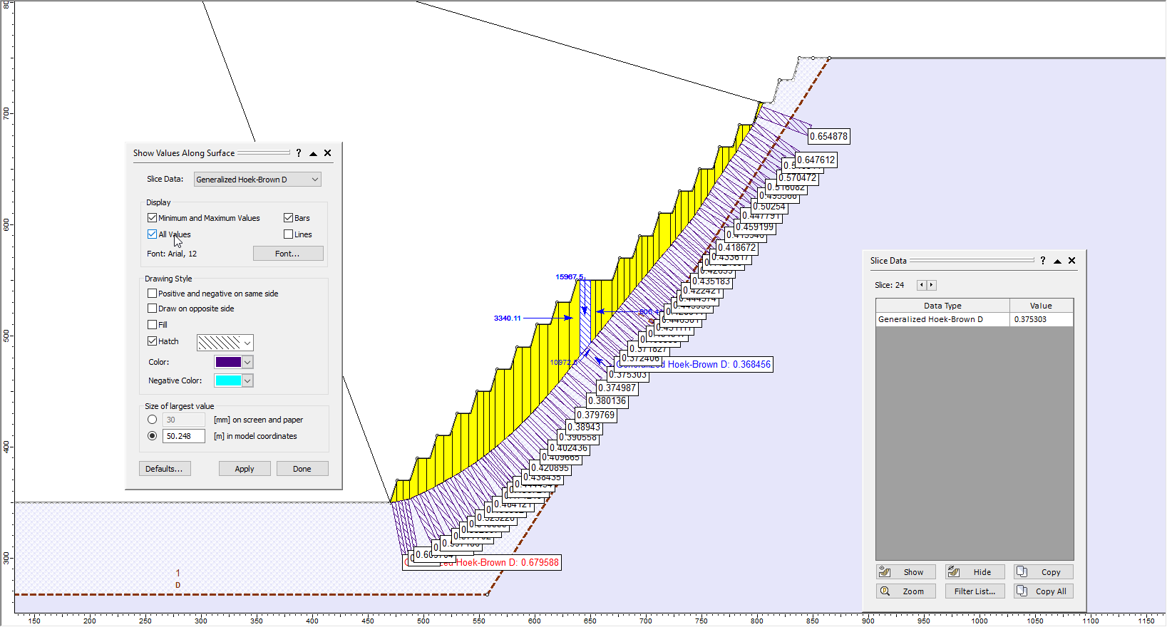
You can also view the actual values of D assigned to each slice during the computation via either of the following two options:
 Query Slice Data and click on a slice.
 Show Values Along Surface and select Slice Data: Generalized Hoek-Brown D. Toggle All Values.
This concludes the tutorial for damage region.